1994 JEEP CHEROKEE horn
[x] Cancel search: hornPage 274 of 1784
ELECTRICAL
GROUP INDEX
Group Group
AUDIO SYSTEMS....................... 8F
BATTERY/STARTER/GENERATOR SERVICE . . 8B
BATTERY/STARTING/CHARGING SYSTEMS
DIAGNOSTICS........................ 8A
CHIME/WARNING BUZZER SYSTEM....... 8U
HORNS............................... 8G
IGNITION SYSTEMS.................... 8D
INSTRUMENT PANEL AND GAUGES........ 8E
LAMPS............................... 8L
OVERHEAD CONSOLE................... 8CPOWER LOCKS........................ 8P
POWER MIRRORS...................... 8T
POWER SEAT.......................... 8R
POWER WINDOWS..................... 8S
REAR WINDOW DEFOGGER.............. 8N
TURN SIGNALS AND HAZARD WARNING
FLASHERS........................... 8J
VEHICLE SPEED CONTROL SYSTEM....... 8H
WINDSHIELD WIPERS AND WASHERS..... 8K
WIRING DIAGRAMS.................... 8W
BATTERY/STARTING/CHARGING SYSTEMS DIAGNOSTICS
CONTENTS
page page
BATTERY TEST PROCEDURES............. 2
ENGINE STARTER MOTOR TEST
PROCEDURES ON VEHICLE.............. 9GENERATOR TEST PROCEDURES ON
VEHICLE............................. 14
IGNITION OFF DRAW (IOD) DIAGNOSIS...... 8
USING ON-BOARD DIAGNOSTIC SYSTEM.... 19
GENERAL INFORMATION
The battery, starting, and charging systems oper-
ate with one another, and therefore, must be thor-
oughly tested as a complete system. In order for the
vehicle to start and charge properly, it must have a
battery that will perform to specifications. The
starter motor, generator, wiring, and electronics also
must perform within specifications. Group 8A covers
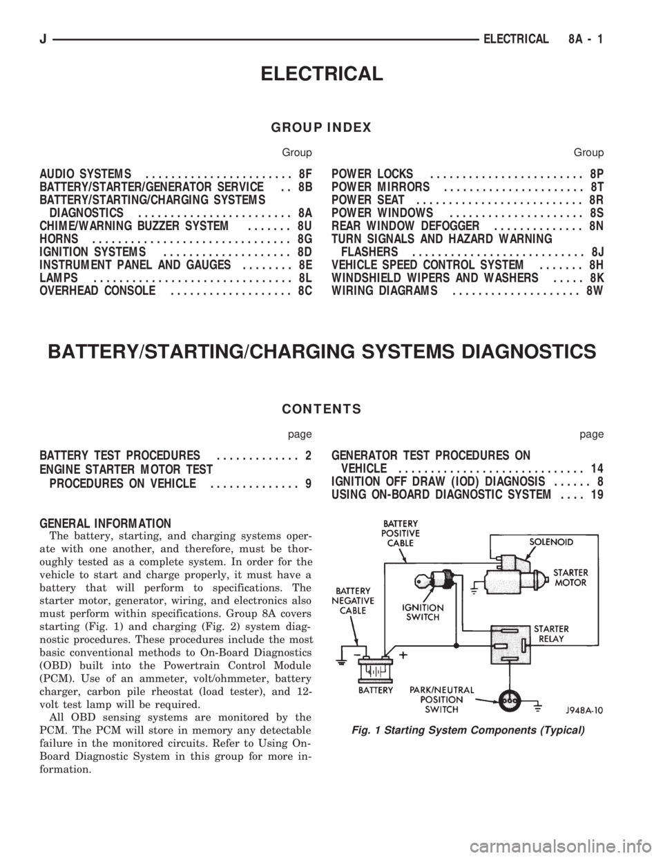
starting (Fig. 1) and charging (Fig. 2) system diag-
nostic procedures. These procedures include the most
basic conventional methods to On-Board Diagnostics
(OBD) built into the Powertrain Control Module
(PCM). Use of an ammeter, volt/ohmmeter, battery
charger, carbon pile rheostat (load tester), and 12-
volt test lamp will be required.
All OBD sensing systems are monitored by the
PCM. The PCM will store in memory any detectable
failure in the monitored circuits. Refer to Using On-
Board Diagnostic System in this group for more in-
formation.
Fig. 1 Starting System Components (Typical)
JELECTRICAL 8A - 1
Page 386 of 1784
HORNS
CONTENTS
page page
GENERAL INFORMATION.................. 1
HORN SWITCH (HORN PAD) REPLACEMENT . . 3
TORQUE SPECIFICATIONS................. 3XJ ..................................... 1
YJ ..................................... 2
GENERAL INFORMATION
For XJ/YJ vehicles battery voltage is applied to the
horn relay through a fuse.
When the horn switch is depressed, the horn relay
is grounded, pulling the contact closed and providing
battery voltage to the horns.
A slip ring and brush arrangement in the steering
wheel allows the switch circuit to maintain contact
while allowing rotation of the steering wheel.On XJ models, a cadmium-plated ground
screw is used to attach the horn(s) to the body.
Do not substitute other types of ground screws
as they may become corroded and cause a loss
of ground.
XJ
REPLACEMENT
(1) Raise and support the vehicle.
(2) Remove the splash shield.
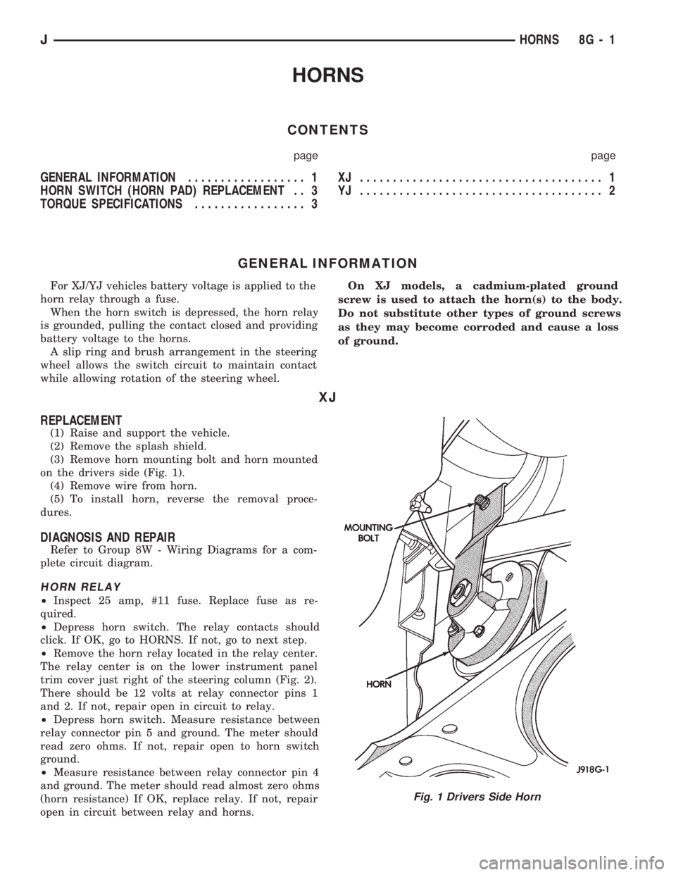
(3) Remove horn mounting bolt and horn mounted
on the drivers side (Fig. 1).
(4) Remove wire from horn.
(5) To install horn, reverse the removal proce-
dures.
DIAGNOSIS AND REPAIR
Refer to Group 8W - Wiring Diagrams for a com-
plete circuit diagram.
HORN RELAY
²Inspect 25 amp, #11 fuse. Replace fuse as re-
quired.
²Depress horn switch. The relay contacts should
click. If OK, go to HORNS. If not, go to next step.
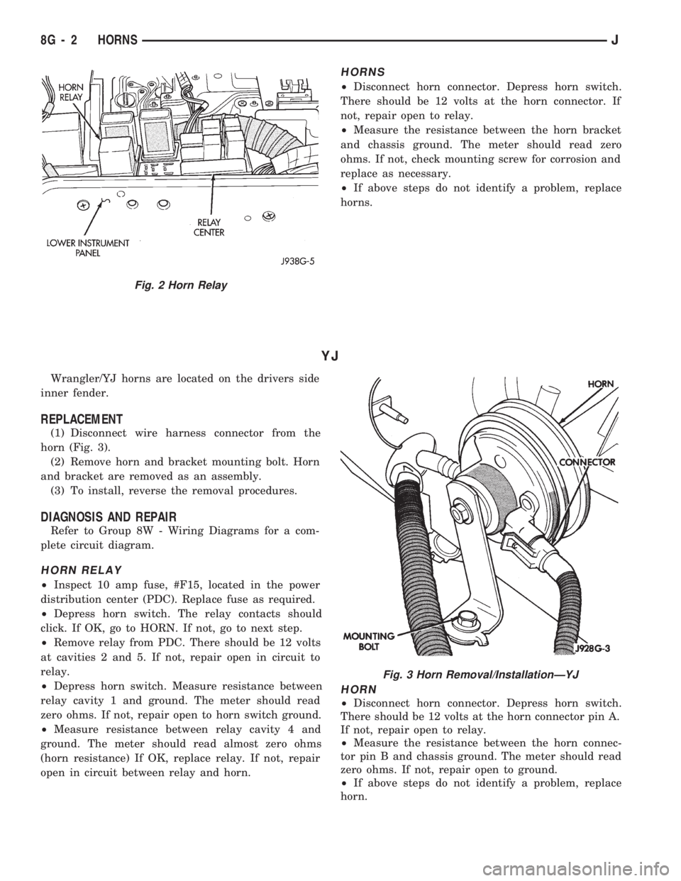
²Remove the horn relay located in the relay center.
The relay center is on the lower instrument panel
trim cover just right of the steering column (Fig. 2).
There should be 12 volts at relay connector pins 1
and 2. If not, repair open in circuit to relay.
²Depress horn switch. Measure resistance between
relay connector pin 5 and ground. The meter should
read zero ohms. If not, repair open to horn switch
ground.
²Measure resistance between relay connector pin 4
and ground. The meter should read almost zero ohms
(horn resistance) If OK, replace relay. If not, repair
open in circuit between relay and horns.
Fig. 1 Drivers Side Horn
JHORNS 8G - 1
Page 387 of 1784
HORNS
²Disconnect horn connector. Depress horn switch.
There should be 12 volts at the horn connector. If
not, repair open to relay.
²Measure the resistance between the horn bracket
and chassis ground. The meter should read zero
ohms. If not, check mounting screw for corrosion and
replace as necessary.
²If above steps do not identify a problem, replace
horns.
YJ
Wrangler/YJ horns are located on the drivers side
inner fender.
REPLACEMENT
(1) Disconnect wire harness connector from the
horn (Fig. 3).
(2) Remove horn and bracket mounting bolt. Horn
and bracket are removed as an assembly.
(3) To install, reverse the removal procedures.
DIAGNOSIS AND REPAIR
Refer to Group 8W - Wiring Diagrams for a com-
plete circuit diagram.
HORN RELAY
²Inspect 10 amp fuse, #F15, located in the power
distribution center (PDC). Replace fuse as required.
²Depress horn switch. The relay contacts should
click. If OK, go to HORN. If not, go to next step.
²Remove relay from PDC. There should be 12 volts
at cavities 2 and 5. If not, repair open in circuit to
relay.
²Depress horn switch. Measure resistance between
relay cavity 1 and ground. The meter should read
zero ohms. If not, repair open to horn switch ground.
²Measure resistance between relay cavity 4 and
ground. The meter should read almost zero ohms
(horn resistance) If OK, replace relay. If not, repair
open in circuit between relay and horn.
HORN
²Disconnect horn connector. Depress horn switch.
There should be 12 volts at the horn connector pin A.
If not, repair open to relay.
²Measure the resistance between the horn connec-
tor pin B and chassis ground. The meter should read
zero ohms. If not, repair open to ground.
²If above steps do not identify a problem, replace
horn.
Fig. 2 Horn Relay
Fig. 3 Horn Removal/InstallationÐYJ
8G - 2 HORNSJ
Page 388 of 1784
HORN SWITCH (HORN PAD) REPLACEMENT
(1) Disconnect negative cable from battery.
(2) Remove horn button by pulling straight up.
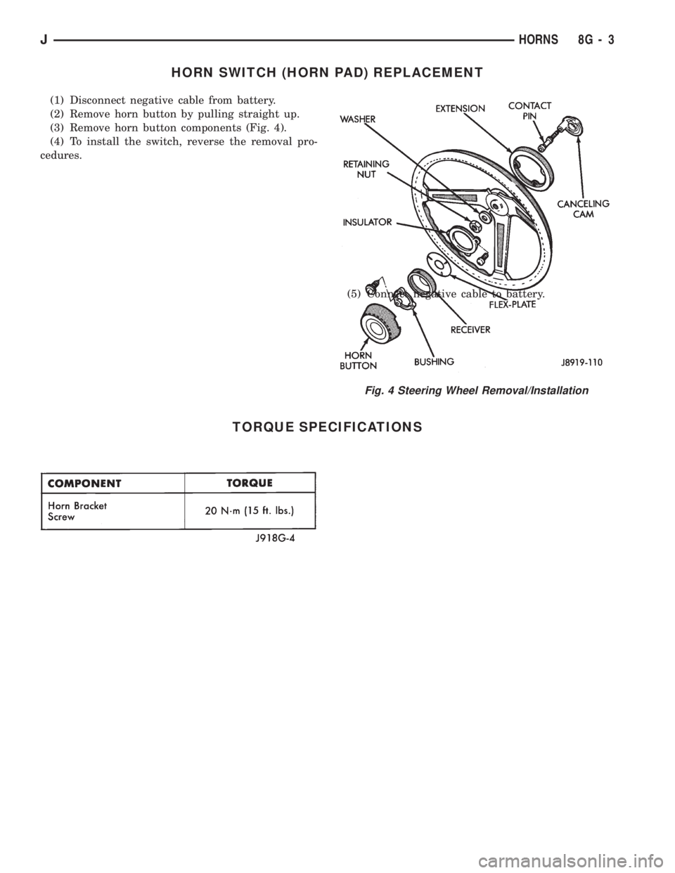
(3) Remove horn button components (Fig. 4).
(4) To install the switch, reverse the removal pro-
cedures.
(5) Connect negative cable to battery.
TORQUE SPECIFICATIONS
Fig. 4 Steering Wheel Removal/Installation
JHORNS 8G - 3
Page 398 of 1784
SERVICE PROCEDURES
INDEX
page page
Servo Cable Replacement................... 9
Speed Control Servo Replacement............ 9Speed Control Switch Replacement............ 9
SPEED CONTROL SERVO REPLACEMENT
REMOVAL
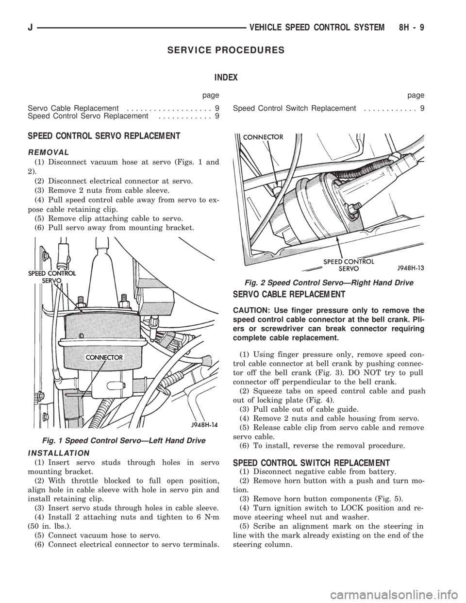
(1) Disconnect vacuum hose at servo (Figs. 1 and
2).
(2) Disconnect electrical connector at servo.
(3) Remove 2 nuts from cable sleeve.
(4) Pull speed control cable away from servo to ex-
pose cable retaining clip.
(5) Remove clip attaching cable to servo.
(6) Pull servo away from mounting bracket.
INSTALLATION
(1) Insert servo studs through holes in servo
mounting bracket.
(2) With throttle blocked to full open position,
align hole in cable sleeve with hole in servo pin and
install retaining clip.
(3)
Insert servo studs through holes in cable sleeve.
(4) Install 2 attaching nuts and tighten to 6 Nzm
(50 in. lbs.).
(5) Connect vacuum hose to servo.
(6) Connect electrical connector to servo terminals.
SERVO CABLE REPLACEMENT
CAUTION: Use finger pressure only to remove the
speed control cable connector at the bell crank. Pli-
ers or screwdriver can break connector requiring
complete cable replacement.
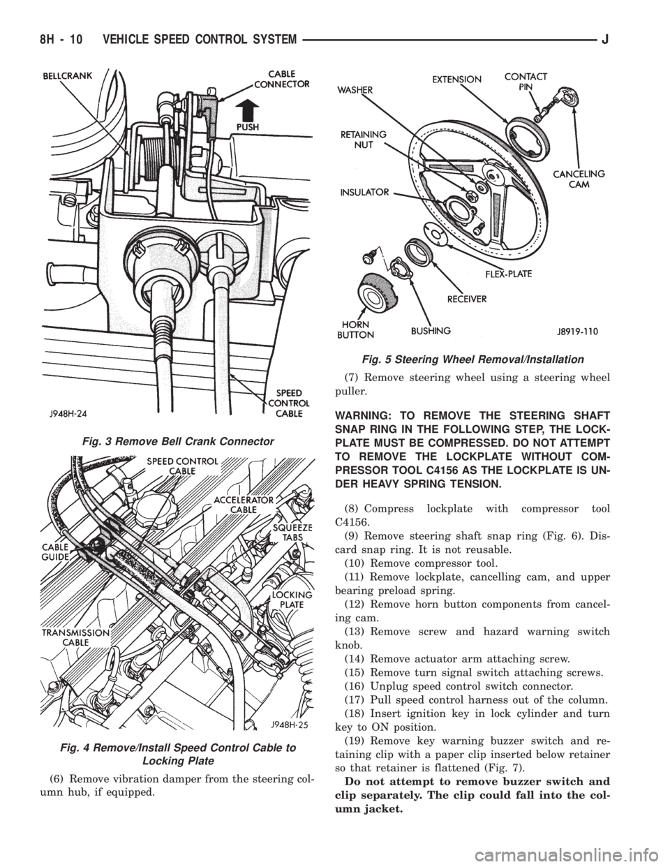
(1) Using finger pressure only, remove speed con-
trol cable connector at bell crank by pushing connec-
tor off the bell crank (Fig. 3). DO NOT try to pull
connector off perpendicular to the bell crank.
(2) Squeeze tabs on speed control cable and push
out of locking plate (Fig. 4).
(3) Pull cable out of cable guide.
(4) Remove 2 nuts and cable housing from servo.
(5) Release cable clip from servo cable and remove
servo cable.
(6) To install, reverse the removal procedure.
SPEED CONTROL SWITCH REPLACEMENT
(1) Disconnect negative cable from battery.
(2) Remove horn button with a push and turn mo-
tion.
(3) Remove horn button components (Fig. 5).
(4) Turn ignition switch to LOCK position and re-
move steering wheel nut and washer.
(5) Scribe an alignment mark on the steering in
line with the mark already existing on the end of the
steering column.
Fig. 2 Speed Control ServoÐRight Hand Drive
Fig. 1 Speed Control ServoÐLeft Hand Drive
JVEHICLE SPEED CONTROL SYSTEM 8H - 9
Page 399 of 1784
(6) Remove vibration damper from the steering col-
umn hub, if equipped.(7) Remove steering wheel using a steering wheel
puller.
WARNING: TO REMOVE THE STEERING SHAFT
SNAP RING IN THE FOLLOWING STEP, THE LOCK-
PLATE MUST BE COMPRESSED. DO NOT ATTEMPT
TO REMOVE THE LOCKPLATE WITHOUT COM-
PRESSOR TOOL C4156 AS THE LOCKPLATE IS UN-
DER HEAVY SPRING TENSION.
(8) Compress lockplate with compressor tool
C4156.
(9) Remove steering shaft snap ring (Fig. 6). Dis-
card snap ring. It is not reusable.
(10) Remove compressor tool.
(11) Remove lockplate, cancelling cam, and upper
bearing preload spring.
(12) Remove horn button components from cancel-
ing cam.
(13) Remove screw and hazard warning switch
knob.
(14) Remove actuator arm attaching screw.
(15) Remove turn signal switch attaching screws.
(16) Unplug speed control switch connector.
(17) Pull speed control harness out of the column.
(18) Insert ignition key in lock cylinder and turn
key to ON position.
(19) Remove key warning buzzer switch and re-
taining clip with a paper clip inserted below retainer
so that retainer is flattened (Fig. 7).
Do not attempt to remove buzzer switch and
clip separately. The clip could fall into the col-
umn jacket.
Fig. 3 Remove Bell Crank Connector
Fig. 4 Remove/Install Speed Control Cable to
Locking Plate
Fig. 5 Steering Wheel Removal/Installation
8H - 10 VEHICLE SPEED CONTROL SYSTEMJ
Page 404 of 1784
TURN/HAZARD SWITCH REPLACEMENT - ALL MODELS
(1) Disconnect negative cable from battery.
(2) Remove the horn button with a push and turn
motion.
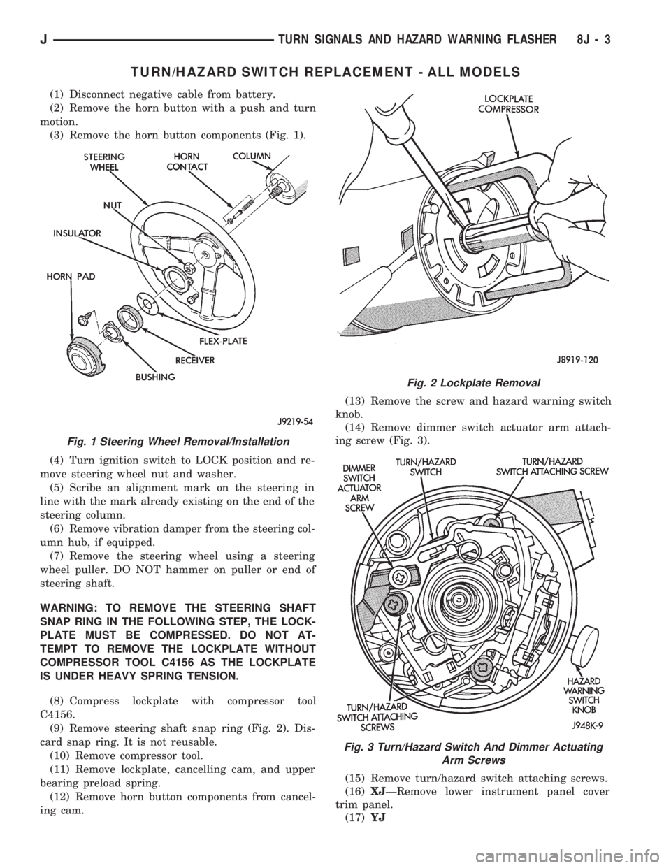
(3) Remove the horn button components (Fig. 1).
(4) Turn ignition switch to LOCK position and re-
move steering wheel nut and washer.
(5) Scribe an alignment mark on the steering in
line with the mark already existing on the end of the
steering column.
(6) Remove vibration damper from the steering col-
umn hub, if equipped.
(7) Remove the steering wheel using a steering
wheel puller. DO NOT hammer on puller or end of
steering shaft.
WARNING: TO REMOVE THE STEERING SHAFT
SNAP RING IN THE FOLLOWING STEP, THE LOCK-
PLATE MUST BE COMPRESSED. DO NOT AT-
TEMPT TO REMOVE THE LOCKPLATE WITHOUT
COMPRESSOR TOOL C4156 AS THE LOCKPLATE
IS UNDER HEAVY SPRING TENSION.
(8) Compress lockplate with compressor tool
C4156.
(9) Remove steering shaft snap ring (Fig. 2). Dis-
card snap ring. It is not reusable.
(10) Remove compressor tool.
(11) Remove lockplate, cancelling cam, and upper
bearing preload spring.
(12) Remove horn button components from cancel-
ing cam.(13) Remove the screw and hazard warning switch
knob.
(14) Remove dimmer switch actuator arm attach-
ing screw (Fig. 3).
(15) Remove turn/hazard switch attaching screws.
(16)XJÐRemove lower instrument panel cover
trim panel.
(17)YJ
Fig. 1 Steering Wheel Removal/Installation
Fig. 2 Lockplate Removal
Fig. 3 Turn/Hazard Switch And Dimmer Actuating
Arm Screws
JTURN SIGNALS AND HAZARD WARNING FLASHER 8J - 3
Page 422 of 1784
WIPER CONTROL SWITCH REPLACEMENT
(1) Disconnect negative cable from battery.
(2) Remove horn button with a push and turn mo-
tion.
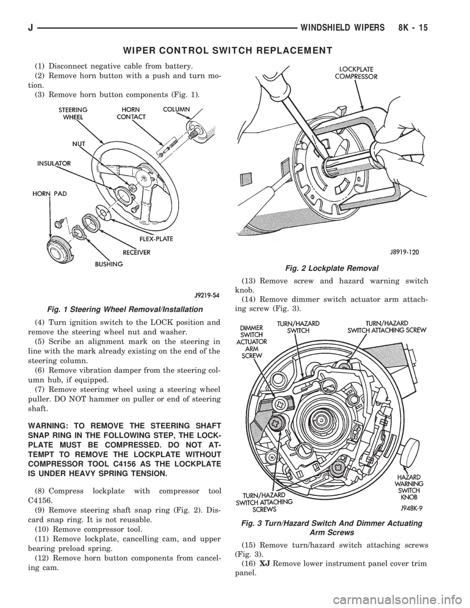
(3) Remove horn button components (Fig. 1).
(4) Turn ignition switch to the LOCK position and
remove the steering wheel nut and washer.
(5) Scribe an alignment mark on the steering in
line with the mark already existing on the end of the
steering column.
(6) Remove vibration damper from the steering col-
umn hub, if equipped.
(7) Remove steering wheel using a steering wheel
puller. DO NOT hammer on puller or end of steering
shaft.
WARNING: TO REMOVE THE STEERING SHAFT
SNAP RING IN THE FOLLOWING STEP, THE LOCK-
PLATE MUST BE COMPRESSED. DO NOT AT-
TEMPT TO REMOVE THE LOCKPLATE WITHOUT
COMPRESSOR TOOL C4156 AS THE LOCKPLATE
IS UNDER HEAVY SPRING TENSION.
(8) Compress lockplate with compressor tool
C4156.
(9) Remove steering shaft snap ring (Fig. 2). Dis-
card snap ring. It is not reusable.
(10) Remove compressor tool.
(11) Remove lockplate, cancelling cam, and upper
bearing preload spring.
(12) Remove horn button components from cancel-
ing cam.(13) Remove screw and hazard warning switch
knob.
(14) Remove dimmer switch actuator arm attach-
ing screw (Fig. 3).
(15) Remove turn/hazard switch attaching screws
(Fig. 3).
(16)XJRemove lower instrument panel cover trim
panel.
Fig. 1 Steering Wheel Removal/Installation
Fig. 2 Lockplate Removal
Fig. 3 Turn/Hazard Switch And Dimmer Actuating
Arm Screws
JWINDSHIELD WIPERS 8K - 15