1994 JEEP CHEROKEE load capacity
[x] Cancel search: load capacityPage 53 of 1784
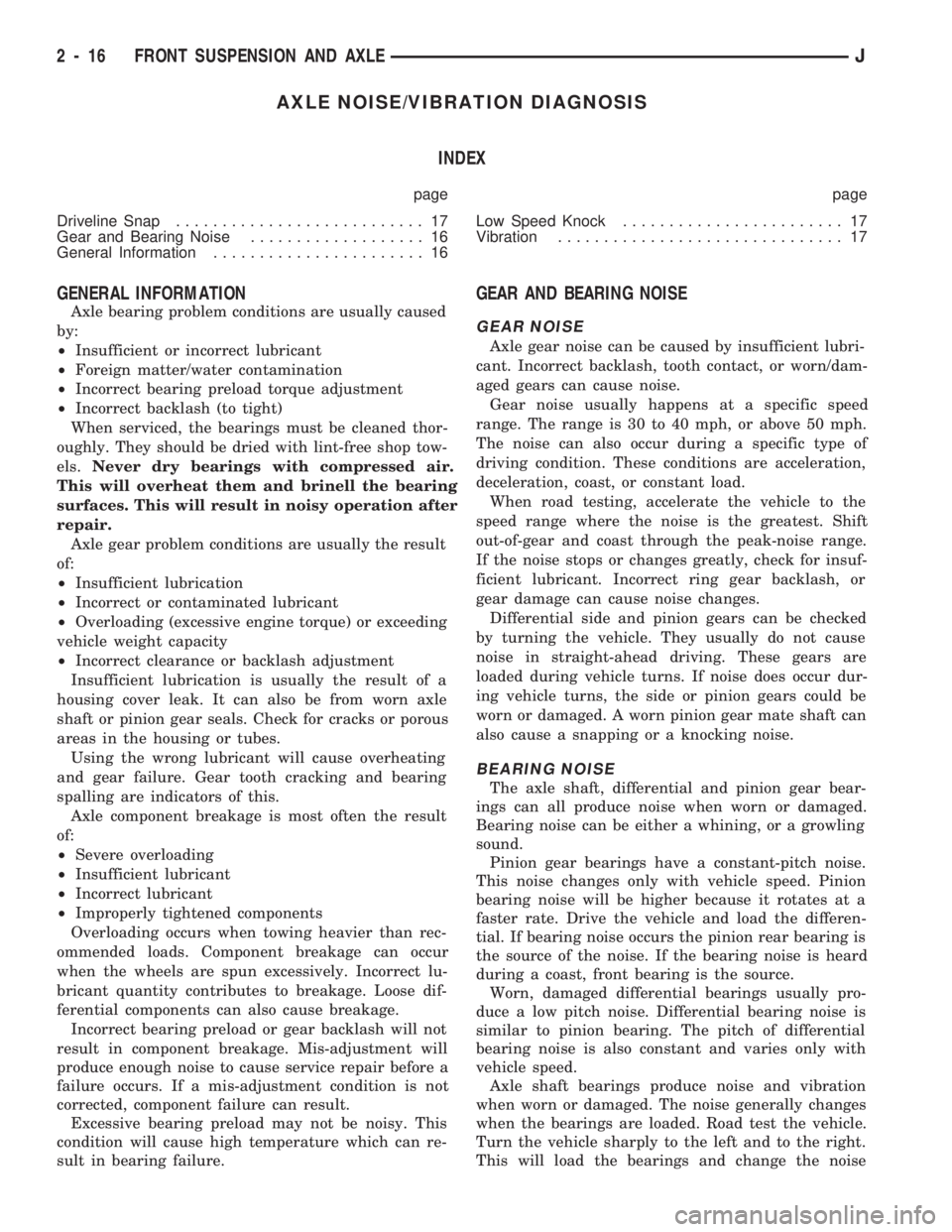
AXLE NOISE/VIBRATION DIAGNOSIS
INDEX
page page
Driveline Snap........................... 17
Gear and Bearing Noise................... 16
General Information....................... 16Low Speed Knock........................ 17
Vibration............................... 17
GENERAL INFORMATION
Axle bearing problem conditions are usually caused
by:
²Insufficient or incorrect lubricant
²Foreign matter/water contamination
²Incorrect bearing preload torque adjustment
²Incorrect backlash (to tight)
When serviced, the bearings must be cleaned thor-
oughly. They should be dried with lint-free shop tow-
els.Never dry bearings with compressed air.
This will overheat them and brinell the bearing
surfaces. This will result in noisy operation after
repair.
Axle gear problem conditions are usually the result
of:
²Insufficient lubrication
²Incorrect or contaminated lubricant
²Overloading (excessive engine torque) or exceeding
vehicle weight capacity
²Incorrect clearance or backlash adjustment
Insufficient lubrication is usually the result of a
housing cover leak. It can also be from worn axle
shaft or pinion gear seals. Check for cracks or porous
areas in the housing or tubes.
Using the wrong lubricant will cause overheating
and gear failure. Gear tooth cracking and bearing
spalling are indicators of this.
Axle component breakage is most often the result
of:
²Severe overloading
²Insufficient lubricant
²Incorrect lubricant
²Improperly tightened components
Overloading occurs when towing heavier than rec-
ommended loads. Component breakage can occur
when the wheels are spun excessively. Incorrect lu-
bricant quantity contributes to breakage. Loose dif-
ferential components can also cause breakage.
Incorrect bearing preload or gear backlash will not
result in component breakage. Mis-adjustment will
produce enough noise to cause service repair before a
failure occurs. If a mis-adjustment condition is not
corrected, component failure can result.
Excessive bearing preload may not be noisy. This
condition will cause high temperature which can re-
sult in bearing failure.
GEAR AND BEARING NOISE
GEAR NOISE
Axle gear noise can be caused by insufficient lubri-
cant. Incorrect backlash, tooth contact, or worn/dam-
aged gears can cause noise.
Gear noise usually happens at a specific speed
range. The range is 30 to 40 mph, or above 50 mph.
The noise can also occur during a specific type of
driving condition. These conditions are acceleration,
deceleration, coast, or constant load.
When road testing, accelerate the vehicle to the
speed range where the noise is the greatest. Shift
out-of-gear and coast through the peak-noise range.
If the noise stops or changes greatly, check for insuf-
ficient lubricant. Incorrect ring gear backlash, or
gear damage can cause noise changes.
Differential side and pinion gears can be checked
by turning the vehicle. They usually do not cause
noise in straight-ahead driving. These gears are
loaded during vehicle turns. If noise does occur dur-
ing vehicle turns, the side or pinion gears could be
worn or damaged. A worn pinion gear mate shaft can
also cause a snapping or a knocking noise.
BEARING NOISE
The axle shaft, differential and pinion gear bear-
ings can all produce noise when worn or damaged.
Bearing noise can be either a whining, or a growling
sound.
Pinion gear bearings have a constant-pitch noise.
This noise changes only with vehicle speed. Pinion
bearing noise will be higher because it rotates at a
faster rate. Drive the vehicle and load the differen-
tial. If bearing noise occurs the pinion rear bearing is
the source of the noise. If the bearing noise is heard
during a coast, front bearing is the source.
Worn, damaged differential bearings usually pro-
duce a low pitch noise. Differential bearing noise is
similar to pinion bearing. The pitch of differential
bearing noise is also constant and varies only with
vehicle speed.
Axle shaft bearings produce noise and vibration
when worn or damaged. The noise generally changes
when the bearings are loaded. Road test the vehicle.
Turn the vehicle sharply to the left and to the right.
This will load the bearings and change the noise
2 - 16 FRONT SUSPENSION AND AXLEJ
Page 253 of 1784

The coolant reserve/overflow system consists of a
radiator mounted pressurized cap, a plastic reserve/
overflow tank (Figs. 21, 22 or 23), a tube connecting
the radiator and tank, and an overflow tube on the
side of the tank.
TANK REMOVAL/INSTALLATION
(1) Remove the tube clamp at the tank and remove
tube.(2) On YJ models, remove the windshield washer
reservoir and its mounting bracket.
(3) Remove the tank mounting bolts and remove
tank.
(4) Reverse the preceding steps for installation.
RADIATOR PRESSURE CAP
All radiators are equipped with a pressure cap.
This cap releases pressure at some point within a
range of 83-110 kPa (12-16 psi). The pressure relief
point (in pounds) is engraved on top of the cap (Fig.
24).
The cooling system will operate at pressures
slightly above atmospheric pressure. This results in a
higher coolant boiling point allowing increased radi-
ator cooling capacity. The cap (Fig. 24) contains a
spring-loaded pressure relief valve. This valve opens
when system pressure reaches the release range of
83-110 kPa (12-16 psi).
A vent valve in the center of the cap allows a small
coolant flow through the cap when coolant is below
boiling temperature. The valve is completely closed
when boiling point is reached. As coolant cools, it
contracts and creates a vacuum in the cooling sys-
tem. This causes the vacuum valve to open and cool-
ant in reserve/overflow tank to be drawn through
connecting hose into radiator. If the vacuum valve is
stuck shut, radiator hoses will collapse on cool-down.
A rubber gasket seals the radiator filler neck. This
is done to maintain vacuum during coolant cool-down
and to prevent leakage when system is under pres-
sure.
Fig. 21 Reserve/Overflow TankÐYJ Models
Fig. 22 Reserve/Overflow TankÐXJ ModelsÐExcept
Right Hand Drive
Fig. 23 Reserve/Overflow TankÐXJ ModelsÐWith
Right Hand Drive
7 - 20 COOLING SYSTEMJ
Page 277 of 1784
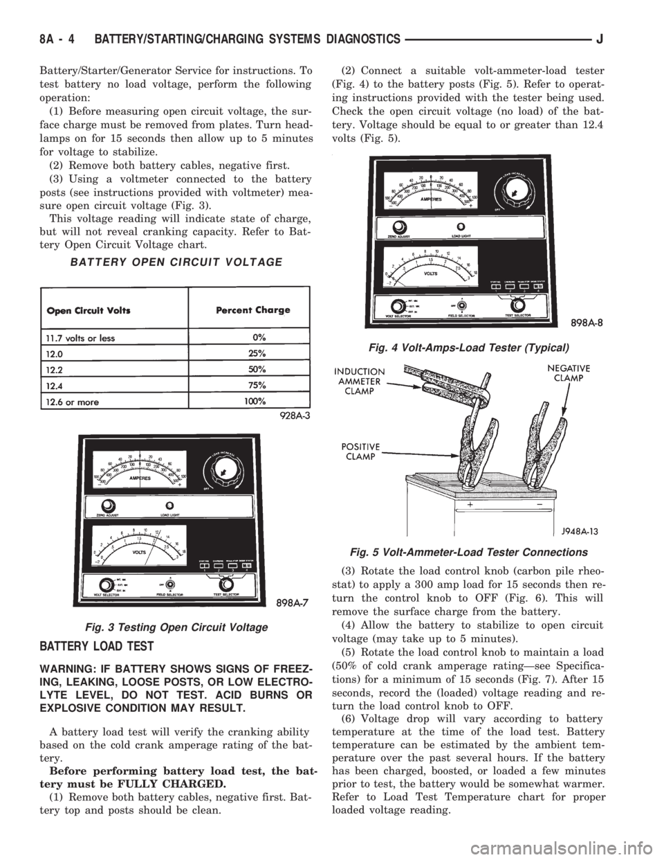
Battery/Starter/Generator Service for instructions. To
test battery no load voltage, perform the following
operation:
(1) Before measuring open circuit voltage, the sur-
face charge must be removed from plates. Turn head-
lamps on for 15 seconds then allow up to 5 minutes
for voltage to stabilize.
(2) Remove both battery cables, negative first.
(3) Using a voltmeter connected to the battery
posts (see instructions provided with voltmeter) mea-
sure open circuit voltage (Fig. 3).
This voltage reading will indicate state of charge,
but will not reveal cranking capacity. Refer to Bat-
tery Open Circuit Voltage chart.
BATTERY LOAD TEST
WARNING: IF BATTERY SHOWS SIGNS OF FREEZ-
ING, LEAKING, LOOSE POSTS, OR LOW ELECTRO-
LYTE LEVEL, DO NOT TEST. ACID BURNS OR
EXPLOSIVE CONDITION MAY RESULT.
A battery load test will verify the cranking ability
based on the cold crank amperage rating of the bat-
tery.
Before performing battery load test, the bat-
tery must be FULLY CHARGED.
(1) Remove both battery cables, negative first. Bat-
tery top and posts should be clean.(2) Connect a suitable volt-ammeter-load tester
(Fig. 4) to the battery posts (Fig. 5). Refer to operat-
ing instructions provided with the tester being used.
Check the open circuit voltage (no load) of the bat-
tery. Voltage should be equal to or greater than 12.4
volts (Fig. 5).
(3) Rotate the load control knob (carbon pile rheo-
stat) to apply a 300 amp load for 15 seconds then re-
turn the control knob to OFF (Fig. 6). This will
remove the surface charge from the battery.
(4) Allow the battery to stabilize to open circuit
voltage (may take up to 5 minutes).
(5) Rotate the load control knob to maintain a load
(50% of cold crank amperage ratingÐsee Specifica-
tions) for a minimum of 15 seconds (Fig. 7). After 15
seconds, record the (loaded) voltage reading and re-
turn the load control knob to OFF.
(6) Voltage drop will vary according to battery
temperature at the time of the load test. Battery
temperature can be estimated by the ambient tem-
perature over the past several hours. If the battery
has been charged, boosted, or loaded a few minutes
prior to test, the battery would be somewhat warmer.
Refer to Load Test Temperature chart for proper
loaded voltage reading.
Fig. 4 Volt-Amps-Load Tester (Typical)
Fig. 5 Volt-Ammeter-Load Tester Connections
BATTERY OPEN CIRCUIT VOLTAGE
Fig. 3 Testing Open Circuit Voltage
8A - 4 BATTERY/STARTING/CHARGING SYSTEMS DIAGNOSTICSJ
Page 278 of 1784
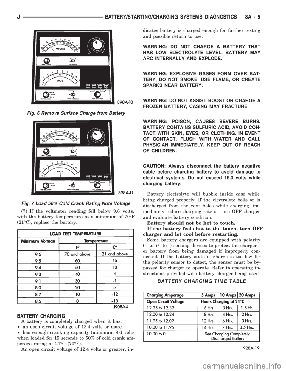
(7) If the voltmeter reading fell below 9.6 volts,
with the battery temperature at a minimum of 70ÉF
(21ÉC), replace the battery.
BATTERY CHARGING
A battery is completely charged when it has:
²an open circuit voltage of 12.4 volts or more.
²has enough cranking capacity (minimum 9.6 volts
when loaded for 15 seconds to 50% of cold crank am-
perage rating at 21ÉC (70ÉF).
An open circuit voltage of 12.4 volts or greater, in-dicates battery is charged enough for further testing
and possible return to use.
WARNING: DO NOT CHARGE A BATTERY THAT
HAS LOW ELECTROLYTE LEVEL. BATTERY MAY
ARC INTERNALLY AND EXPLODE.
WARNING: EXPLOSIVE GASES FORM OVER BAT-
TERY, DO NOT SMOKE, USE FLAME, OR CREATE
SPARKS NEAR BATTERY.
WARNING: DO NOT ASSIST BOOST OR CHARGE A
FROZEN BATTERY, CASING MAY FRACTURE.
WARNING: POISON, CAUSES SEVERE BURNS.
BATTERY CONTAINS SULFURIC ACID, AVOID CON-
TACT WITH SKIN, EYES, OR CLOTHING. IN EVENT
OF CONTACT, FLUSH WITH WATER AND CALL
PHYSICIAN IMMEDIATELY. KEEP OUT OF REACH
OF CHILDREN.
CAUTION: Always disconnect the battery negative
cable before charging battery to avoid damage to
electrical systems. Do not exceed 16.0 volts while
charging battery.
Battery electrolyte will bubble inside case while
being charged properly. If the electrolyte boils or is
discharged from the vent holes while charging, im-
mediately reduce charging rate or turn OFF charger
and evaluate battery condition.
Battery should not be hot to touch.
If the battery feels hot to the touch, turn OFF
charger and let cool before restarting.
Some battery chargers are equipped with polarity
(+ to +/- to -) sensing devices to protect the charger
or battery from being damaged if improperly con-
nected. If the battery state of charge is too low for
the polarity sensor to detect, the sensor must be by-
passed for charger to operate. Refer to operating in-
structions provided with battery charger being used.
Fig. 6 Remove Surface Charge from Battery
Fig. 7 Load 50% Cold Crank Rating Note Voltage
BATTERY CHARGING TIME TABLE
JBATTERY/STARTING/CHARGING SYSTEMS DIAGNOSTICS 8A - 5
Page 279 of 1784
After the battery has been charged to 12.4 volts or
greater, perform a load test to determine cranking
capacity. If the battery will endure a load test, re-
turn the battery to use. If battery will not endure a
load test, it must be replaced. Clean and inspect bat-
tery holddowns, tray, terminals, posts, and top before
completing service, see Group 8B - Battery/Starter/
Generator Service.
CHARGING TIME REQUIRED
The time required to charge a battery will vary de-
pending upon the following factors:
(1)Size of BatteryÐA completely discharged
large, heavy-duty battery requires more than twice
the recharging time as a completely discharged small
capacity battery.
WARNING: NEVER EXCEED 20 AMPS WHEN
CHARGING A COLD (-1ÉC/30ÉF) BATTERY, PER-
SONAL INJURY MAY RESULT.
(2)TemperatureÐA longer time will be needed
to charge a battery at -18ÉC (0ÉF) than at 27ÉC
(80ÉF). When a fast charger is connected to a cold
battery, current accepted by battery will be very low
at first. Then, in time, the battery will accept a
higher rate as battery warms.
(3)Charger CapacityÐA charger, that supplies
only 5 amperes, will require a longer charging time
than a charger that supplies 20 amperes or more.
(4)State Of ChargeÐA completely discharged
battery requires more charging time than a partially
charged battery. Electrolyte is nearly pure water in a
completely discharged battery. At first the charging
current amperage will be low. As the battery charges
the specific gravity of the electrolyte will rise slowly.
CHARGING COMPLETELY DISCHARGED
BATTERY
The following procedure should be used to recharge
a completely discharged battery. Unless procedure is
properly followed, a good battery may be needlessly
replaced.
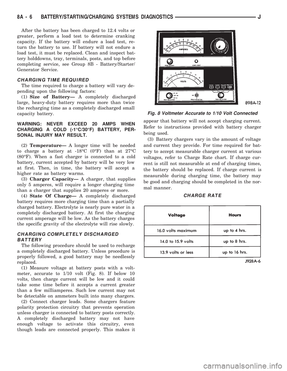
(1) Measure voltage at battery posts with a volt-
meter, accurate to 1/10 volt (Fig. 8). If below 10
volts, then charge current will be low and it could
take some time before it accepts a current greater
than a few milliamperes. Such low current may not
be detectable on ammeters built into many chargers.
(2) Connect charger leads. Some chargers feature
polarity protection circuitry that prevents operation
unless charger is connected to battery posts correctly.
A completely discharged battery may not have
enough voltage to activate this circuitry, even
though leads are connected properly. This makes itappear that battery will not accept charging current.
Refer to instructions provided with battery charger
being used.
(3) Battery chargers vary in the amount of voltage
and current they provide. For time required for bat-
tery to accept measurable charger current at various
voltages, refer to Charge Rate chart. If charge cur-
rent is still not measurable at end of charging times,
the battery should be replaced. If charge current is
measurable during charging time, the battery may
be good and charging should be completed in the nor-
mal manner.
Fig. 8 Voltmeter Accurate to 1/10 Volt Connected
CHARGE RATE
8A - 6 BATTERY/STARTING/CHARGING SYSTEMS DIAGNOSTICSJ
Page 1445 of 1784
TIRE CHAINS
Tire snow chains may be used on certain models.
Refer to Owner's Manual for more information.
CLEANING OF TIRES
Steam cleaning may be used for cleaning.
DO NOT use gasoline or wire brush for cleaning.
DO NOT use mineral oil or an oil-based solvent.
PRESSURE GAUGES
High-quality, dial-type, air-pressure gauges are
recommended. After checking with the gauge, re-
place valve cap and finger tight.
TIRE INFLATION PRESSURES
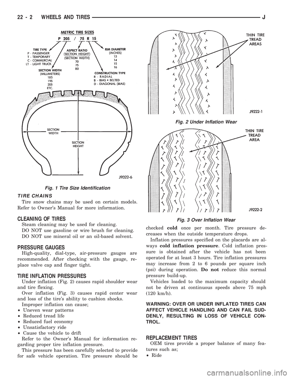
Under inflation (Fig. 2) causes rapid shoulder wear
and tire flexing.
Over inflation (Fig. 3) causes rapid center wear
and loss of the tire's ability to cushion shocks.
Improper inflation can cause;
²Uneven wear patterns
²Reduced tread life
²Reduced fuel economy
²Unsatisfactory ride
²Cause the vehicle to drift
Refer to the Owner's Manual for information re-
garding proper tire inflation pressure.
This pressure has been carefully selected to provide
for safe vehicle operation. Tire pressure should becheckedcoldonce per month. Tire pressure de-
creases when the outside temperature drops.
Inflation pressures specified on the placards are al-
wayscold inflation pressure. Cold inflation pres-
sure is obtained after the vehicle has not been
operated for at least 3 hours. Tire inflation pressures
may increase from 2 to 6 pounds per square inch
(psi) during operation.Do notreduce this normal
pressure build-up.
Vehicles loaded to the maximum capacity should
not be driven at continuous speeds above 75 mph
(120 km/h).
WARNING: OVER OR UNDER INFLATED TIRES CAN
AFFECT VEHICLE HANDLING AND CAN FAIL SUD-
DENLY, RESULTING IN LOSS OF VEHICLE CON-
TROL.
REPLACEMENT TIRES
OEM tires provide a proper balance of many fea-
tures such as;
²Ride
Fig. 1 Tire Size Identification
Fig. 2 Under Inflation Wear
Fig. 3 Over Inflation Wear
22 - 2 WHEELS AND TIRESJ
Page 1449 of 1784
WHEELS
GENERAL INFORMATION
Original equipment wheels are designed for the
specified Maximum Vehicle Capacity.
All models use steel or cast aluminum drop center
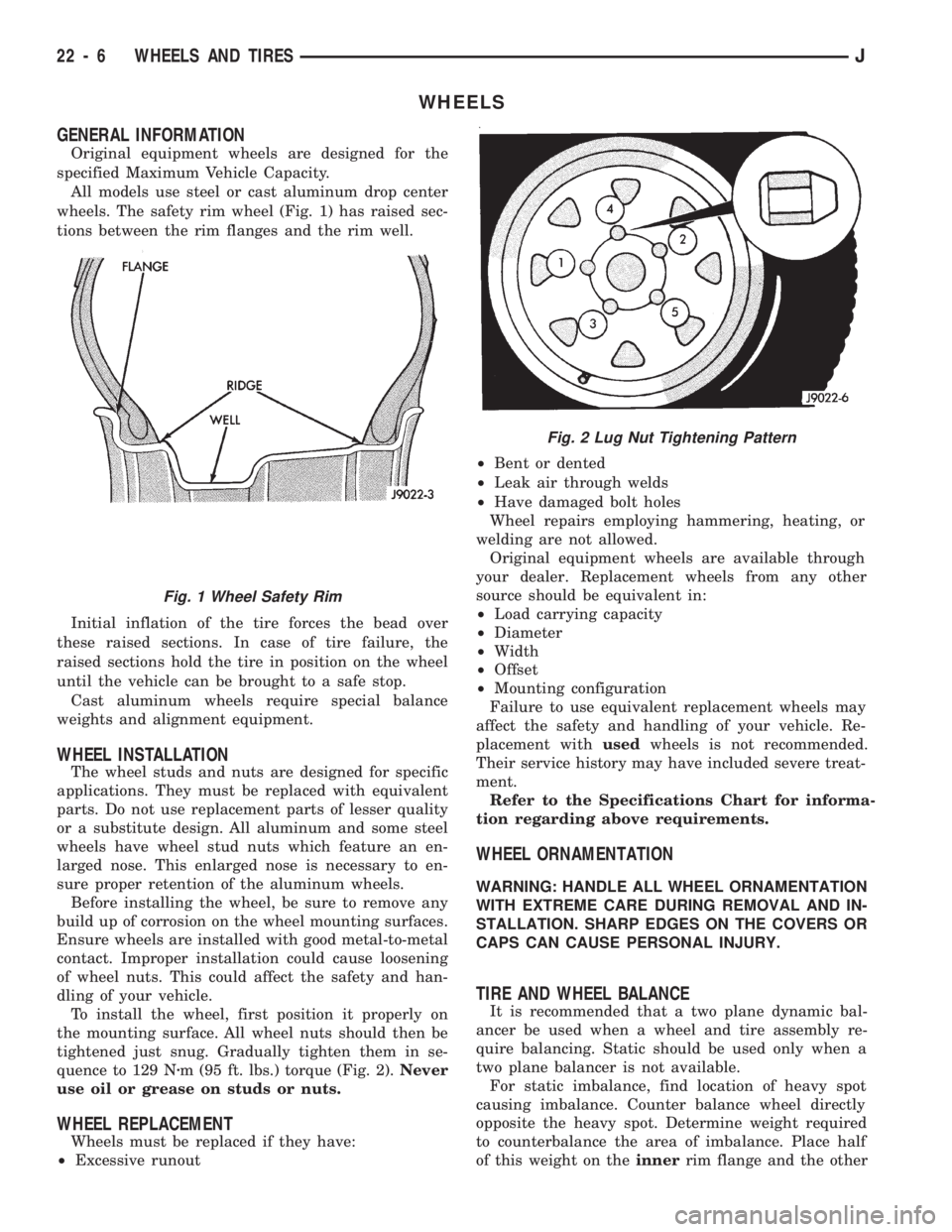
wheels. The safety rim wheel (Fig. 1) has raised sec-
tions between the rim flanges and the rim well.
Initial inflation of the tire forces the bead over
these raised sections. In case of tire failure, the
raised sections hold the tire in position on the wheel
until the vehicle can be brought to a safe stop.
Cast aluminum wheels require special balance
weights and alignment equipment.
WHEEL INSTALLATION
The wheel studs and nuts are designed for specific
applications. They must be replaced with equivalent
parts. Do not use replacement parts of lesser quality
or a substitute design. All aluminum and some steel
wheels have wheel stud nuts which feature an en-
larged nose. This enlarged nose is necessary to en-
sure proper retention of the aluminum wheels.
Before installing the wheel, be sure to remove any
build up of corrosion on the wheel mounting surfaces.
Ensure wheels are installed with good metal-to-metal
contact. Improper installation could cause loosening
of wheel nuts. This could affect the safety and han-
dling of your vehicle.
To install the wheel, first position it properly on
the mounting surface. All wheel nuts should then be
tightened just snug. Gradually tighten them in se-
quence to 129 Nzm (95 ft. lbs.) torque (Fig. 2).Never
use oil or grease on studs or nuts.
WHEEL REPLACEMENT
Wheels must be replaced if they have:
²Excessive runout²Bent or dented
²Leak air through welds
²Have damaged bolt holes
Wheel repairs employing hammering, heating, or
welding are not allowed.
Original equipment wheels are available through
your dealer. Replacement wheels from any other
source should be equivalent in:
²Load carrying capacity
²Diameter
²Width
²Offset
²Mounting configuration
Failure to use equivalent replacement wheels may
affect the safety and handling of your vehicle. Re-
placement withusedwheels is not recommended.
Their service history may have included severe treat-
ment.
Refer to the Specifications Chart for informa-
tion regarding above requirements.
WHEEL ORNAMENTATION
WARNING: HANDLE ALL WHEEL ORNAMENTATION
WITH EXTREME CARE DURING REMOVAL AND IN-
STALLATION. SHARP EDGES ON THE COVERS OR
CAPS CAN CAUSE PERSONAL INJURY.
TIRE AND WHEEL BALANCE
It is recommended that a two plane dynamic bal-
ancer be used when a wheel and tire assembly re-
quire balancing. Static should be used only when a
two plane balancer is not available.
For static imbalance, find location of heavy spot
causing imbalance. Counter balance wheel directly
opposite the heavy spot. Determine weight required
to counterbalance the area of imbalance. Place half
of this weight on theinnerrim flange and the other
Fig. 2 Lug Nut Tightening Pattern
Fig. 1 Wheel Safety Rim
22 - 6 WHEELS AND TIRESJ
Page 1767 of 1784
TEMPERATURE SENSOR TEST, ENGINE
COOLANT; FUEL SYSTEM..............14-43
TEMPERATURE SENSOR TEST, ENGINE
COOLANT; IGNITION SYSTEMS..........8D-12
TEMPERATURE SENSOR TEST, INTAKE
AIR ...............................14-43
TEMPERATURE SENSOR TEST, INTAKE
MANIFOLD AIR......................8D-14
TENSION, BELT.......................8B-10
TENSION, DRIVE BELT...............7-33,7-38
TENSIONÐRIGHT HAND DRIVE
(RHD),BELT..........................7-34
TENSION SPECIFICATIONS, BELT...........7-34
TENSIONER REPLACEMENT (XJ), PARKING
BRAKE CABLE........................5-61
TENSIONERÐXJ MODELS, AUTOMATIC
BELT ...............................7-36
TERMINAL ASSEMBLY REPLACEMENT,
CONNECTOR.........................8W-5
TERMINAL REPLACEMENT...............8W-5
TEST, A/C PERFORMANCE................24-8
TEST, ACTUATOR MOTOR STALL...........8P-6
TEST, AIR PRESSURE...................21-73
TEST, ANALYZING THE ROAD.............21-70
TEST, BATTERY LOAD...................8A-4
TEST, BATTERY OPEN CIRCUIT VOLTAGE....8A-3
TEST, CAMSHAFT POSITION SENSOR;
FUEL SYSTEM.......................14-43
TEST, CAMSHAFT POSITION SENSOR;
IGNITION SYSTEMS...................8D-8
TEST, CONVERTER STALL...............21-72
TEST, CRANKSHAFT POSITION SENSOR;
FUEL SYSTEM.......................14-44
TEST, CRANKSHAFT POSITION SENSOR;
IGNITION SYSTEMS...................8D-9
TEST, CYLINDER COMBUSTION
PRESSURE LEAKAGE...................9-6
TEST, CYLINDER COMBUSTION
PRESSURE LEAKAGE DIAGNOSIS..........9-6
TEST, CYLINDER COMPRESSION PRESSURE . . 9-5
TEST, ENGINE COOLANT TEMPERATURE
SENSOR......................8D-12,14-43
TEST, EXTENDED IDLE SWITCH...........14-45
TEST, FUEL PRESSURE LEAK DOWN........14-7
TEST, FUEL PUMP CAPACITY..............14-7
TEST, FUEL SYSTEM PRESSURE......14-5,14-48
TEST, HYDRAULIC PRESSURE......21-71,21-168
TEST, HYDROMETER....................8A-3
TEST, IDLE AIR CONTROL MOTOR........14-46
TEST, INJECTOR.......................14-48
TEST, INTAKE AIR TEMPERATURE SENSOR . . 8D-14,
14-43
TEST, MANIFOLD ABSOLUTE PRESSURE
(MAP) SENSOR.................8D-14,14-44
TEST, MANUAL SHIFTING...............21-168
TEST, MASTER CYLINDER/POWER
BOOSTER............................5-11
TEST, OXYGEN SENSOR (O2S)
HEATING ELEMENT...................14-45
TEST, POWER BOOSTER CHECK VALVE......5-11
TEST, POWER BOOSTER VACUUM..........5-12
TEST PROCEDURES, BATTERY............8A-2
TEST PROCEDURES ON VEHICLE,
ENGINE STARTER MOTOR..............8A-9
TEST PROCEDURES ON VEHICLE,
GENERATOR........................8A-14
TEST, PUMP PRESSURE.................19-3
TEST, REAR WINDOW DEFOGGER GRID.....8N-1
TEST, REFRIGERANT LEAK................24-8
TEST, ROAD; TRANSMISSION AND
TRANSFER CASE.....................21-70
TEST, ROAD; VEHICLE SPEED CONTROL
SYSTEM............................8H-5
TEST SPECIFICATIONS, 30RH/32RH
PRESSURE........................21-323
TEST, SPEED CONTROL SWITCH (TURN
SIGNAL LEVER)......................8H-7
TEST, STARTER MOTOR RELAY...........14-48
TEST, STARTING SYSTEM COLD
CRANKING...........................8A-9
TEST, STOP LAMP SPEED CONTROL
SWITCH
............................8H-7
TEST, THROTTLE POSITION SENSOR
......8D-18
TEST, THROTTLE POSITION SENSOR
(TPS)
..............................14-45
TEST, TIME LAG
......................21-169TEST, TORQUE CONVERTER CLUTCH
RELAY.............................14-45
TEST, TORQUE CONVERTER STALL.......21-169
TEST, VACUUM SUPPLY.................8H-7
TEST, VEHICLE SPEED SENSOR......8H-5,14-45
TESTING, AUTOMATIC SHUTDOWN
(ASD) RELAY........................14-43
TESTING COOLING SYSTEM FOR LEAKS.....7-18
TESTING, FUEL PUMP RELAY............14-44
TESTING GENERAL INFORMATION,
BATTERY............................8A-3
TESTING, IGNITION SWITCH.............8D-30
TESTING, POWER MIRROR SWITCH........8T-2
TESTING, REAR WIPER/WASHER
SWITCH.......................8K-7,8K-14
TESTING, SWITCH; POWER SEATS.........8R-2
TESTING, SWITCH; POWER WINDOWS......8S-5
TESTING, SWITCH; REAR WINDOW
DEFOGGER..........................8N-2
TESTING, TRANSMISSION COOLER FLOW . . 21-106
TESTING, WIPER SWITCH...............8K-19
TESTS - (VOLTAGE DROP METHOD),
STARTER FEED CIRCUIT................8A-9
TESTS, ANTENNA.......................8F-9
TESTS AT POWERTRAIN CONTROL
MODULE, ELECTRICAL.................8H-6
TESTS AT SERVO, ELECTRICAL............8H-5
TESTS, COMPRESSOR VALVE PLATEÐ
LEAK...............................24-8
TESTS, IGNITION SWITCH CONTINUITY....8D-31
TESTS, OXYGEN SENSOR...............8D-19
TESTS, STARTER CONTROL CIRCUIT......8A-11
TESTS, VEHICLE SPEED CONTROL
SYSTEM............................8H-5
TESTS, WATER PUMP....................7-9
THERMOMETER AND SENSOR SYSTEM
REPAIR PROCEDURES.................8C-6
THERMOSTAT..........................7-13
THERMOSTAT, TEMPERATURE CONTROL . . . 24-35
THICKNESS, AW-4 CLUTCH DISC AND
PLATE ............................21-325
THICKNESS, DISC BRAKE ROTOR..........5-31
THICKNESS VARIATION, DISC BRAKE
ROTOR.............................5-31
THIRD GEAR (CONVERTER CLUTCH
ENGAGED), HYDRAULIC FLOW IN.......21-90
THIRD GEAR, HYDRAULIC FLOW IN D
RANGE.............................21-89
THREAD NOTATIONÐSAE AND METRIC . . INTRO.-9
THREADS, REPAIR DAMAGED OR WORN.....9-4
THROTTLE 3-2 DOWNSHIFT, HYDRAULIC
FLOW DURING FULL..................21-92
THROTTLE 3-2 DOWNSHIFT, HYDRAULIC
FLOW DURING PART..................21-91
THROTTLE BODY; FUEL SYSTEM.....14-29,14-59
THROTTLE CABLE.....................14-16
THROTTLE CABLE, ACCELERATOR PEDAL . . 14-16,
14-54
THROTTLE CABLE ADJUSTMENT,
TRANSMISSION.....................21-185
THROTTLE CABLE ADJUSTMENT,
TRANSMISSION......................21-98
THROTTLE CABLE REPLACEMENT,
TRANSMISSION.....................21-184
THROTTLE POSITION SENSOR............8D-6
THROTTLE POSITION SENSOR TEST.......8D-18
THROTTLE POSITION SENSOR (TPS);
FUEL SYSTEM.......................14-59
THROTTLE POSITION SENSOR (TPS);
IGNITION SYSTEMS..................8D-29
THROTTLE POSITION SENSOR (TPS)
SERVICE..........................21-184
THROTTLE POSITION SENSOR (TPS)
TEST..............................14-45
THROTTLE POSITION SENSOR (TPS)Ð
PCM INPUT.........................14-23
THROTTLE VALVE CABLE ADJUSTMENT,
TRANSMISSION......................21-70
TIE ROD ........................19-14,19-17
TIGHTENING, WHEEL NUT............5-32,5-37
TILT STEERING COLUMN................19-59
TIME LAG TEST
......................21-169
TIMING CASE COVER
................9-27,9-67
TIMING CASE COVER OIL SEAL
REPLACEMENT
...................9-26,9-67
TIMING CHAIN AND SPROCKETS
......9-28,9-68TIMING, IGNITION.....................8D-14
TIMING, VALVE.....................9-26,9-66
TIPS, TRANSMISSION ASSEMBLY........21-146
TIRE AND WHEEL BALANCE..............22-6
TIRE AND WHEEL RUNOUT...............22-8
TIRE CARRIER, EXTERNAL SPARE/WHEEL . 23-172
TIRE INFLATION PRESSURE LABEL.....INTRO.-3
TIRE INFLATION PRESSURES.............22-2
TIRE NOISE OR VIBRATION...............22-4
TIRE WEAR PATTERNS..................22-4
TIRES; LUBRICATION AND MAINTENANCE....0-34
TIRES................................22-1
TIRES, CLEANING OF....................22-2
TIRES, REPLACEMENT...................22-2
TIRE/WHEEL HOLDDOWN AND FLOOR
BRACKETS.........................23-128
TOOL, DRB SCAN; COOLING SYSTEM........7-5
TOOL, DRB SCAN; EMISSION CONTROL
SYSTEMS...........................25-2
TOOL, DRB SCAN; FUEL SYSTEM.........14-51
TOOL, DRB SCAN; IGNITION SYSTEMS.....8D-10
TOP REPAIR, HARD...................23-165
TOP ROOF VENT......................23-165
TOP SERVICE............23-164,23-166,23-167
TORQUE; COOLING SYSTEM..............7-39
TORQUE; FUEL SYSTEM................14-62
TORQUE; IGNITION SYSTEMS............8D-33
TORQUE, COLLISION DAMAGE............13-1
TORQUE CONVERSION..............INTRO.-10
TORQUE CONVERTER; TRANSMISSION
AND TRANSFER CASE...........21-66,21-158
TORQUE CONVERTER CLUTCH RELAY......14-60
TORQUE CONVERTER CLUTCH RELAY
TEST..............................14-45
TORQUE CONVERTER CLUTCH RELAYÐ
PCM OUTPUT.......................14-27
TORQUE CONVERTER INSTALLATION,
TRANSMISSION.....................21-190
TORQUE CONVERTER REMOVAL,
TRANSMISSION.....................21-189
TORQUE CONVERTER STALL TEST.......21-169
TORQUE CONVERTER STATOR CLUTCH
INSPECTION.......................21-189
TORQUE SPECIFICATIONS, 30RH/32RH....21-323
TORQUE SPECIFICATIONSÐ AX 15
MANUAL TRANSMISSION.............21-320
TORQUE SPECIFICATIONSÐACCESSORIES . 23-208
TORQUE SPECIFICATIONS, AW-4
.........21-331
TORQUE SPECIFICATIONS, BATTERY
.......8B-10
TORQUE SPECIFICATIONS; BATTERY/
STARTER/GENERATOR SERVICE
.........8B-12
TORQUE SPECIFICATIONS, BRAKE
..........5-67
TORQUE SPECIFICATIONS; CLUTCH
........6-17
TORQUE SPECIFICATIONS; ELECTRICAL
.....8A-8
TORQUE SPECIFICATIONS; ENGINES
....9-49,9-89
TORQUE SPECIFICATIONS; EXHAUST
SYSTEM AND INTAKE MANIFOLD
........11-10
TORQUE SPECIFICATIONS; FRONT
SUSPENSION AND AXLE
................2-47
TORQUE SPECIFICATIONS; HEATING AND
AIR CONDITIONING
...................24-45
TORQUE SPECIFICATIONS; HORNS
.........8G-3
TORQUE SPECIFICATIONS;
INTRODUCTION
...................INTRO.-8
TORQUE SPECIFICATIONS, NP231/NP242
. . 21-331
TORQUE SPECIFICATIONS; PROPELLER
SHAFTS
............................16-14
TORQUE SPECIFICATIONS; REAR
SUSPENSION AND AXLES
...............3-50
TORQUE SPECIFICATIONS, STARTER
MOTOR
............................8B-11
TORQUE SPECIFICATIONS; STEERING
......19-73
TORQUE SPECIFICATIONS XJ
.............8K-7
TORQUE SPECIFICATIONSÐXJ VEHICLES
. . 23-207
TORQUE VALUES, STANDARD
.........INTRO.-9
TOW HOOKÐXJ VEHICLES, REAR
.........23-87
TOW HOOKS
..........................13-14
TOW HOOKS, FRONT
....................13-5
TOWING, JUMP STARTING, HOISTING
.......0-7
TOWING RECOMMENDATIONS
..............0-8
TRACK BAR
....................2-10,2-13,3-6
TRACKS, BUCKET SEAT PLATFORM
.......23-105
TRAC-LOK DIFFERENTIAL
................3-44
JINDEX23
Description Group-Page Description Group-Page Description Group-Page