1994 JEEP CHEROKEE height
[x] Cancel search: heightPage 23 of 1784
DRIVETRAIN
INDEX
page page
Automatic Transmission.................... 23
Drive Shafts............................ 27
Front and Rear Axles..................... 26
Hydraulic Clutch......................... 22Manual Transmission...................... 22
Rubber and Plastic Hoses/Tubing............ 28
Transfer Case........................... 25
HYDRAULIC CLUTCH
RECOMMENDED MAINTENANCE
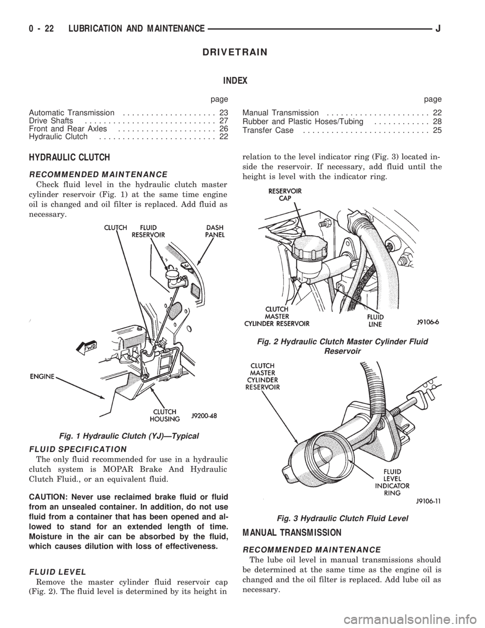
Check fluid level in the hydraulic clutch master
cylinder reservoir (Fig. 1) at the same time engine
oil is changed and oil filter is replaced. Add fluid as
necessary.
FLUID SPECIFICATION
The only fluid recommended for use in a hydraulic
clutch system is MOPAR Brake And Hydraulic
Clutch Fluid., or an equivalent fluid.
CAUTION: Never use reclaimed brake fluid or fluid
from an unsealed container. In addition, do not use
fluid from a container that has been opened and al-
lowed to stand for an extended length of time.
Moisture in the air can be absorbed by the fluid,
which causes dilution with loss of effectiveness.
FLUID LEVEL
Remove the master cylinder fluid reservoir cap
(Fig. 2). The fluid level is determined by its height inrelation to the level indicator ring (Fig. 3) located in-
side the reservoir. If necessary, add fluid until the
height is level with the indicator ring.
MANUAL TRANSMISSION
RECOMMENDED MAINTENANCE
The lube oil level in manual transmissions should
be determined at the same time as the engine oil is
changed and the oil filter is replaced. Add lube oil as
necessary.
Fig. 1 Hydraulic Clutch (YJ)ÐTypical
Fig. 2 Hydraulic Clutch Master Cylinder Fluid
Reservoir
Fig. 3 Hydraulic Clutch Fluid Level
0 - 22 LUBRICATION AND MAINTENANCEJ
Page 39 of 1784
axle assembly to the frame. The lower arms uses
shims at the frame mount to allow for adjustment of
caster and pinion angle. The suspension arm travel
(jounce or rebound) is limited through the use of rub-
ber bumpers.
Suspension components which use rubber bushings
should be tightened at vehicle ride height. This will
prevent premature failure of the bushing and main-
tain ride comfort. Bushings must never be lubricated.
The coil springs control ride quality and maintain
proper ride height. The coil springs mount up in the
fender shield which is part of the unitized body
bracket. A rubber isolator is located between the top
of the spring and the frame. The bottom of the spring
seats on a axle pad and is retained with a clip.
The shock absorbers dampen jounce and rebound of
the vehicle over various road conditions. The top of
the shock absorbers are bolted to the frame. The bot-
tom of the shocks are bolted to the axle spring
bracket.
The stabilizer bar is used to minimize vehicle front
sway during turns. The spring steel bar helps to con-
trol the vehicle body in relationship to the suspen-
sion. The bar extends across the front underside of
the chassis and connects to the frame rails. Links are
connected from the bar to the axle brackets. Stabi-
lizer bar mounts are isolated by rubber bushings.
The track bar is used to minimize front axle side-
to-side movement. The bar is attached to a frame rail
bracket with a ball stud and isolated with a bushing
at the axle bracket.
TUBE AXLE (2WD VEHICLES)
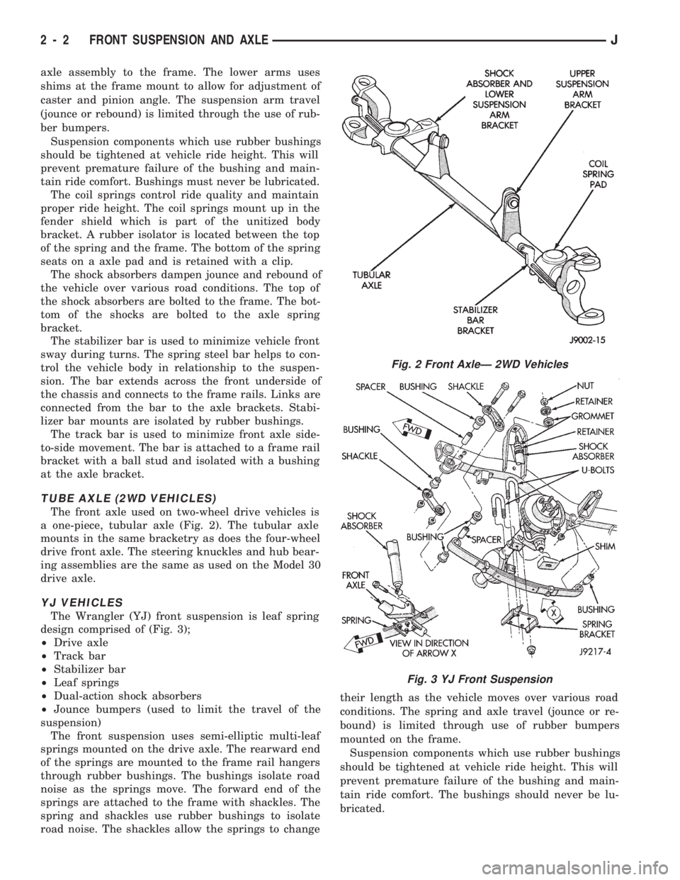
The front axle used on two-wheel drive vehicles is
a one-piece, tubular axle (Fig. 2). The tubular axle
mounts in the same bracketry as does the four-wheel
drive front axle. The steering knuckles and hub bear-
ing assemblies are the same as used on the Model 30
drive axle.
YJ VEHICLES
The Wrangler (YJ) front suspension is leaf spring
design comprised of (Fig. 3);
²Drive axle
²Track bar
²Stabilizer bar
²Leaf springs
²Dual-action shock absorbers
²Jounce bumpers (used to limit the travel of the
suspension)
The front suspension uses semi-elliptic multi-leaf
springs mounted on the drive axle. The rearward end
of the springs are mounted to the frame rail hangers
through rubber bushings. The bushings isolate road
noise as the springs move. The forward end of the
springs are attached to the frame with shackles. The
spring and shackles use rubber bushings to isolate
road noise. The shackles allow the springs to changetheir length as the vehicle moves over various road
conditions. The spring and axle travel (jounce or re-
bound) is limited through use of rubber bumpers
mounted on the frame.
Suspension components which use rubber bushings
should be tightened at vehicle ride height. This will
prevent premature failure of the bushing and main-
tain ride comfort. The bushings should never be lu-
bricated.
Fig. 2 Front AxleÐ 2WD Vehicles
Fig. 3 YJ Front Suspension
2 - 2 FRONT SUSPENSION AND AXLEJ
Page 43 of 1784
not change except when a spindle or ball stud is
damaged or bent. The angle is not adjustable and the
damaged component(s) must be replaced to correct
mis-alignment.
CAUTION:Do not attempt to modify any suspension
or steering component by heating and bending.
PRE-ALIGNMENT INSPECTION
Before starting a front wheel alignment, the follow-
ing inspection and necessary corrections must be
completed.
(1) Tires with the same recommended air pressure,
size, and thread wear. Refer to Group 22, Tires And
Wheels for diagnosis information.
(2) Front wheel bearings for wear.
(3) Ball studs, steering linkage pivot points and
steering gear for looseness, roughness, binding or
wear. Refer to Group 19, Steering for additional in-
formation.
(4) Front wheels for excessive radial or lateral
runout and unbalance. Refer to Group 22, Tires And
Wheels for diagnosis information.
(5) Suspension components for wear and noise.
Check components for correct torque. Refer to Groups
2 and 3, Suspension and Axle for additional informa-
tion.
ALIGNMENT MEASUREMENTS AND ADJUSTMENTS
Before each alignment reading, the vehicle should
be jounced (rear first, then front). Grasp each bumper
at the center and jounce the vehicle up and down
several times. Always release the bumper in the
down position.Set the front end alignment to
specifications with the vehicle at its NOR-
MALLY RIDE HEIGHT.
CAMBER
The wheel camber angle (Fig. 1) is preset at ZERO
DEGREES (0É). The angle is not adjustable and can-
not be altered.
CASTER
The caster angle (Fig. 1) is set at:
²XJ manual transmission, POSITIVE 6.5 DE-
GREES (+6.5É).
²XJ automatic transmission, POSITIVE 8.0 DE-
GREES (+8.0É).
²YJ all transmissions, POSITIVE 6.0 DEGREES
(+6.0É).
Before checking the caster of the front axle for cor-
rect angle. Be sure the axle is not bent or twisted.
Road test the vehicle, and make left and right
turns. If the steering wheel returns to the center po-
sition unassisted, the caster angle is correct. How-ever, if steering wheel does not return toward the
center position unassisted, an incorrect caster angle
is probable.
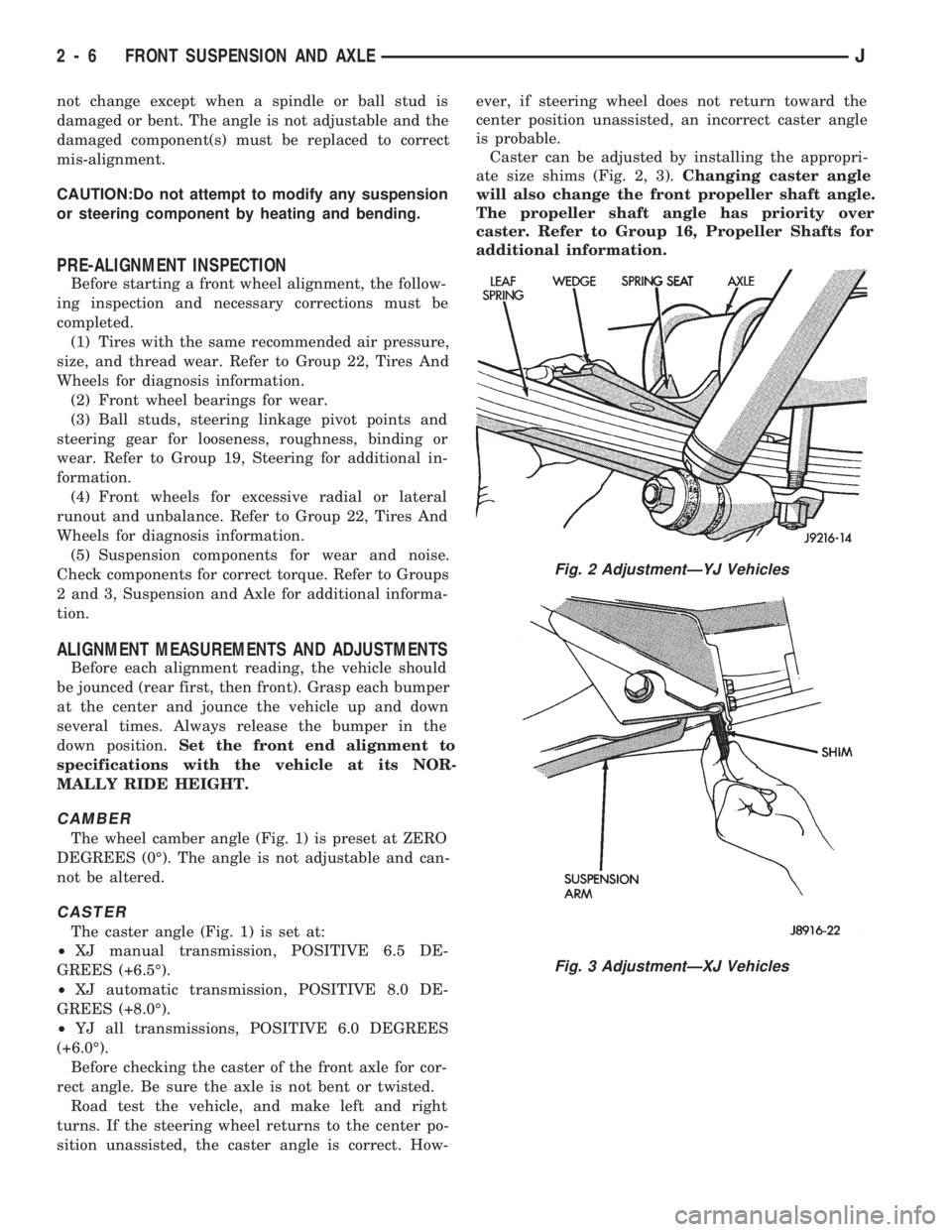
Caster can be adjusted by installing the appropri-
ate size shims (Fig. 2, 3).Changing caster angle
will also change the front propeller shaft angle.
The propeller shaft angle has priority over
caster. Refer to Group 16, Propeller Shafts for
additional information.
Fig. 2 AdjustmentÐYJ Vehicles
Fig. 3 AdjustmentÐXJ Vehicles
2 - 6 FRONT SUSPENSION AND AXLEJ
Page 47 of 1784
XJ FRONT SUSPENSION
INDEX
page page
Axle Bushing Replacement................. 11
Coil Spring............................. 13
Lower Suspension Arm.................... 11
Service Information....................... 10
Shock Absorber.......................... 12Spring and Shock Diagnosis................ 12
Stabilizer Bar............................ 10
Track Bar.............................. 10
Upper Suspension Arm.................... 11
SERVICE INFORMATION
CAUTION: Suspension components that use rubber
bushings should be tightened with the vehicle at
the normal height. It is important to have the
springs supporting the weight of the vehicle when
the fasteners are torqued. If the springs are not at
their normal ride position, vehicle ride comfort
could be affected along with premature bushing
wear. Rubber bushings must never be lubricated.
TRACK BAR
REMOVAL
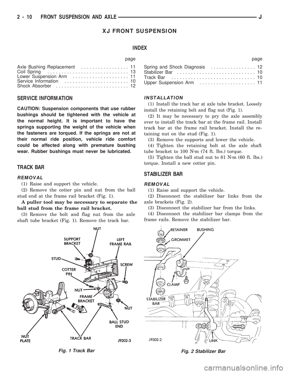
(1) Raise and support the vehicle.
(2) Remove the cotter pin and nut from the ball
stud end at the frame rail bracket (Fig. 1).
A puller tool may be necessary to separate the
ball stud from the frame rail bracket.
(3) Remove the bolt and flag nut from the axle
shaft tube bracket (Fig. 1). Remove the track bar.
INSTALLATION
(1) Install the track bar at axle tube bracket. Loosely
install the retaining bolt and flag nut (Fig. 1).
(2) It may be necessary to pry the axle assembly
over to install the track bar at the frame rail. Install
track bar at the frame rail bracket. Install the re-
taining nut on the stud (Fig. 1).
(3) Remove the supports and lower the vehicle.
(4) Tighten the retaining bolt at the axle shaft
tube bracket to 100 Nzm (74 ft. lbs.) torque.
(5) Tighten the ball stud nut to 81 Nzm (60 ft. lbs.)
torque. Install a new cotter pin.
STABILIZER BAR
REMOVAL
(1) Raise and support the vehicle.
(2) Disconnect the stabilizer bar links from the
axle brackets (Fig. 2).
(3) Disconnect the stabilizer bar from the links.
(4) Disconnect the stabilizer bar clamps from the
frame rails. Remove the stabilizer bar.
Fig. 2 Stabilizer BarFig. 1 Track Bar
2 - 10 FRONT SUSPENSION AND AXLEJ
Page 58 of 1784
Refer to Group 0, Lubrication and Maintenance for
additional information regarding temperature range,
viscosity and fluid level.
CAUTION: If the axle is submerged in water, the lu-
bricant must be replaced immediately to avoid the
possibility of premature axle failure.
DRIVE AXLE ASSEMBLY REPLACEMENTÐXJ
VEHICLES
REMOVAL
(1) Raise the vehicle and position support stands
under the frame rails slightly in behind the lower
suspension arm frame brackets.
(2) Remove the front wheels.
(3) Remove the brake components and ABS brake
sensor (if equipped). Refer to Group 5ÐBrakes.
(4) On 4WD vehicles, disconnect the axle vent
hose.
(5) On 4WD vehicles, mark the drive shaft yoke
and axle pinion yoke for alignment reference. Discon-
nect the drive shaft from the axle.
(6) Disconnect the stabilizer bar link at the axle
bracket.
(7) Disconnect the shock absorbers from axle
bracket.
(8) Disconnect the track bar from the axle bracket.
(9) Disconnect the tie rod and drag link from the
steering knuckle. Disconnect the steering dampener
from the axle bracket.
(10) Support the axle with a hydraulic jack under
the differential.
(11) Disconnect the upper and lower suspension
arms from the axle bracket.
(12) Lower the jack enough to remove the axle.
The coil springs will drop with the axle.
(13) Remove the coil springs from the axle bracket.
INSTALLATION
CAUTION: All suspension components that use rub-
ber bushings should be tightened with the vehicle
at the ride height. It is important to have the
springs supporting the weight of the vehicle when
the fasteners are torqued. If the springs are not at
their normal ride position, vehicle ride comfort
could be affected along with premature rubber
bushing wear. Rubber bushings must never be lu-
bricated.
(1) Install the springs and retainer clip. Tighten
the retainer bolts to 21 Nzm (16 ft. lbs.) torque.
(2) Support the axle on a hydraulic jack under the
differential. Position the axle under the vehicle.
(3) Raise the axle with a floor jack and align it
with the spring pads.(4) Position the upper and lower suspension arm at
the axle bracket. Install bolts and nuts finger
tighten.
(5) Connect the track bar to the axle bracket and
install the bolt.Do not tighten at this time.
It is important that the springs support the
weight of the vehicle when the track bar is con-
nected. If the springs are not at their usual po-
sition, the vehicle ride comfort could be affected.
(6) Install the shock absorber and tighten the bolt
to 19 Nzm (14 ft. lbs.) torque.
(7) Install the stabilizer bar link to the axle
bracket. Tighten the nut to 95 Nzm (70 ft. lbs.)
torque.
(8) Install the drag link and tie rod to the steering
knuckles and tighten the nuts to 47 Nzm (35 ft. lbs.)
torque. Install the steering dampener to the axle
bracket and tighten the nut to 75 Nzm (55 ft. lbs.)
torque.
(9) Install the brake components and ABS brake
sensor (if equipped). Refer to Group 5ÐBrakes.
(10) On 4WD vehicles, connect the vent hose to the
tube fitting.
(11) On 4WD vehicles, align the reference marks
and connect the drive shaft to the axle yoke. Tighten
the U-joint clamp bolts to 19 Nzm (14 ft. lbs.) torque.
(12) Check differential lubricant and add if neces-
sary.
(13) Install the wheel and tire assemblies.
(14) Remove the supports and lower the vehicle.
(15) Tighten the upper suspension arm nuts to 75
Nzm (55 ft. lbs.) torque. Tighten the lower suspension
arm nuts to 115 Nzm (85 ft. lbs.) torque.
(16) Tighten the track bar bolt at the axle bracket
to 100 Nzm (74 ft. lbs.) torque.
(17) Check the front wheel alignment.
DRIVE AXLE ASSEMBLY REPLACEMENTÐYJ
VEHICLES
REMOVAL
(1) Raise the vehicle and position support stands
under the frame rails slightly behind the spring
frame brackets.
(2) Remove the front wheels.
(3) Remove the brake components and ABS brake
sensor (if equipped). Refer to Group 5ÐBrakes.
(4) Disconnect the axle vent hose and axle shift
motor vacuum harness.
(5) Mark the drive shaft yoke and axle pinion yoke
for alignment reference. Disconnect the drive shaft
from the axle.
(6) Disconnect the stabilizer bar link at the axle
bracket.
(7) Disconnect the shock absorbers from axle
bracket.
(8) Disconnect the track bar from the axle bracket.
JFRONT SUSPENSION AND AXLE 2 - 21
Page 59 of 1784
(9) Disconnect the tie rod from the steering
knuckle. Disconnect the steering dampener from the
axle bracket.
(10) Support the axle with a hydraulic jack under
the differential. Raise the axle just enough to relieve
the axle weight from the springs.
(11) Remove the spring U-bolts from the plate
brackets.
(12) Loosen BUT DO NOT REMOVE the bolts that
attach the spring rear pivot at the frame rail brack-
ets. This will allow the springs to pivot without bind-
ing on the bushings.
(13) Disconnect shackle from the springs and lower
the springs to the surface.
(14) Lower the jack enough to remove the axle.
INSTALLATION
CAUTION: All suspension components that use rub-
ber bushings should be tightened with the vehicle
at the normal height. It is important to have the
springs supporting the weight of the vehicle when
the fasteners are torqued. If the springs are not at
their normal ride position, vehicle ride comfort
could be affected along with premature rubber
bushing wear. Rubber bushings must never be lu-
bricated.
(1) Support the axle on a hydraulic jack under the
differential. Position the axle under the vehicle.
(2) Raise the springs and install the spring shackle
bolts.Do not tighten at this time.
(3) Lower the axle and align the spring center
bolts with the locating holes in the axle pads and
plate brackets.
(4) Install the spring U-bolts through the plate
brackets and tighten to 122 Nzm (90 ft. lbs.) torque.
(5) Connect the track bar to the axle bracket and
install the bolt.Do not tighten at this time.
It is important that the springs support the
weight of the vehicle when the track bar is con-
nected. If the springs are not at their usual po-
sition, the vehicle ride comfort could be affected.
(6) Install the shock absorber and tighten the nut
to 61 Nzm (45 ft. lbs.) torque.
(7) Install the stabilizer bar link to the axle
bracket. Tighten the nut to 61 Nzm (45 ft. lbs.)
torque.
(8) Install the tie rod to the steering knuckles and
tighten the nuts to 47 Nzm (35 ft. lbs.) torque. Install
the steering dampener to the axle bracket and
tighten the bolt to 75 Nzm (55 ft. lbs.) torque.
(9) Install the brake components and ABS brake
sensor (if equipped). Refer to Group 5ÐBrakes.
(10) Connect the vent hose to the tube fitting and
axle shift motor vacuum harness.(11) Align the reference marks and connect the
drive shaft to the axle yoke. Tighten the U-joint
clamp bolts to 19 Nzm (14 ft. lbs.) torque.
(12) Check differential lubricant and add if neces-
sary.
(13) Install the wheel and tire assemblies.
(14) Remove the supports and lower the vehicle.
(15) Tighten the spring rear pivot bolt/nut to 142
Nzm (105 ft. lbs.) torque. Tighten the spring shackle
bolt/nut to 135 Nzm (100 ft. lbs.) torque.
(16) Tighten the track bar nut at the axle bracket
to 100 Nzm (74 ft. lbs.) torque.
(17) Check the front wheel alignment.
LUBRICANT CHANGE
The gear lubricant will drain quicker if the vehicle
has been recently driven.
(1) Raise and support the vehicle.
(2) Remove the lubricant fill hole plug from the
differential housing cover.
(3) Remove the differential housing cover and
drain the lubricant from the housing.
(4) Clean the housing cavity with a flushing oil,
light engine oil or lint free cloth.Do not use water,
steam, kerosene or gasoline for cleaning.
(5) Remove the sealant from the housing and cover
surfaces. Use solvent to clean the mating surfaces.
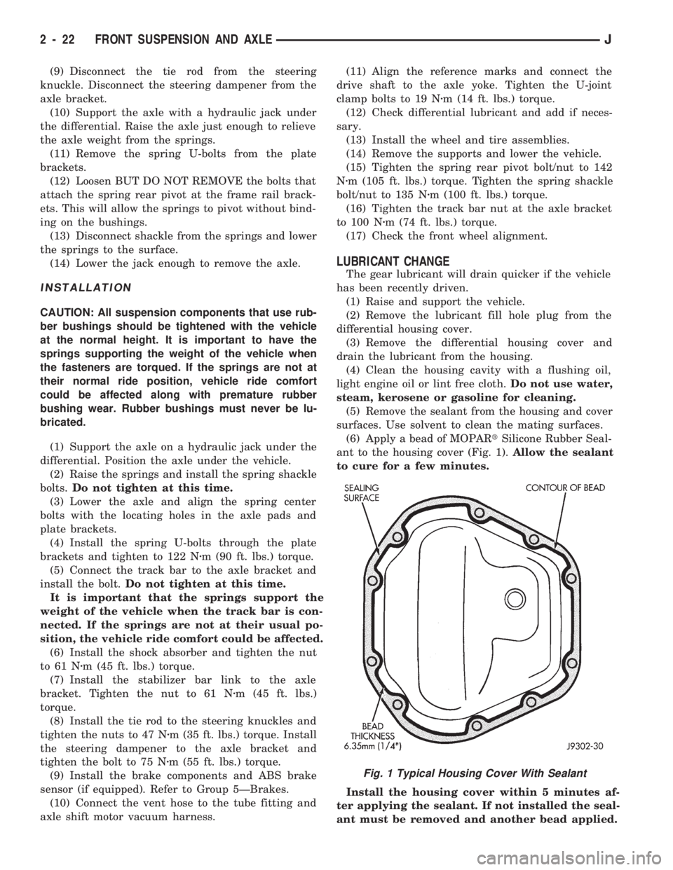
(6) Apply a bead of MOPARtSilicone Rubber Seal-
ant to the housing cover (Fig. 1).Allow the sealant
to cure for a few minutes.
Install the housing cover within 5 minutes af-
ter applying the sealant. If not installed the seal-
ant must be removed and another bead applied.
Fig. 1 Typical Housing Cover With Sealant
2 - 22 FRONT SUSPENSION AND AXLEJ
Page 76 of 1784
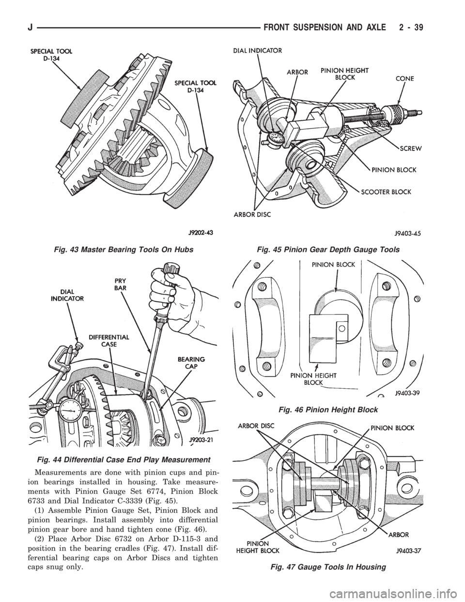
Measurements are done with pinion cups and pin-
ion bearings installed in housing. Take measure-
ments with Pinion Gauge Set 6774, Pinion Block
6733 and Dial Indicator C-3339 (Fig. 45).
(1) Assemble Pinion Gauge Set, Pinion Block and
pinion bearings. Install assembly into differential
pinion gear bore and hand tighten cone (Fig. 46).
(2) Place Arbor Disc 6732 on Arbor D-115-3 and
position in the bearing cradles (Fig. 47). Install dif-
ferential bearing caps on Arbor Discs and tighten
caps snug only.
Fig. 45 Pinion Gear Depth Gauge Tools
Fig. 46 Pinion Height Block
Fig. 47 Gauge Tools In Housing
Fig. 43 Master Bearing Tools On Hubs
Fig. 44 Differential Case End Play Measurement
JFRONT SUSPENSION AND AXLE 2 - 39
Page 77 of 1784
Arbor Discs have different steps to fit other
axle sizes. Pick correct size step for axle being
serviced.
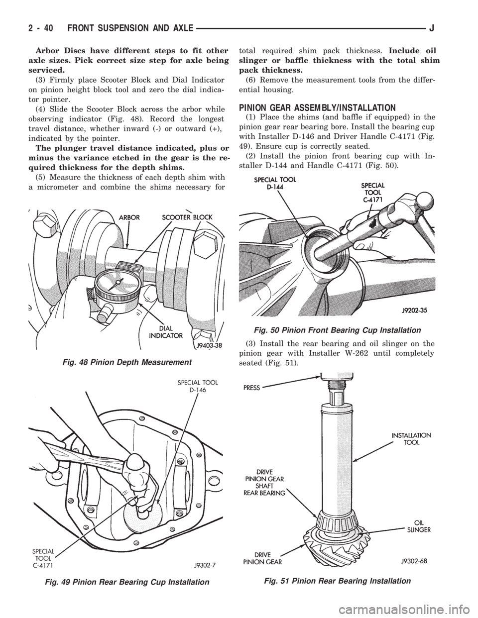
(3) Firmly place Scooter Block and Dial Indicator
on pinion height block tool and zero the dial indica-
tor pointer.
(4) Slide the Scooter Block across the arbor while
observing indicator (Fig. 48). Record the longest
travel distance, whether inward (-) or outward (+),
indicated by the pointer.
The plunger travel distance indicated, plus or
minus the variance etched in the gear is the re-
quired thickness for the depth shims.
(5) Measure the thickness of each depth shim with
a micrometer and combine the shims necessary fortotal required shim pack thickness.Include oil
slinger or baffle thickness with the total shim
pack thickness.
(6) Remove the measurement tools from the differ-
ential housing.
PINION GEAR ASSEMBLY/INSTALLATION
(1) Place the shims (and baffle if equipped) in the
pinion gear rear bearing bore. Install the bearing cup
with Installer D-146 and Driver Handle C-4171 (Fig.
49). Ensure cup is correctly seated.
(2) Install the pinion front bearing cup with In-
staller D-144 and Handle C-4171 (Fig. 50).
(3) Install the rear bearing and oil slinger on the
pinion gear with Installer W-262 until completely
seated (Fig. 51).
Fig. 48 Pinion Depth Measurement
Fig. 49 Pinion Rear Bearing Cup Installation
Fig. 50 Pinion Front Bearing Cup Installation
Fig. 51 Pinion Rear Bearing Installation
2 - 40 FRONT SUSPENSION AND AXLEJ