1994 JEEP CHEROKEE height
[x] Cancel search: heightPage 1338 of 1784
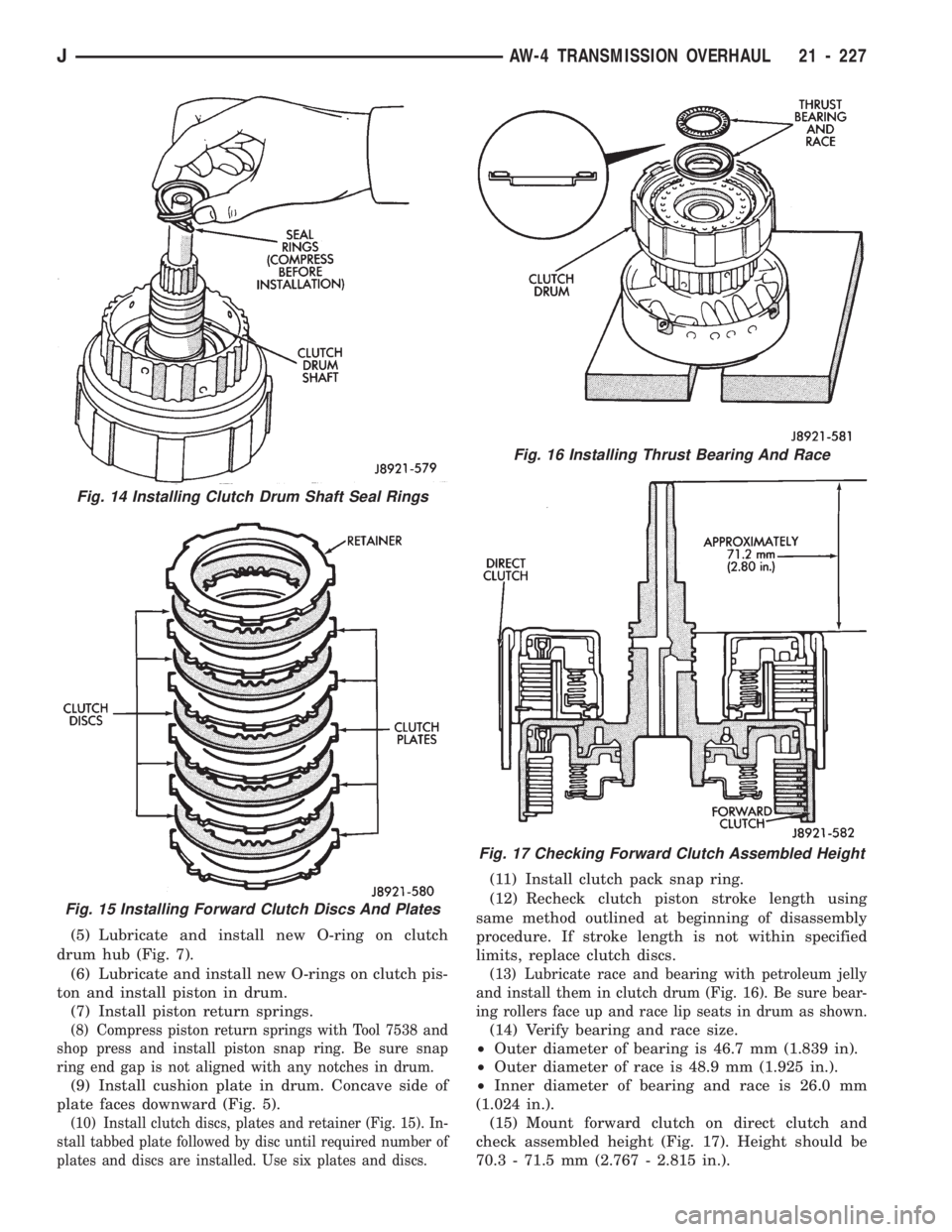
(5) Lubricate and install new O-ring on clutch
drum hub (Fig. 7).
(6) Lubricate and install new O-rings on clutch pis-
ton and install piston in drum.
(7) Install piston return springs.
(8) Compress piston return springs with Tool 7538 and
shop press and install piston snap ring. Be sure snap
ring end gap is not aligned with any notches in drum.
(9) Install cushion plate in drum. Concave side of
plate faces downward (Fig. 5).
(10) Install clutch discs, plates and retainer (Fig. 15). In-
stall tabbed plate followed by disc until required number of
plates and discs are installed. Use six plates and discs.
(11) Install clutch pack snap ring.
(12) Recheck clutch piston stroke length using
same method outlined at beginning of disassembly
procedure. If stroke length is not within specified
limits, replace clutch discs.
(13) Lubricate race and bearing with petroleum jelly
and install them in clutch drum (Fig. 16). Be sure bear-
ing rollers face up and race lip seats in drum as shown.
(14) Verify bearing and race size.
²Outer diameter of bearing is 46.7 mm (1.839 in).
²Outer diameter of race is 48.9 mm (1.925 in.).
²Inner diameter of bearing and race is 26.0 mm
(1.024 in.).
(15) Mount forward clutch on direct clutch and
check assembled height (Fig. 17). Height should be
70.3 - 71.5 mm (2.767 - 2.815 in.).
Fig. 15 Installing Forward Clutch Discs And Plates
Fig. 16 Installing Thrust Bearing And Race
Fig. 17 Checking Forward Clutch Assembled Height
Fig. 14 Installing Clutch Drum Shaft Seal Rings
JAW-4 TRANSMISSION OVERHAUL 21 - 227
Page 1464 of 1784
(6) Attach the latch release cable to the clips.
(7) Connect the latches to the latch rod and posi-
tion them on the hood.
(8) Install the screws to attach the latches to the
hood.
Tighten the screws to 9 Nzm (77 in-lbs) torque.
(9) Position the safety latch on the hood and install
the attaching nuts. Tighten the screws to 13 Nzm
(115 in-lbs) torque.
(10) Test latch release cable and latches for proper
operation.
(11) Connect the underhood lamp wire harness
connector.
(12) Inspect the hood for proper alignment and ad-
just as necessary.
HOOD ADJUSTMENT
The hood bolt holes are elongated for fore and aft
and side-to-side adjustment.
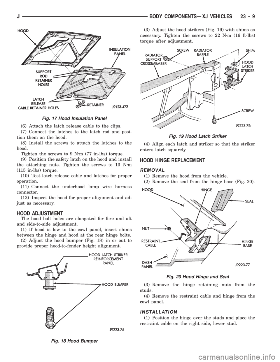
(1) If hood is low to the cowl panel, insert shims
between the hinge and hood at the rear hinge bolts.
(2) Adjust the hood bumper (Fig. 18) in or out to
provide proper hood-to-fender height alignment.(3) Adjust the hood strikers (Fig. 19) with shims as
necessary. Tighten the screws to 22 Nzm (16 ft-lbs)
torque after adjustment.
(4) Align each latch and striker so that the striker
enters latch squarely.
HOOD HINGE REPLACEMENT
REMOVAL
(1) Remove the hood from the vehicle.
(2) Remove the seal from the hinge base (Fig. 20).
(3) Remove the hinge retaining nuts from the
studs.
(4) Remove the restraint cable and hinge from the
cowl panel.
INSTALLATION
(1) Position the hinge over the studs and place the
restraint cable on the right side, lower stud.
Fig. 17 Hood Insulation Panel
Fig. 18 Hood Bumper
Fig. 19 Hood Latch Striker
Fig. 20 Hood Hinge and Seal
JBODY COMPONENTSÐXJ VEHICLES 23 - 9
Page 1603 of 1784
FRONT FASCIA AND SKID PLATEÐYJ RENEGADE
VEHICLES
The skid plate and the front fascia can also be
removed independently.
REMOVAL
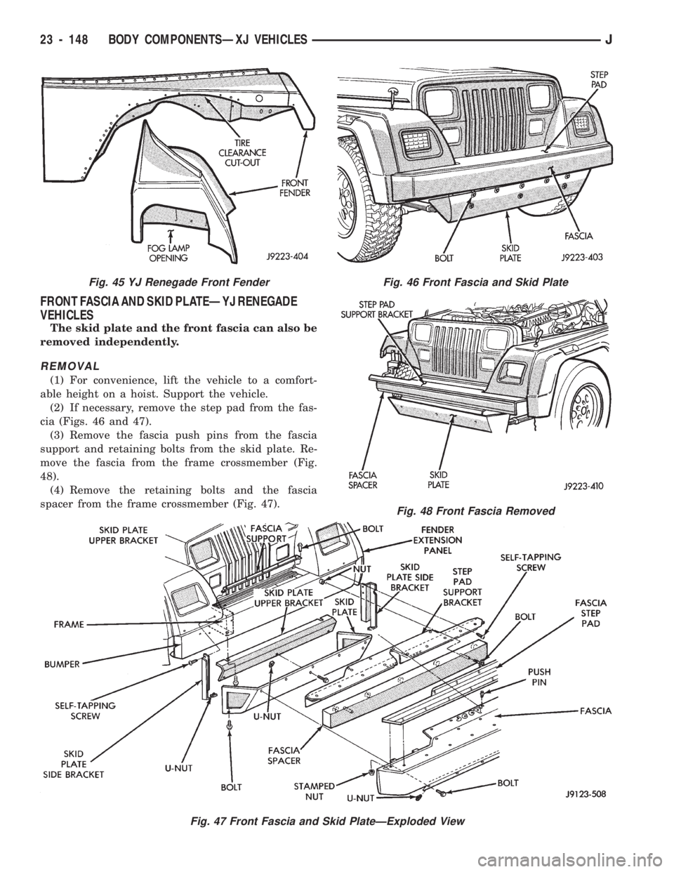
(1) For convenience, lift the vehicle to a comfort-
able height on a hoist. Support the vehicle.
(2) If necessary, remove the step pad from the fas-
cia (Figs. 46 and 47).
(3) Remove the fascia push pins from the fascia
support and retaining bolts from the skid plate. Re-
move the fascia from the frame crossmember (Fig.
48).
(4) Remove the retaining bolts and the fascia
spacer from the frame crossmember (Fig. 47).
Fig. 46 Front Fascia and Skid Plate
Fig. 47 Front Fascia and Skid PlateÐExploded View
Fig. 48 Front Fascia Removed
Fig. 45 YJ Renegade Front Fender
23 - 148 BODY COMPONENTSÐXJ VEHICLESJ
Page 1604 of 1784
(5) Remove the retaining screws and the fascia
step pad support bracket from the frame crossmem-
ber (Fig. 47).
(6) Remove the retaining bolts from the skid plate.
Remove the skid plate from the brackets.
(7) Remove the retaining screws from the skid
plate brackets. Remove the brackets from the frame
rails.
(8) Remove the retaining bolts and the fascia sup-
port from the cover plate.
INSTALLATION
(1) Position the fascia support on the cover plate
and install the retaining bolts (Fig. 47). Tighten the
bolts to 5 Nzm (44 in-lbs) torque.
(2) Position the skid plate brackets at the frame
rails and install the retaining screws. Tighten the
screws to 25 Nzm (18 ft-lbs) torque.
(3) Position the skid plate at the brackets and in-
stall the retaining bolts. Tighten the bolts to 25 Nzm
(18 ft-lbs) torque.
(4) Position the fascia step pad support bracket at
the frame crossmember and install the retaining
screws. Tighten the screws to 25 Nzm (18 ft-lbs)
torque.
(5) Position the fascia spacer at the frame cross-
member and install the retaining bolts. Tighten the
nuts to 6 Nzm (53 in-lbs) torque.
(6) Position the fascia at the frame crossmember
and install the retaining bolts and push pins.
Tighten the bolts to 10 Nzm (7 ft-lbs) torque.
(7) Install the step pad on the fascia.
(8) If applicable, remove the support and lower the
vehicle.
FRONT FENDER EXTENSION PANELÐYJ RENEGADE
VEHICLES
REMOVAL
(1) For convenience, lift the vehicle to a comfort-
able height on a hoist. Support the vehicle.
(2) Remove the radio antenna mast from the
fender extension panel.
(3) Remove the hood bumper from the extension
panel.
(4) Remove the fog lamp from the extension panel.
If necessary, refer to the removal procedure.
(5) Detach the hood latch from the hood.
(6) Disconnect the side marker lamp wire harness
bulb socket.
(7) Remove the push pins that attach the fender
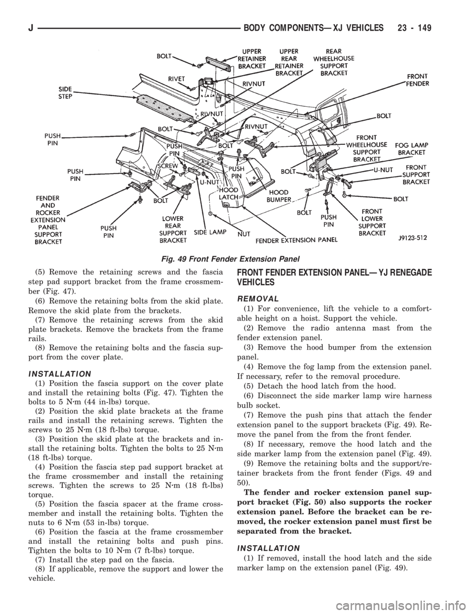
extension panel to the support brackets (Fig. 49). Re-
move the panel from the from the front fender.
(8) If necessary, remove the hood latch and the
side marker lamp from the extension panel (Fig. 49).
(9) Remove the retaining bolts and the support/re-
tainer brackets from the front fender (Figs. 49 and
50).
The fender and rocker extension panel sup-
port bracket (Fig. 50) also supports the rocker
extension panel. Before the bracket can be re-
moved, the rocker extension panel must first be
separated from the bracket.
INSTALLATION
(1) If removed, install the hood latch and the side
marker lamp on the extension panel (Fig. 49).
Fig. 49 Front Fender Extension Panel
JBODY COMPONENTSÐXJ VEHICLES 23 - 149
Page 1605 of 1784
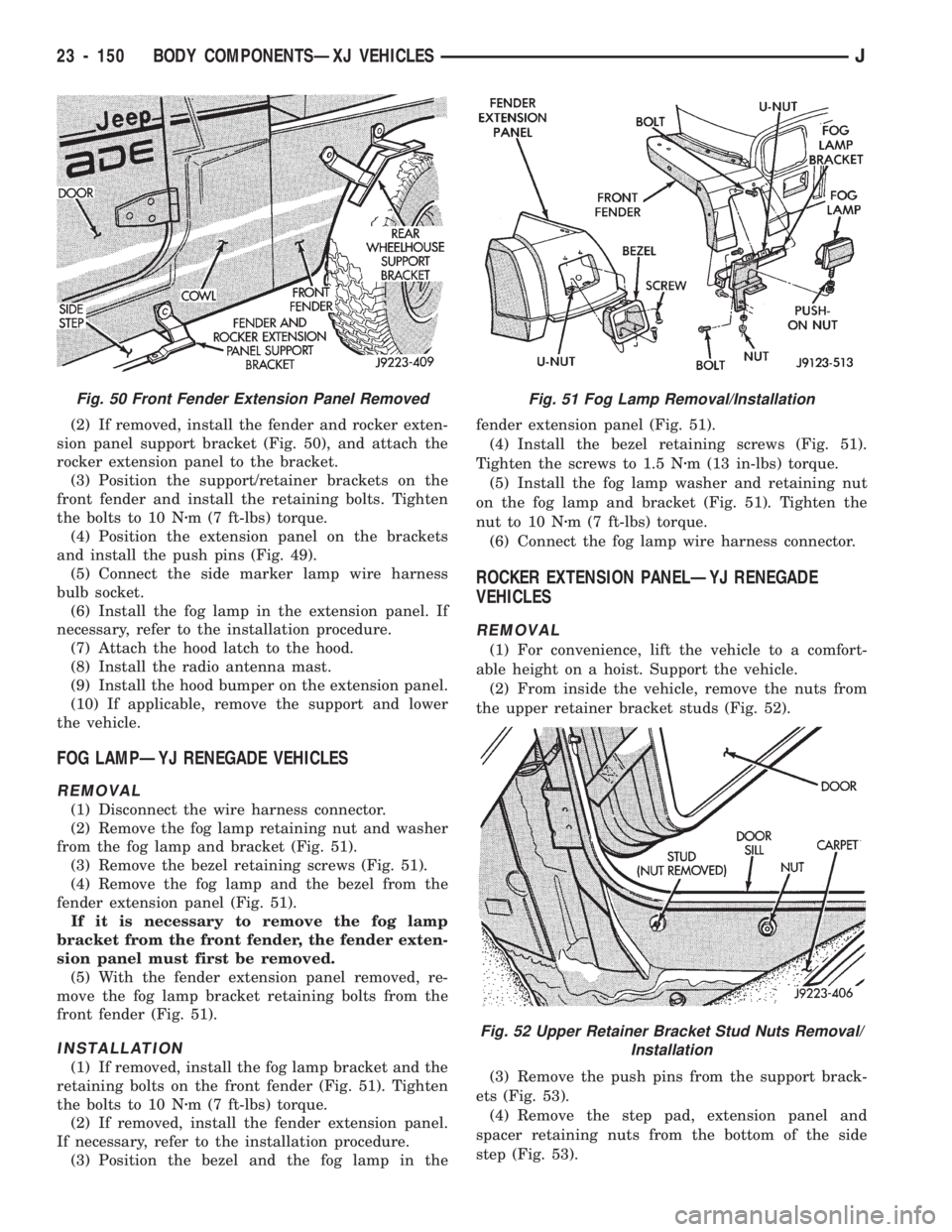
(2) If removed, install the fender and rocker exten-
sion panel support bracket (Fig. 50), and attach the
rocker extension panel to the bracket.
(3) Position the support/retainer brackets on the
front fender and install the retaining bolts. Tighten
the bolts to 10 Nzm (7 ft-lbs) torque.
(4) Position the extension panel on the brackets
and install the push pins (Fig. 49).
(5) Connect the side marker lamp wire harness
bulb socket.
(6) Install the fog lamp in the extension panel. If
necessary, refer to the installation procedure.
(7) Attach the hood latch to the hood.
(8) Install the radio antenna mast.
(9) Install the hood bumper on the extension panel.
(10) If applicable, remove the support and lower
the vehicle.
FOG LAMPÐYJ RENEGADE VEHICLES
REMOVAL
(1) Disconnect the wire harness connector.
(2) Remove the fog lamp retaining nut and washer
from the fog lamp and bracket (Fig. 51).
(3) Remove the bezel retaining screws (Fig. 51).
(4) Remove the fog lamp and the bezel from the
fender extension panel (Fig. 51).
If it is necessary to remove the fog lamp
bracket from the front fender, the fender exten-
sion panel must first be removed.
(5) With the fender extension panel removed, re-
move the fog lamp bracket retaining bolts from the
front fender (Fig. 51).
INSTALLATION
(1) If removed, install the fog lamp bracket and the
retaining bolts on the front fender (Fig. 51). Tighten
the bolts to 10 Nzm (7 ft-lbs) torque.
(2) If removed, install the fender extension panel.
If necessary, refer to the installation procedure.
(3) Position the bezel and the fog lamp in thefender extension panel (Fig. 51).
(4) Install the bezel retaining screws (Fig. 51).
Tighten the screws to 1.5 Nzm (13 in-lbs) torque.
(5) Install the fog lamp washer and retaining nut
on the fog lamp and bracket (Fig. 51). Tighten the
nut to 10 Nzm (7 ft-lbs) torque.
(6) Connect the fog lamp wire harness connector.
ROCKER EXTENSION PANELÐYJ RENEGADE
VEHICLES
REMOVAL
(1) For convenience, lift the vehicle to a comfort-
able height on a hoist. Support the vehicle.
(2) From inside the vehicle, remove the nuts from
the upper retainer bracket studs (Fig. 52).
(3) Remove the push pins from the support brack-
ets (Fig. 53).
(4) Remove the step pad, extension panel and
spacer retaining nuts from the bottom of the side
step (Fig. 53).
Fig. 50 Front Fender Extension Panel RemovedFig. 51 Fog Lamp Removal/Installation
Fig. 52 Upper Retainer Bracket Stud Nuts Removal/
Installation
23 - 150 BODY COMPONENTSÐXJ VEHICLESJ
Page 1606 of 1784
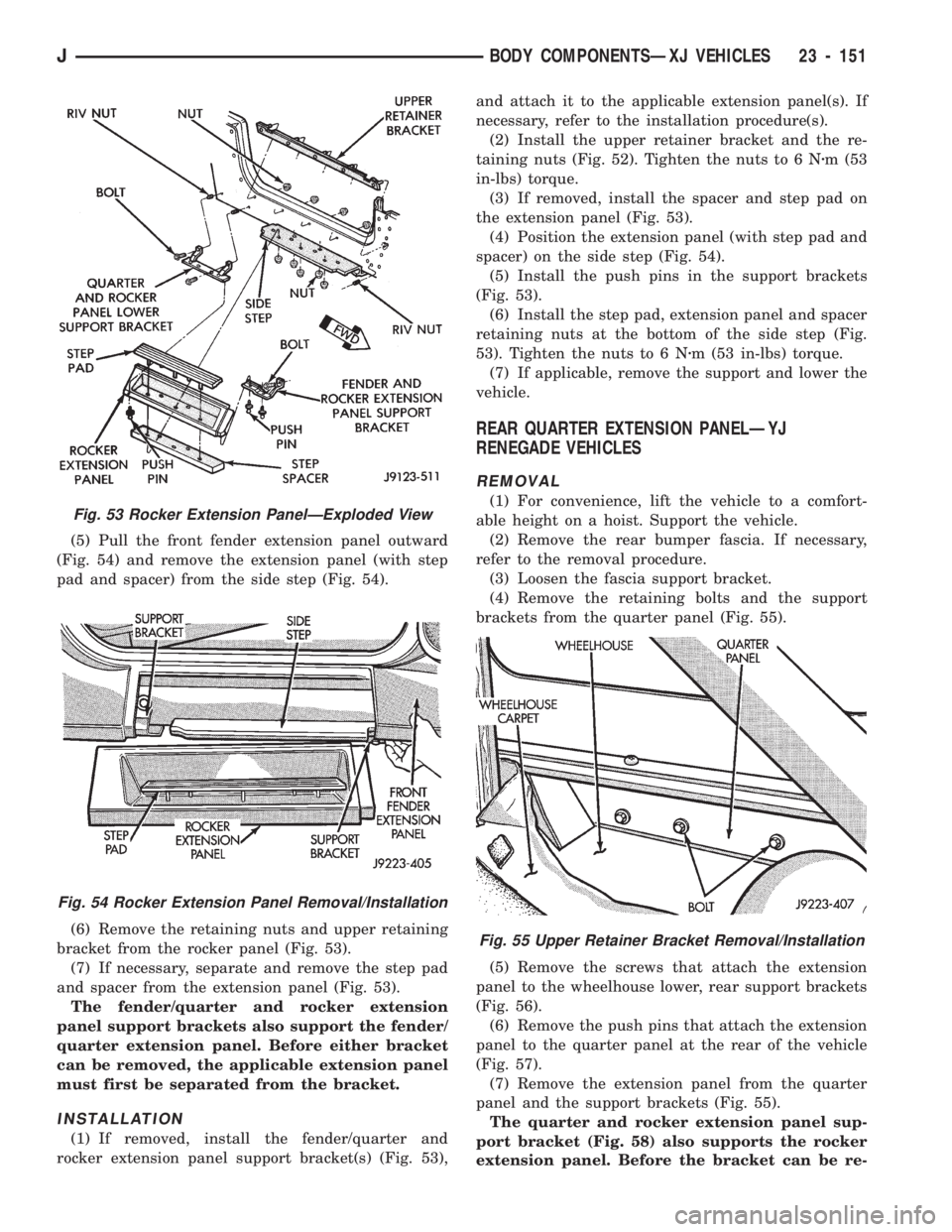
(5) Pull the front fender extension panel outward
(Fig. 54) and remove the extension panel (with step
pad and spacer) from the side step (Fig. 54).
(6) Remove the retaining nuts and upper retaining
bracket from the rocker panel (Fig. 53).
(7) If necessary, separate and remove the step pad
and spacer from the extension panel (Fig. 53).
The fender/quarter and rocker extension
panel support brackets also support the fender/
quarter extension panel. Before either bracket
can be removed, the applicable extension panel
must first be separated from the bracket.
INSTALLATION
(1) If removed, install the fender/quarter and
rocker extension panel support bracket(s) (Fig. 53),and attach it to the applicable extension panel(s). If
necessary, refer to the installation procedure(s).
(2) Install the upper retainer bracket and the re-
taining nuts (Fig. 52). Tighten the nuts to 6 Nzm (53
in-lbs) torque.
(3) If removed, install the spacer and step pad on
the extension panel (Fig. 53).
(4) Position the extension panel (with step pad and
spacer) on the side step (Fig. 54).
(5) Install the push pins in the support brackets
(Fig. 53).
(6) Install the step pad, extension panel and spacer
retaining nuts at the bottom of the side step (Fig.
53). Tighten the nuts to 6 Nzm (53 in-lbs) torque.
(7) If applicable, remove the support and lower the
vehicle.
REAR QUARTER EXTENSION PANELÐYJ
RENEGADE VEHICLES
REMOVAL
(1) For convenience, lift the vehicle to a comfort-
able height on a hoist. Support the vehicle.
(2) Remove the rear bumper fascia. If necessary,
refer to the removal procedure.
(3) Loosen the fascia support bracket.
(4) Remove the retaining bolts and the support
brackets from the quarter panel (Fig. 55).
(5) Remove the screws that attach the extension
panel to the wheelhouse lower, rear support brackets
(Fig. 56).
(6) Remove the push pins that attach the extension
panel to the quarter panel at the rear of the vehicle
(Fig. 57).
(7) Remove the extension panel from the quarter
panel and the support brackets (Fig. 55).
The quarter and rocker extension panel sup-
port bracket (Fig. 58) also supports the rocker
extension panel. Before the bracket can be re-
Fig. 55 Upper Retainer Bracket Removal/Installation
Fig. 53 Rocker Extension PanelÐExploded View
Fig. 54 Rocker Extension Panel Removal/Installation
JBODY COMPONENTSÐXJ VEHICLES 23 - 151
Page 1607 of 1784
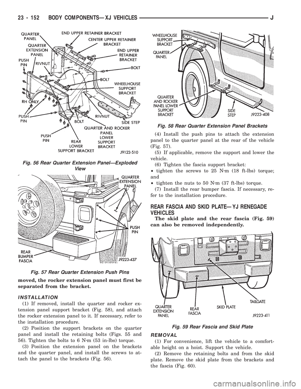
moved, the rocker extension panel must first be
separated from the bracket.
INSTALLATION
(1) If removed, install the quarter and rocker ex-
tension panel support bracket (Fig. 58), and attach
the rocker extension panel to it. If necessary, refer to
the installation procedure.
(2) Position the support brackets on the quarter
panel and install the retaining bolts (Figs. 55 and
56). Tighten the bolts to 6 Nzm (53 in-lbs) torque.
(3) Position the extension panel on the brackets
and the quarter panel, and install the screws to at-
tach the panel to the brackets (Fig. 56).(4) Install the push pins to attach the extension
panel to the quarter panel at the rear of the vehicle
(Fig. 57).
(5) If applicable, remove the support and lower the
vehicle.
(6) Tighten the fascia support bracket:
²tighten the screws to 25 Nzm (18 ft-lbs) torque;
and
²tighten the nuts to 50 Nzm (37 ft-lbs) torque.
(7) Install the rear bumper fascia. If necessary, re-
fer to the installation procedure.
REAR FASCIA AND SKID PLATEÐYJ RENEGADE
VEHICLES
The skid plate and the rear fascia (Fig. 59)
can also be removed independently.
REMOVAL
(1) For convenience, lift the vehicle to a comfort-
able height on a hoist. Support the vehicle.
(2) Remove the retaining bolts and from the skid
plate. Remove the skid plate from the brackets and
the fascia (Fig. 60).
Fig. 56 Rear Quarter Extension PanelÐExploded
View
Fig. 57 Rear Quarter Extension Push Pins
Fig. 58 Rear Quarter Extension Panel Brackets
Fig. 59 Rear Fascia and Skid Plate
23 - 152 BODY COMPONENTSÐXJ VEHICLESJ