1994 JEEP CHEROKEE chains
[x] Cancel search: chainsPage 10 of 1784
²if the vehicle is damaged, secure the loose and pro-
truding parts;
²always use a safety chain system that is indepen-
dent of the lifting and towing equipment;
²do not allow any of the towing equipment to con-
tact the disabled vehicle's fuel tank;
²do not allow anyone to be under the disabled vehi-
cle while it is lifted by the towing equipment;
²do not allow passengers to ride in a vehicle being
towed;
²always observe all state and local laws involving
warning signals, night illumination, speed, etc.
²do not attempt a towing operation that could jeop-
ardize the safety of the operator, bystanders or other
motorists;
²do not exceed a towing speed of 48 km/h (30 mph);
²avoid towing distances of more than 24 km (15
miles) whenever possible; and
²do not attach tow chains or a tow sling to a
bumper, the steering linkage, the universal joints,
the constant velocity (CV) joints, or a drive shaft.
CLEARANCES AND RAMP ANGLE
SURFACE CLEARANCE
The end of the disabled vehicle that is attached to
the tow vehicle should be lifted a minimum of 10 cm
or four inches off the surface. Inspect to ensure that
the opposite end of the disabled vehicle has clearance
from the surface.
RAMP ANGLEÐFLAT-BED TOWING
If a vehicle with flat-bed towing equipment is used,
the approach ramp angle should not exceed 15 de-
grees.
SLING-TYPE, FRONT-END TOWING
XJ VEHICLES
Use the following guidelines when the tow vehicle
is attached to the front end of a disabled vehicle.
(1) Always tow with the front wheels lifted off the
surface and turned all the way to the right.
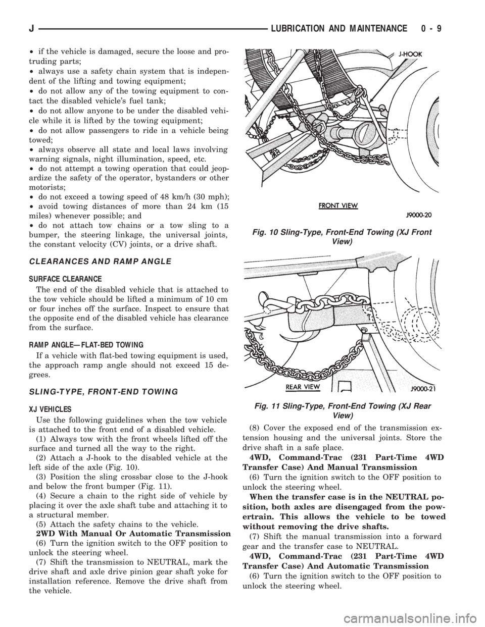
(2) Attach a J-hook to the disabled vehicle at the
left side of the axle (Fig. 10).
(3) Position the sling crossbar close to the J-hook
and below the front bumper (Fig. 11).
(4) Secure a chain to the right side of vehicle by
placing it over the axle shaft tube and attaching it to
a structural member.
(5) Attach the safety chains to the vehicle.
2WD With Manual Or Automatic Transmission
(6) Turn the ignition switch to the OFF position to
unlock the steering wheel.
(7) Shift the transmission to NEUTRAL, mark the
drive shaft and axle drive pinion gear shaft yoke for
installation reference. Remove the drive shaft from
the vehicle.(8) Cover the exposed end of the transmission ex-
tension housing and the universal joints. Store the
drive shaft in a safe place.
4WD, Command-Trac (231 Part-Time 4WD
Transfer Case) And Manual Transmission
(6) Turn the ignition switch to the OFF position to
unlock the steering wheel.
When the transfer case is in the NEUTRAL po-
sition, both axles are disengaged from the pow-
ertrain. This allows the vehicle to be towed
without removing the drive shafts.
(7) Shift the manual transmission into a forward
gear and the transfer case to NEUTRAL.
4WD, Command-Trac (231 Part-Time 4WD
Transfer Case) And Automatic Transmission
(6) Turn the ignition switch to the OFF position to
unlock the steering wheel.
Fig. 10 Sling-Type, Front-End Towing (XJ Front
View)
Fig. 11 Sling-Type, Front-End Towing (XJ Rear
View)
JLUBRICATION AND MAINTENANCE 0 - 9
Page 11 of 1784
When the transfer case is in the NEUTRAL po-
sition, both axles are disengaged from the pow-
ertrain. This allows the vehicle to be towed
without removing the drive shafts.
(7) Shift the automatic transmission to PARK and
the transfer case to NEUTRAL.
4WD, Selec-Trac (242 Full-Time 4WD Transfer
Case) And Automatic Transmission
(6) Turn the ignition switch to the OFF position to
unlock the steering wheel.
When the transfer case is in the NEUTRAL po-
sition, both axles are disengaged from the pow-
ertrain. This allows the vehicle to be towed
without removing the drive shafts.
(7) Shift the automatic transmission to PARK and
the transfer case to NEUTRAL.
YJ VEHICLES
Use the following guidelines when the tow vehicle
is attached to the front of a disabled vehicle.
(1) Always tow with the front wheels lifted off the
surface and turned all the way to the right.
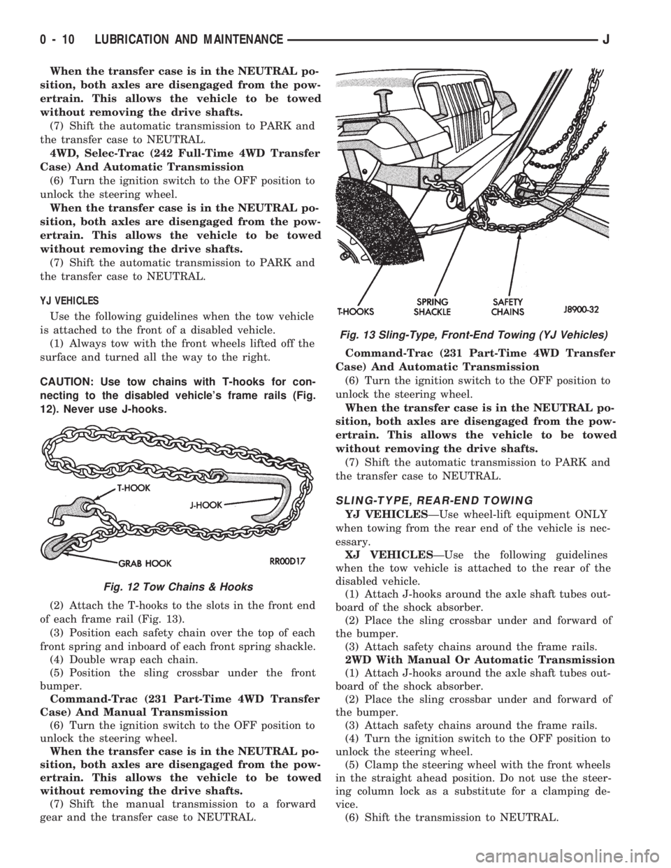
CAUTION: Use tow chains with T-hooks for con-
necting to the disabled vehicle's frame rails (Fig.
12). Never use J-hooks.
(2) Attach the T-hooks to the slots in the front end
of each frame rail (Fig. 13).
(3) Position each safety chain over the top of each
front spring and inboard of each front spring shackle.
(4) Double wrap each chain.
(5) Position the sling crossbar under the front
bumper.
Command-Trac (231 Part-Time 4WD Transfer
Case) And Manual Transmission
(6) Turn the ignition switch to the OFF position to
unlock the steering wheel.
When the transfer case is in the NEUTRAL po-
sition, both axles are disengaged from the pow-
ertrain. This allows the vehicle to be towed
without removing the drive shafts.
(7) Shift the manual transmission to a forward
gear and the transfer case to NEUTRAL.Command-Trac (231 Part-Time 4WD Transfer
Case) And Automatic Transmission
(6) Turn the ignition switch to the OFF position to
unlock the steering wheel.
When the transfer case is in the NEUTRAL po-
sition, both axles are disengaged from the pow-
ertrain. This allows the vehicle to be towed
without removing the drive shafts.
(7) Shift the automatic transmission to PARK and
the transfer case to NEUTRAL.
SLING-TYPE, REAR-END TOWING
YJ VEHICLESÐUse wheel-lift equipment ONLY
when towing from the rear end of the vehicle is nec-
essary.
XJ VEHICLESÐUse the following guidelines
when the tow vehicle is attached to the rear of the
disabled vehicle.
(1) Attach J-hooks around the axle shaft tubes out-
board of the shock absorber.
(2) Place the sling crossbar under and forward of
the bumper.
(3) Attach safety chains around the frame rails.
2WD With Manual Or Automatic Transmission
(1) Attach J-hooks around the axle shaft tubes out-
board of the shock absorber.
(2) Place the sling crossbar under and forward of
the bumper.
(3) Attach safety chains around the frame rails.
(4) Turn the ignition switch to the OFF position to
unlock the steering wheel.
(5) Clamp the steering wheel with the front wheels
in the straight ahead position. Do not use the steer-
ing column lock as a substitute for a clamping de-
vice.
(6) Shift the transmission to NEUTRAL.
Fig. 12 Tow Chains & Hooks
Fig. 13 Sling-Type, Front-End Towing (YJ Vehicles)
0 - 10 LUBRICATION AND MAINTENANCEJ
Page 12 of 1784
4WD, Command-Trac (231 Part-Time 4WD
Transfer Case) And Manual Transmission
(1) Attach J-hooks around the axle shaft tubes out-
board of the shock absorber.
(2) Place the sling crossbar under and forward of
the bumper.
(3) Attach safety chains around the frame rails.
(4) Turn the ignition switch to the OFF position to
unlock the steering column.
(5) Clamp the steering wheel with the front wheels
in the straight ahead position. Do not use the steer-
ing column lock as a substitute for a clamping de-
vice.
When the transfer case is in the NEUTRAL po-
sition, both axles are disengaged from the pow-
ertrain. This allows the vehicle to be towed
without removing the drive shafts.
(6) Shift the transmission to a forward gear and
the transfer case to NEUTRAL.
4WD, Command-Trac (231 Part-Time 4WD
Transfer Case) And Automatic Transmission
(1) Attach J-hooks around the axle shaft tubes out-
board of the shock absorber.
(2) Place the sling crossbar under and forward of
the bumper.
(3) Attach safety chains around the frame rails.
(4) Turn the ignition switch to the OFF position to
unlock the steering column.
(5) Clamp the steering wheel with the front wheels
in the straight ahead position. Do not use the steer-
ing column lock as a substitute for a clamping de-
vice.
When the transfer case is in the NEUTRAL po-
sition, both axles are disengaged from the pow-
ertrain. This allows the vehicle to be towed
without removing the drive shafts.
(6) Shift the transmission to PARK and the trans-
fer case to NEUTRAL.
4WD, Selec-Trac (242 Full-Time 4WD Transfer
Case) And Automatic Transmission
(1) Attach J-hooks around the axle shaft tubes out-
board of the shock absorber.
(2) Place the sling crossbar under and forward of
the bumper.
(3) Attach safety chains around the frame rails.
(4) Turn the ignition switch to the OFF position to
unlock the steering column.
(5) Clamp the steering wheel with the front wheels
in the straight ahead position. Do not use the steer-
ing column lock as a substitute for a clamping de-
vice.
When the transfer case is in the NEUTRAL po-
sition, both axles are disengaged from the pow-
ertrain. This allows the vehicle to be towed
without removing the drive shafts.
(6) Shift the transmission to PARK and the trans-
fer case to NEUTRAL.TOWING WHEN IGNITION KEYS ARE NOT
AVAILABLE
VEHICLE DOORS UNLOCKED
2WD Vehicles
Either one of two methods can be used:
²tow the vehicle with the drive shaft removed (refer
to Sling-Type, Front-End Towing); or
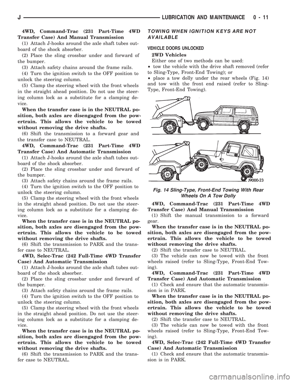
²place a tow dolly under the rear wheels (Fig. 14)
and tow with the front end raised (refer to Sling-
Type, Front-End Towing).
4WD, Command-Trac (231 Part-Time 4WD
Transfer Case) And Manual Transmission
(1) Shift the manual transmission to a forward
gear.
When the transfer case is in the NEUTRAL po-
sition, both axles are disengaged from the pow-
ertrain. This allows the vehicle to be towed
without removing the drive shafts.
(2) Shift the transfer case to NEUTRAL.
(3) The vehicle can now be towed with the front
wheels raised (refer to Sling-Type, Front-End Tow-
ing).
4WD, Command-Trac (231 Part-Time 4WD
Transfer Case) And Automatic Transmission
(1) Check and ensure that the automatic transmis-
sion is in PARK.
When the transfer case is in the NEUTRAL po-
sition, both axles are disengaged from the pow-
ertrain. This allows the vehicle to be towed
without removing the drive shafts.
(2) Shift the transfer case to NEUTRAL.
(3) The vehicle can now be towed with the front
wheels raised (refer to Sling-Type, Front-End Tow-
ing).
4WD, Selec-Trac (242 Full-Time 4WD Transfer
Case) And Automatic Transmission
(1) Check and ensure that the automatic transmis-
sion is in PARK.
Fig. 14 Sling-Type, Front-End Towing With Rear
Wheels On A Tow Dolly
JLUBRICATION AND MAINTENANCE 0 - 11
Page 13 of 1784
When the transfer case is in the NEUTRAL po-
sition, both axles are disengaged from the pow-
ertrain. This allows the vehicle to be towed
without removing the drive shafts.
(2) Shift the transfer case to NEUTRAL.
(3) The vehicle can now be towed with the front
wheels raised (refer to Sling-Type, Front-End Tow-
ing).
VEHICLE DOORS LOCKED
Place a tow dolly under the rear wheels (Fig. 14)
and tow with the front end raised (refer to Sling-
Type, Front-End Towing).
4WD EMERGENCY TOWINGÐTRANSFER CASE
NOT SHIFTED TO NEUTRAL
When a situation arises and the transfer case can-
not be shifted to NEUTRAL, any of the following
methods can be used to tow a 4WD vehicle.
Drive shafts not removed, place the rear
wheels on a tow dolly and tow with the front
end raised.
Drive shafts not removed, place the front
wheels on a tow dolly and tow with the rear end
raised.
Rear drive shaft removed, tow with the front
end raised.
Front drive shaft removed, tow with the rear
end raised.
Both drive shafts removed, tow with all four
wheels on the road surface.
(1) Turn ignition key switch to the unlocked (OFF)
position.
(2) Shift the transmission to the NEUTRAL posi-
tion.
(3) Determine the method by which the vehicle
will be towed and prepare the vehicle for towing.
(4) Connect the vehicle to the tow vehicle. Refer to
the applicable procedure.
FLAT TOWING (4 TIRES/WHEELS ON
SURFACE)
Tow a vehicle in this manner only when all four
wheels will freely rotate. Prepare the vehicle accord-
ing to the following procedures.
2WD VEHICLES
(1) Mark the drive shaft and the axle drive pinion
gear shaft yoke for installation alignment reference.
(2) Remove the drive shaft. Install a protective
covering over the drive shaft U-joints to retain them
assembled and protected.
(3) Cover the open end of the transmission exten-
sion housing.4WD VEHICLES
(1) Mark the drive shafts and the axle drive pinion
gear shaft yokes for installation alignment reference.
(2) Remove the drive shafts. Install a protective
covering over the drive shaft U-joints/CV-joints to re-
tain them assembled and protected.
(3) Cover the exposed ends of the transfer case.
CAUTION: Whenever a drive shaft has been re-
moved and installed, check the transmission fluid
level of the transmission and transfer case. Driving
a vehicle with low tranfer case fluid can damage the
transmission and transfer case.
EMERGENCY TOW HOOKS
WARNING: REMAIN AT A SAFE DISTANCE FROM A
VEHICLE THAT IS BEING TOWED VIA ITS TOW
HOOKS. THE TOW STRAPS/CHAINS COULD POSSI-
BLY BREAK AND CAUSE SERIOUS INJURY.
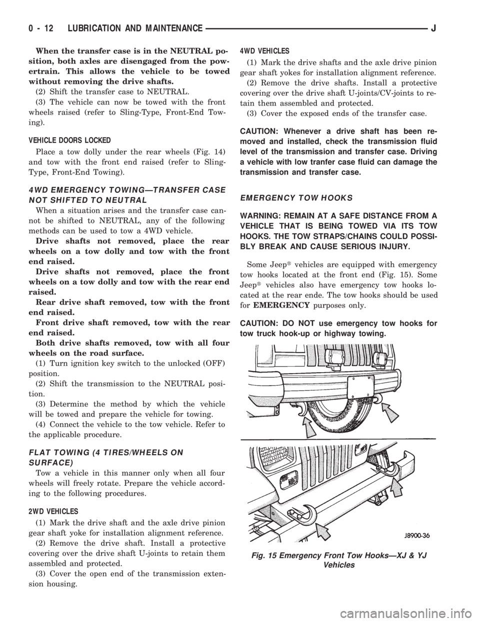
Some Jeeptvehicles are equipped with emergency
tow hooks located at the front end (Fig. 15). Some
Jeeptvehicles also have emergency tow hooks lo-
cated at the rear ende. The tow hooks should be used
forEMERGENCYpurposes only.
CAUTION: DO NOT use emergency tow hooks for
tow truck hook-up or highway towing.
Fig. 15 Emergency Front Tow HooksÐXJ & YJ
Vehicles
0 - 12 LUBRICATION AND MAINTENANCEJ
Page 1115 of 1784
(6) Remove slave cylinder from clutch housing.
(7) Disconnect transmission shift lever as follows:
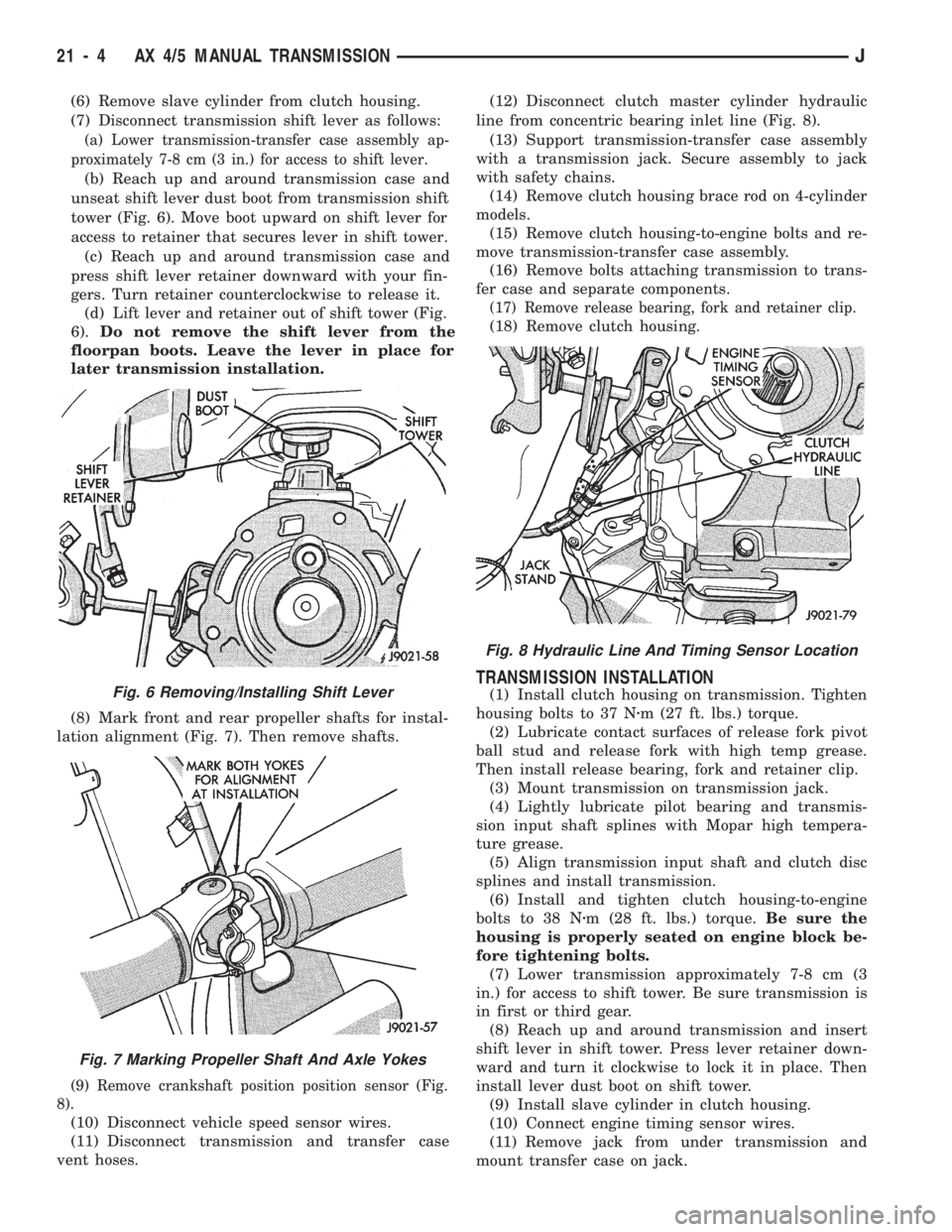
(a) Lower transmission-transfer case assembly ap-
proximately 7-8 cm (3 in.) for access to shift lever.
(b) Reach up and around transmission case and
unseat shift lever dust boot from transmission shift
tower (Fig. 6). Move boot upward on shift lever for
access to retainer that secures lever in shift tower.
(c) Reach up and around transmission case and
press shift lever retainer downward with your fin-
gers. Turn retainer counterclockwise to release it.
(d) Lift lever and retainer out of shift tower (Fig.
6).Do not remove the shift lever from the
floorpan boots. Leave the lever in place for
later transmission installation.
(8) Mark front and rear propeller shafts for instal-
lation alignment (Fig. 7). Then remove shafts.
(9) Remove crankshaft position position sensor (Fig.
8).
(10) Disconnect vehicle speed sensor wires.
(11) Disconnect transmission and transfer case
vent hoses.(12) Disconnect clutch master cylinder hydraulic
line from concentric bearing inlet line (Fig. 8).
(13) Support transmission-transfer case assembly
with a transmission jack. Secure assembly to jack
with safety chains.
(14) Remove clutch housing brace rod on 4-cylinder
models.
(15) Remove clutch housing-to-engine bolts and re-
move transmission-transfer case assembly.
(16) Remove bolts attaching transmission to trans-
fer case and separate components.
(17) Remove release bearing, fork and retainer clip.
(18) Remove clutch housing.
TRANSMISSION INSTALLATION
(1) Install clutch housing on transmission. Tighten
housing bolts to 37 Nzm (27 ft. lbs.) torque.
(2) Lubricate contact surfaces of release fork pivot
ball stud and release fork with high temp grease.
Then install release bearing, fork and retainer clip.
(3) Mount transmission on transmission jack.
(4) Lightly lubricate pilot bearing and transmis-
sion input shaft splines with Mopar high tempera-
ture grease.
(5) Align transmission input shaft and clutch disc
splines and install transmission.
(6) Install and tighten clutch housing-to-engine
bolts to 38 Nzm (28 ft. lbs.) torque.Be sure the
housing is properly seated on engine block be-
fore tightening bolts.
(7) Lower transmission approximately 7-8 cm (3
in.) for access to shift tower. Be sure transmission is
in first or third gear.
(8) Reach up and around transmission and insert
shift lever in shift tower. Press lever retainer down-
ward and turn it clockwise to lock it in place. Then
install lever dust boot on shift tower.
(9) Install slave cylinder in clutch housing.
(10) Connect engine timing sensor wires.
(11) Remove jack from under transmission and
mount transfer case on jack.Fig. 6 Removing/Installing Shift Lever
Fig. 7 Marking Propeller Shaft And Axle Yokes
Fig. 8 Hydraulic Line And Timing Sensor Location
21 - 4 AX 4/5 MANUAL TRANSMISSIONJ
Page 1146 of 1784
(9) Reach up and around transmission case and
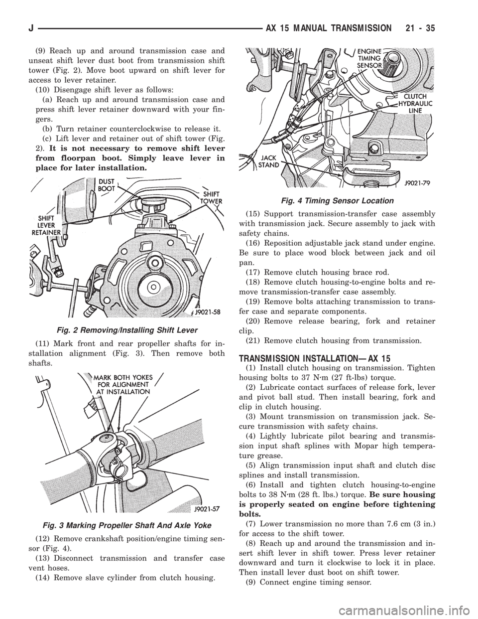
unseat shift lever dust boot from transmission shift
tower (Fig. 2). Move boot upward on shift lever for
access to lever retainer.
(10) Disengage shift lever as follows:
(a) Reach up and around transmission case and
press shift lever retainer downward with your fin-
gers.
(b) Turn retainer counterclockwise to release it.
(c) Lift lever and retainer out of shift tower (Fig.
2).It is not necessary to remove shift lever
from floorpan boot. Simply leave lever in
place for later installation.
(11) Mark front and rear propeller shafts for in-
stallation alignment (Fig. 3). Then remove both
shafts.
(12) Remove crankshaft position/engine timing sen-
sor (Fig. 4).
(13) Disconnect transmission and transfer case
vent hoses.
(14) Remove slave cylinder from clutch housing.(15) Support transmission-transfer case assembly
with transmission jack. Secure assembly to jack with
safety chains.
(16) Reposition adjustable jack stand under engine.
Be sure to place wood block between jack and oil
pan.
(17) Remove clutch housing brace rod.
(18) Remove clutch housing-to-engine bolts and re-
move transmission-transfer case assembly.
(19) Remove bolts attaching transmission to trans-
fer case and separate components.
(20) Remove release bearing, fork and retainer
clip.
(21) Remove clutch housing from transmission.
TRANSMISSION INSTALLATIONÐAX 15
(1) Install clutch housing on transmission. Tighten
housing bolts to 37 Nzm (27 ft-lbs) torque.
(2) Lubricate contact surfaces of release fork, lever
and pivot ball stud. Then install bearing, fork and
clip in clutch housing.
(3) Mount transmission on transmission jack. Se-
cure transmission with safety chains.
(4) Lightly lubricate pilot bearing and transmis-
sion input shaft splines with Mopar high tempera-
ture grease.
(5) Align transmission input shaft and clutch disc
splines and install transmission.
(6) Install and tighten clutch housing-to-engine
bolts to 38 Nzm (28 ft. lbs.) torque.Be sure housing
is properly seated on engine before tightening
bolts.
(7) Lower transmission no more than 7.6 cm (3 in.)
for access to the shift tower.
(8) Reach up and around the transmission and in-
sert shift lever in shift tower. Press lever retainer
downward and turn it clockwise to lock it in place.
Then install lever dust boot on shift tower.
(9) Connect engine timing sensor.
Fig. 2 Removing/Installing Shift Lever
Fig. 3 Marking Propeller Shaft And Axle Yoke
Fig. 4 Timing Sensor Location
JAX 15 MANUAL TRANSMISSION 21 - 35
Page 1221 of 1784
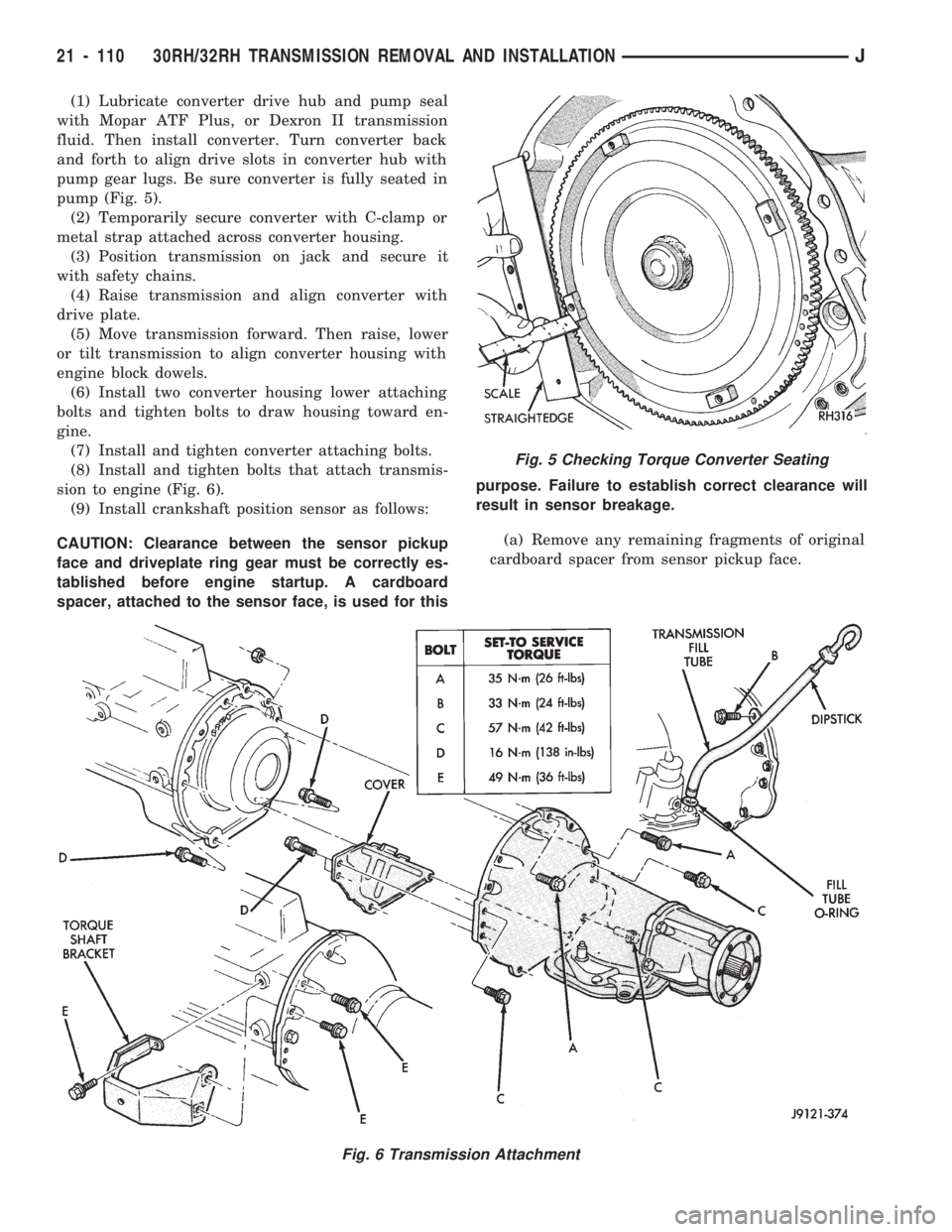
(1) Lubricate converter drive hub and pump seal
with Mopar ATF Plus, or Dexron II transmission
fluid. Then install converter. Turn converter back
and forth to align drive slots in converter hub with
pump gear lugs. Be sure converter is fully seated in
pump (Fig. 5).
(2) Temporarily secure converter with C-clamp or
metal strap attached across converter housing.
(3) Position transmission on jack and secure it
with safety chains.
(4) Raise transmission and align converter with
drive plate.
(5) Move transmission forward. Then raise, lower
or tilt transmission to align converter housing with
engine block dowels.
(6) Install two converter housing lower attaching
bolts and tighten bolts to draw housing toward en-
gine.
(7) Install and tighten converter attaching bolts.
(8) Install and tighten bolts that attach transmis-
sion to engine (Fig. 6).
(9) Install crankshaft position sensor as follows:
CAUTION: Clearance between the sensor pickup
face and driveplate ring gear must be correctly es-
tablished before engine startup. A cardboard
spacer, attached to the sensor face, is used for thispurpose. Failure to establish correct clearance will
result in sensor breakage.
(a) Remove any remaining fragments of original
cardboard spacer from sensor pickup face.
Fig. 5 Checking Torque Converter Seating
Fig. 6 Transmission Attachment
21 - 110 30RH/32RH TRANSMISSION REMOVAL AND INSTALLATIONJ
Page 1300 of 1784
AW-4 TRANSMISSION REMOVAL AND INSTALLATION
INDEX
page page
Oil Pump Seal Replacement............... 189
Torque Converter Stator Clutch Inspection..... 189Transmission and Torque Converter Installation . 190
Transmission and Torque Converter Removal . . 189
TRANSMISSION AND TORQUE CONVERTER
REMOVAL
(1) Raise vehicle.
(2) Drain transmission fluid and reinstall oil pan
drain plug.
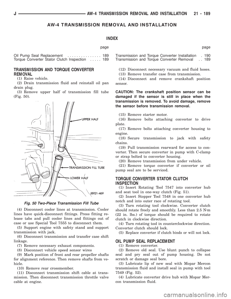
(3) Remove upper half of transmission fill tube
(Fig. 50).
(4) Disconnect cooler lines at transmission. Cooler
lines have quick-disconnect fittings. Press fitting re-
lease tabs and pull cooler lines and fittings out of
case or use Special Tool 7555 to disconnect them.
(5) Support engine with safety stand and support
transmission with jack.
(6) Disconnect transmission and transfer case shift
linkage.
(7) Remove necessary exhaust components.
(8) Disconnect vehicle speed sensor wires
(9) Mark position of front and rear propeller shafts
for alignment reference. Then remove shafts from ve-
hicle.
(10) Remove rear crossmember.
(11) Disconnect transmission shift cable at trans-
mission. Then disconnect transmission throttle valve
cable at engine.(12) Disconnect necessary vacuum and fluid hoses.
(13) Remove transfer case from transmission.
(14) Disconnect and remove crankshaft position
sensor.
CAUTION: The crankshaft position sensor can be
damaged if the sensor is still in place when the
transmission is removed. To avoid damage, remove
the sensor before transmission removal.
(15) Remove starter motor.
(16) Remove bolts attaching converter to drive
plate.
(17) Remove bolts attaching converter housing to
engine.
(18) Secure transmission to jack with safety
chains.
(19) Pull transmission rearward for access to con-
verter. Then secure converter in pump with C-clamp
or strap bolted to converter housing.
(20) Remove transmission from under vehicle.
(21) Remove torque converter if converter or oil
pump seal are to be serviced.
TORQUE CONVERTER STATOR CLUTCH
INSPECTION
(1) Insert Rotating Tool 7547 into converter hub
and seat tool in one-way clutch (Fig. 51).
(2) Insert Stopper Tool 7548 in one converter hub
notch and into outer race of rotating tool.
(3) Turn rotating tool clockwise. Converter clutch
should rotate freely and smoothly. Less than 2.5 Nzm
(22 in. lbs.) of torque should be required to rotate
clutch in clockwise direction.
(4) Turn rotating tool in counterclockwise direction.
Converter clutch should lock.
(5)
Replace converter if clutch binds or will not lock.
OIL PUMP SEAL REPLACEMENT
(1) Remove converter.
(2) Remove old seal. Use blunt punch to collapse
seal and pry seal out of pump housing. Do not
scratch or damage seal bore.
(3) Lubricate lip of new seal with Mopar Mercon
transmission fluid and install seal in pump with tool
7549 (Fig. 52).
(4) Lubricate converter drive hub with Mopar Mer-
con transmission fluid.
Fig. 50 Two-Piece Transmission Fill Tube
JAW-4 TRANSMISSION REMOVAL AND INSTALLATION 21 - 189