Page 1301 of 1784

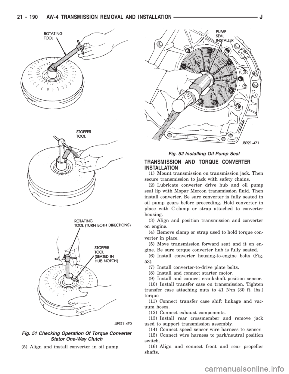
(5) Align and install converter in oil pump.
TRANSMISSION AND TORQUE CONVERTER
INSTALLATION
(1) Mount transmission on transmission jack. Then
secure transmission to jack with safety chains.
(2) Lubricate converter drive hub and oil pump
seal lip with Mopar Mercon transmission fluid. Then
install converter. Be sure converter is fully seated in
oil pump gears before proceeding. Hold converter in
place with C-clamp or strap attached to converter
housing.
(3) Align and position transmission and converter
on engine.
(4) Remove clamp or strap used to hold torque con-
verter in place.
(5) Move transmission forward seat and it on en-
gine. Be sure torque converter hub is fully seated.
(6)
Install converter housing-to-engine bolts (Fig.
53).
(7) Install converter-to-drive plate bolts.
(8) Install and connect starter motor.
(9) Install and connect crankshaft position sensor.
(10) Install transfer case on transmission. Tighten
transfer case attaching nuts to 41 Nzm (30 ft. lbs.)
torque
(11) Connect transfer case shift linkage and vac-
uum hoses.
(12) Connect exhaust components.
(13) Install rear crossmember and remove jack
used to support transmission assembly.
(14) Connect speed sensor wire harness to sensor.
(15) Connect wire harness to park/neutral position
switch.
(16) Align and connect front and rear propeller
shafts.
Fig. 51 Checking Operation Of Torque Converter
Stator One-Way Clutch
Fig. 52 Installing Oil Pump Seal
21 - 190 AW-4 TRANSMISSION REMOVAL AND INSTALLATIONJ
Page 1387 of 1784

TRANSFER CASE REMOVAL
(1) Shift transfer case into Neutral.
(2) Raise vehicle.
(3) Drain transfer case lubricant.
(4) Mark front and rear propeller shaft yokes for
alignment reference.
(5) Support transmission with jack stand.
(6) Remove rear crossmember, or skid plate.
(7) Disconnect front/rear propeller shafts at trans-
fer case.
(8) Disconnect vehicle speed sensor wires.(9) Disconnect transfer case linkage rod from range
lever.
(10) Disconnect transfer case vent hose.
(11) Support transfer case with transmission jack.
(12) Remove nuts attaching transfer case to trans-
mission.
(13) Secure transfer case to jack with chains.
(14) Pull transfer case and jack rearward to disen-
gage transfer case.
(15) Remove transfer case from under vehicle.
TRANSFER CASE INSTALLATION
(1) Mount transfer case on a transmission jack. Se-
cure transfer case to jack with chains.
(2) Position transfer case under vehicle.
(3) Align transfer case and transmission shafts and
install transfer case on transmission.
(4) Install and tighten transfer case attaching nuts
to 35 Nzm (26 ft. lbs.) torque.
(5) Connect vehicle speed sensor wires, and vent hose.
(6) Align and connect propeller shafts. Tighten
shaft attaching bolts to 19 Nzm (170 in. lbs.) torque.
(7) Fill transfer case with Mopar ATF Plus, or
Dexron II automatic transmission fluid.
(8) Install rear crossmember, or skid plate. Tighten
crossmember bolts to 41 Nzm (30 ft. lbs.) torque.
(9) Remove transmission jack and transmission
support stand.
(10) Connect transfer case range lever to linkage rod.
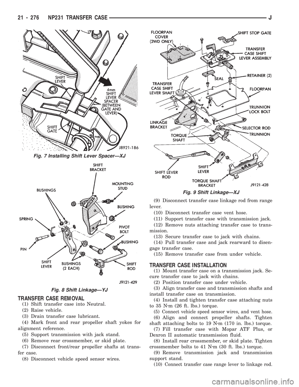
Fig. 7 Installing Shift Lever SpacerÐXJ
Fig. 8 Shift LinkageÐYJ
Fig. 9 Shift LinkageÐXJ
21 - 276 NP231 TRANSFER CASEJ
Page 1407 of 1784

SHIFT LINKAGE ADJUSTMENT
(1) Remove shift lever bezel.
(2) Move shift lever into 4L position.
(3) Insert 3 mm (1/8 in.) spacer between shift lever
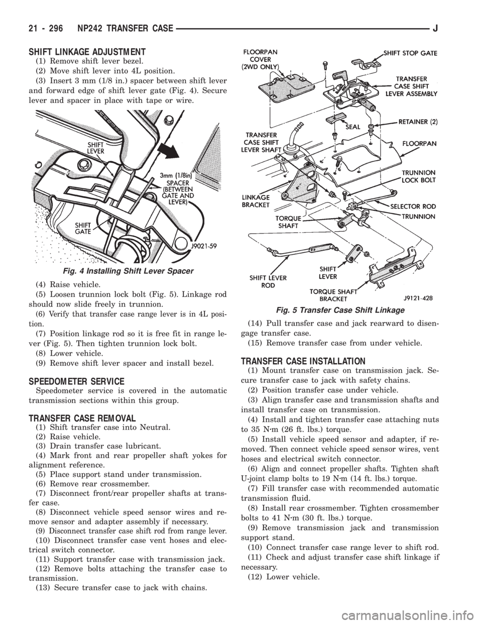
and forward edge of shift lever gate (Fig. 4). Secure
lever and spacer in place with tape or wire.
(4) Raise vehicle.
(5) Loosen trunnion lock bolt (Fig. 5). Linkage rod
should now slide freely in trunnion.
(6) Verify that transfer case range lever is in 4L posi-
tion.
(7) Position linkage rod so it is free fit in range le-
ver (Fig. 5). Then tighten trunnion lock bolt.
(8) Lower vehicle.
(9) Remove shift lever spacer and install bezel.
SPEEDOMETER SERVICE
Speedometer service is covered in the automatic
transmission sections within this group.
TRANSFER CASE REMOVAL
(1) Shift transfer case into Neutral.
(2) Raise vehicle.
(3) Drain transfer case lubricant.
(4) Mark front and rear propeller shaft yokes for
alignment reference.
(5) Place support stand under transmission.
(6) Remove rear crossmember.
(7) Disconnect front/rear propeller shafts at trans-
fer case.
(8) Disconnect vehicle speed sensor wires and re-
move sensor and adapter assembly if necessary.
(9) Disconnect transfer case shift rod from range lever.
(10) Disconnect transfer case vent hoses and elec-
trical switch connector.
(11) Support transfer case with transmission jack.
(12) Remove bolts attaching the transfer case to
transmission.
(13) Secure transfer case to jack with chains.(14) Pull transfer case and jack rearward to disen-
gage transfer case.
(15) Remove transfer case from under vehicle.
TRANSFER CASE INSTALLATION
(1) Mount transfer case on transmission jack. Se-
cure transfer case to jack with safety chains.
(2) Position transfer case under vehicle.
(3) Align transfer case and transmission shafts and
install transfer case on transmission.
(4) Install and tighten transfer case attaching nuts
to 35 Nzm (26 ft. lbs.) torque.
(5) Install vehicle speed sensor and adapter, if re-
moved. Then connect vehicle speed sensor wires, vent
hoses and electrical switch connector.
(6) Align and connect propeller shafts. Tighten shaft
U-joint clamp bolts to 19 Nzm (14 ft. lbs.) torque.
(7) Fill transfer case with recommended automatic
transmission fluid.
(8) Install rear crossmember. Tighten crossmember
bolts to 41 Nzm (30 ft. lbs.) torque.
(9) Remove transmission jack and transmission
support stand.
(10) Connect transfer case range lever to shift rod.
(11) Check and adjust transfer case shift linkage if
necessary.
(12) Lower vehicle.
Fig. 4 Installing Shift Lever Spacer
Fig. 5 Transfer Case Shift Linkage
21 - 296 NP242 TRANSFER CASEJ
Page 1445 of 1784

TIRE CHAINS
Tire snow chains may be used on certain models.
Refer to Owner's Manual for more information.
CLEANING OF TIRES
Steam cleaning may be used for cleaning.
DO NOT use gasoline or wire brush for cleaning.
DO NOT use mineral oil or an oil-based solvent.
PRESSURE GAUGES
High-quality, dial-type, air-pressure gauges are
recommended. After checking with the gauge, re-
place valve cap and finger tight.
TIRE INFLATION PRESSURES
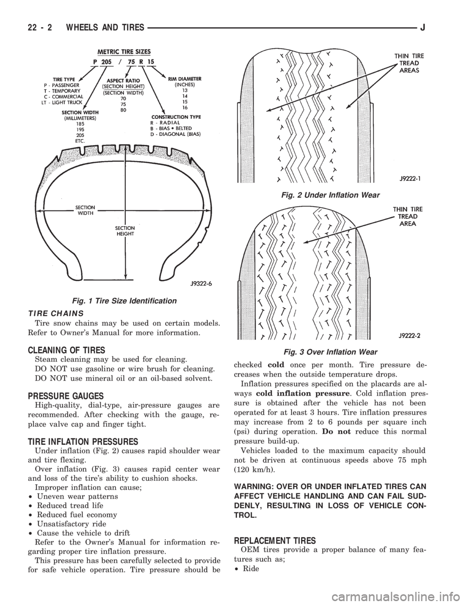
Under inflation (Fig. 2) causes rapid shoulder wear
and tire flexing.
Over inflation (Fig. 3) causes rapid center wear
and loss of the tire's ability to cushion shocks.
Improper inflation can cause;
²Uneven wear patterns
²Reduced tread life
²Reduced fuel economy
²Unsatisfactory ride
²Cause the vehicle to drift
Refer to the Owner's Manual for information re-
garding proper tire inflation pressure.
This pressure has been carefully selected to provide
for safe vehicle operation. Tire pressure should becheckedcoldonce per month. Tire pressure de-
creases when the outside temperature drops.
Inflation pressures specified on the placards are al-
wayscold inflation pressure. Cold inflation pres-
sure is obtained after the vehicle has not been
operated for at least 3 hours. Tire inflation pressures
may increase from 2 to 6 pounds per square inch
(psi) during operation.Do notreduce this normal
pressure build-up.
Vehicles loaded to the maximum capacity should
not be driven at continuous speeds above 75 mph
(120 km/h).
WARNING: OVER OR UNDER INFLATED TIRES CAN
AFFECT VEHICLE HANDLING AND CAN FAIL SUD-
DENLY, RESULTING IN LOSS OF VEHICLE CON-
TROL.
REPLACEMENT TIRES
OEM tires provide a proper balance of many fea-
tures such as;
²Ride
Fig. 1 Tire Size Identification
Fig. 2 Under Inflation Wear
Fig. 3 Over Inflation Wear
22 - 2 WHEELS AND TIRESJ