1994 JEEP CHEROKEE wiring
[x] Cancel search: wiringPage 394 of 1784
TEST PROCEDURES
INDEX
page page
Checking for Diagnostic Trouble Code......... 5
Electrical Tests at Powertrain Control Module.... 6
Electrical Tests at Servo.................... 5
Inoperative System........................ 5
Operational Check (Road Test)............... 7
Road Test............................... 5Speed Control Switch (Turn Signal Lever) Test . . . 7
Stop Lamp Speed Control Switch Test......... 7
Vacuum Supply Test....................... 7
Vehicle Speed Control System Electrical Tests . . . 5
Vehicle Speed Sensor Test.................. 5
ROAD TEST
Refer to Operational Check (Road Test) section to
verify reports of speed control system malfunction.
INOPERATIVE SYSTEM
Road test vehicle to verify reports of speed control
system malfunction. An inspection should be made
for loose electrical and vacuum connections at the
servo.
Check for correct installation of the vacuum check
valve in the hose from servo to vacuum source. The
word VAC on the valve must point toward the vac-
uum source.
Corrosion should be removed from electrical termi-
nals and a light coating of Mopar MultiPurpose
Grease, or equivalent, applied.
Inspection also should be made to verify that both
ends of the speed control cable are securely attached.
CHECKING FOR DIAGNOSTIC TROUBLE CODE
(1) When trying to verify a speed control system
electronic malfunction use a DRB scan tool to find
the cause (refer to Powertrain Diagnostic Procedures
manual).
If DRB is not available, the Diagnostic Trouble
Code (DTC) may be determined with the following
method:
(a) With key inserted in ignition switch, cycle
switch to ON position 3 times. On third cycle, leave
switch in ON position.
(b) After switch has been cycled 3 times, observe
Malfunction Indicator Lamp (CHECK ENGINE)
on instrument cluster. If a DTC is present, the code
will be displayed in a series of flashes representing
digits. Three flashes in rapid succession, a slight
pause, then 4 flashes in rapid succession would in-
dicate DTC 34.
(2) If a DTC 34 is observed, perform tests in the
sections Electrical Tests at Servo and Electrical Tests
at Powertrain Control Module.
If a DTC 15 is observed, perform test for a faulty
vehicle speed sensor.
(3) Correct any problems found when performing
these tests and recheck for DTC if changes were
made.
VEHICLE SPEED SENSOR TEST
For testing of the vehicle speed sensor and related
components, refer to Powertrain Diagnostic Proce-
dures manual.
VEHICLE SPEED CONTROL SYSTEM ELECTRICAL
TESTS
Vehicle speed control systems may be tested using
two different methods. One involves use of a DRB
scan tool. If this test method is desired, refer to Pow-
ertrain Diagnostic Procedures manual.
The other test method uses a voltmeter. The volt-
meter method is described in the following tests.
If any information is needed concerning wiring, re-
fer to Section 8W - Wiring Diagrams.
CAUTION: When test probing for voltage or conti-
nuity at electrical connectors, care must be taken
not to damage connector, terminals, or seals. If
these components are damaged, intermittent or
complete system failure may occur.
ELECTRICAL TESTS AT SERVO
(1) Turn ignition switch to the ON position. With
speed control switch in the ON position, setup a volt-
meter to read battery voltage and connect negative
lead to a good chassis ground.
(2) Disconnect 4-way connector going to servo
(Figs. 2 and 3). Blue wire with red tracer of main
harness 4-way connector should read approximately
battery voltage. If not, check for loose connections,
brake switch adjustment or, repair main harness as
necessary.
(3) Connect a jumper wire between male and fe-
male terminals of blue wire with red tracer. The
other 3 male terminals from servo should show bat-
tery voltage. If not, replace servo.
(4) Using an ohmmeter, connect one lead to a good
body ground. Touch other lead to black wire terminal
in 4-way connector of main harness. Meter should
show continuity. If not, repair ground circuit as nec-
essary.
JVEHICLE SPEED CONTROL SYSTEM 8H - 5
Page 402 of 1784

TURN SIGNALS AND HAZARD WARNING FLASHER
CONTENTS
page page
HAZARD LAMPSÐXJ.................... 1
HAZARD LAMPSÐYJ.................... 2
TURN SIGNALSÐXJ..................... 1TURN SIGNALSÐYJ..................... 2
TURN/HAZARD SWITCH REPLACEMENT - ALL
MODELS............................. 3
TURN SIGNALSÐXJ
Refer to Section 8W - Wiring Diagrams for cir-
cuit wiring diagram.
DESCRIPTION
With the turn signal lever in its up or down posi-
tion and the ignition switch in ACCESSORY or ON,
current flows through the:
²turn/hazard switch
²selected turn indicator bulb
²front and rear turn signal bulbs
²and the front side marker bulb.
With the headlamps OFF, the turn and front side
marker lamps flash in unison.With the headlamps
ON, the turn and front side marker lamps flash al-
ternately.
DIAGNOSISÐTURN SIGNAL INOPERATIVE
(1) A turn signal indicator that does not flash usu-
ally indicates a burned out turn signal bulb. Check
for and replace if defective. System should now func-
tion properly. If not, go to next step.
High generator output voltage can burn out
lamps rapidly.(2) Remove and inspect 20 amp #8 fuse. Replace if
necessary. If OK, go to next step.
(3) Remove turn flasher, light blue can, located in
upper left corner of fuse block.
(4) Turn ignition switch to ACCESSORY. Check
for battery voltage at flasher bottom cavity on fuse
block. If OK, go to next step. If not, repair open cir-
cuit in wiring between turn flasher and #8 fuse.
(5) Turn ignition switch to ACCESSORY. Move
turn signal lever up or down. Replace turn flasher
with known good flasher. The lamps should flash. If
not, replace original flasher and go to next step.
(6) Turn ignition switch to OFF. Follow procedure
for turn/hazard switch replacement to locate steering
column connector. Unplug connector.
(7) Turn ignition switch to ACCESSORY. Check
for battery voltage at connector terminal L. If OK,
replace turn/hazard switch and check that lamps
flash. If not, repair open circuit in wiring between
turn flasher and steering column connector terminal
L.
HAZARD LAMPSÐXJ
Refer to Section 8W - Wiring Diagrams for cir-
cuit wiring diagram.
DESCRIPTION
With the hazard switch ON, current flows through
the:
²hazard flasher
²the turn/hazard switch
²two front turn signal bulbs
²two rear turn signal bulbs
²two front side marker bulbs
²and two turn indicator bulbs.
All of these bulbs will flash on and off.
DIAGNOSISÐHAZARD LAMPS INOPERATIVE
(1) Inspect 20 amp #F13 fuse in Power Distribu-
tion Center (PDC). The PDC is located in the engine
compartment, passenger side. For location of fuse,check underside of PDC cover. Replace if necessary.
If OK, go to next step.
(2) Remove hazard flasher (tin can) located in fuse
block.
(3) Check for battery voltage at the terminal on
the right (3 o'clock). If OK, go to next step. If not, re-
pair open circuit in wiring between #F13 fuse and
hazard flasher right terminal.
(4) Replace hazard flasher with known good
flasher. Activate hazard warning switch. Lamps
should flash. If not, replace original flasher and go to
next step.
(5) Follow procedure for turn/hazard switch re-
placement to locate steering column connector. Un-
plug connector.
(6) Check for battery voltage at connector terminal
K. If OK, replace turn/hazard switch. If not, repair
open circuit in wiring between hazard flasher and
steering column connector terminal K.
JTURN SIGNALS AND HAZARD WARNING FLASHER 8J - 1
Page 403 of 1784

TURN SIGNALSÐYJ
Refer to Section 8W - Wiring Diagrams for cir-
cuit wiring diagram.
DESCRIPTION
With the turn signal lever in its up or down posi-
tion and the ignition switch in ACCESSORY or ON,
current flows through the:
²turn/hazard switch
²selected turn indicator bulb
²front and rear turn signal bulbs
²front side marker bulb
With the headlamps OFF, the turn and side
marker lamps flash in unison.With the headlamps
ON, the turn and side marker lamps flash alter-
nately.
DIAGNOSINGÐTURN SIGNAL INOPERATIVE
(1) A turn signal indicator that does not flash usu-
ally indicates a burned out turn signal bulb. Check
for and replace if defective. System should now func-
tion properly. If not, go to next step.
High generator output voltage can burn out
lamps rapidly.
(2) Locate fuse block under driver's side of instru-
ment panel.(3) Remove and inspect 15 amp #4 fuse. Replace if
necessary. If OK, go to next step.
(4) Remove turn flasher, light blue can, located in
fuse block.
(5) Turn ignition switch to ACCESSORY. Check
for battery voltage at cavity on left (closest to hazard
flasher can). If OK, go to next step. If not, repair
open circuit in wiring between turn flasher and #4
fuse.
(6) Turn ignition switch to ACCESSORY. Move
turn signal lever up or down. Replace turn flasher
with known good flasher. The lamps should flash. If
not, replace original flasher and go to next step.
(7) Turn ignition switch to OFF. Follow procedure
for turn/hazard switch replacement to locate steering
column connector. Unplug connector.
(8) Turn ignition switch to ACCESSORY. Check
for battery voltage at connector terminal L. If OK,
replace turn/hazard switch. If not, repair open circuit
in wiring between turn flasher and steering column
connector terminal L.
HAZARD LAMPSÐYJ
Refer to Section 8W - Wiring Diagrams for cir-
cuit wiring diagram.
DESCRIPTION
With the hazard switch ON, current flows through
the:
²hazard flasher
²turn/hazard switch
²two front turn signal bulbs
²two rear turn signal bulbs
²two front side marker bulbs
²two turn indicator bulbs.
All of these bulbs will flash on and off.
DIAGNOSISÐHAZARD LAMPS INOPERATIVE
(1) Inspect 20 amp #F5 fuse in Power Distribution
Center (PDC). The PDC is located in the engine com-
partment, passenger side. For location of fuse, check
underside of PDC cover. Replace if necessary. If OK,
go to next step.(2) Remove hazard flasher (tin can) located in fuse
block.
(3) Check for battery voltage at the terminal on
the left. If OK, go to next step. If not, repair open cir-
cuit in wiring between #F5 fuse and hazard flasher
left terminal.
(4) Replace hazard flasher with known good
flasher. Activate hazard warning switch. Lamps
should flash. If not, replace original flasher and go to
next step.
(5) Follow procedure for turn/hazard switch re-
placement to locate steering column connector. Un-
plug connector.
(6) Check for battery voltage at connector terminal
K. If OK, replace turn/hazard switch. If not, repair
open circuit in wiring between hazard flasher and
steering column connector terminal K.
8J - 2 TURN SIGNALS AND HAZARD WARNING FLASHERJ
Page 409 of 1784
WINDSHIELD WIPER MOTOR
REMOVAL
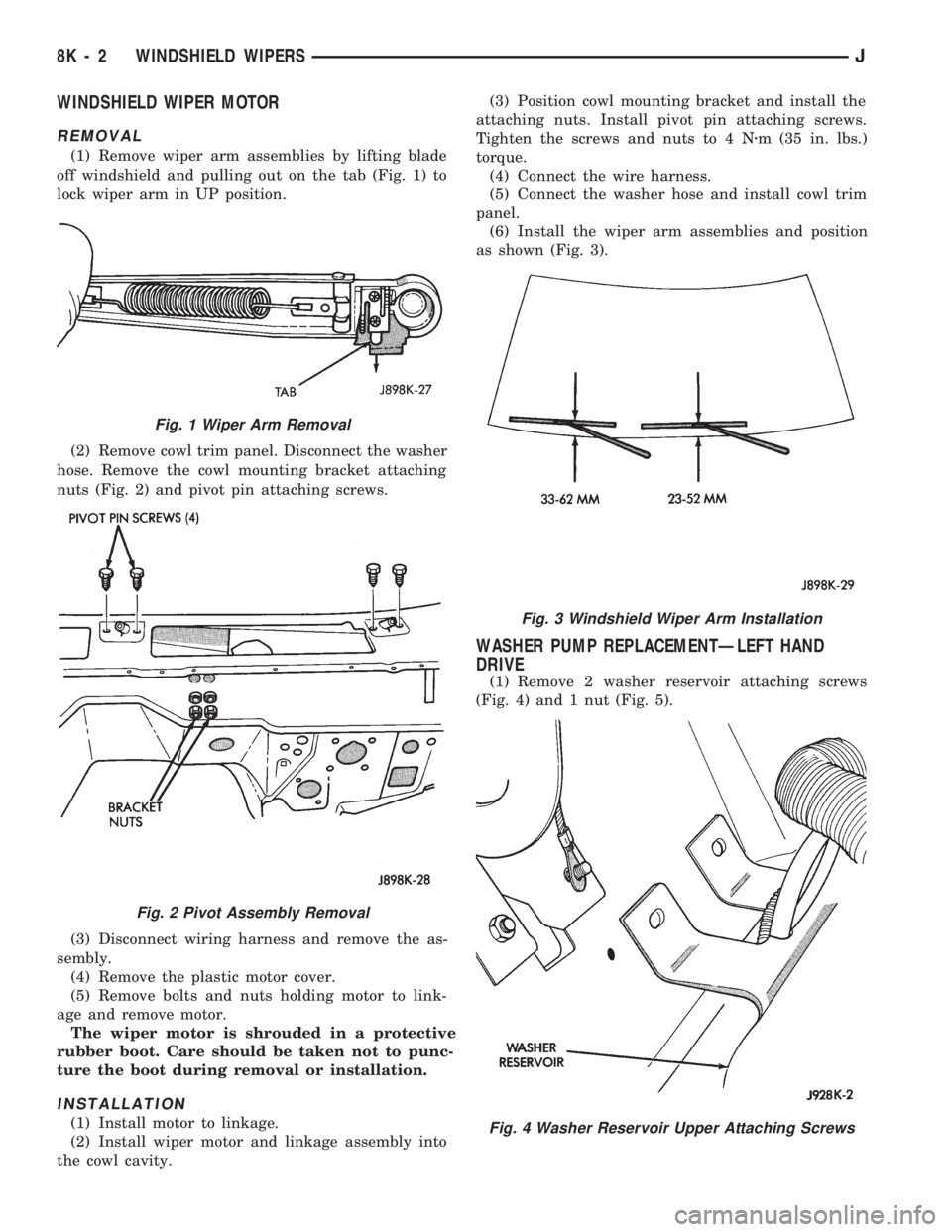
(1) Remove wiper arm assemblies by lifting blade
off windshield and pulling out on the tab (Fig. 1) to
lock wiper arm in UP position.
(2) Remove cowl trim panel. Disconnect the washer
hose. Remove the cowl mounting bracket attaching
nuts (Fig. 2) and pivot pin attaching screws.
(3) Disconnect wiring harness and remove the as-
sembly.
(4) Remove the plastic motor cover.
(5) Remove bolts and nuts holding motor to link-
age and remove motor.
The wiper motor is shrouded in a protective
rubber boot. Care should be taken not to punc-
ture the boot during removal or installation.
INSTALLATION
(1) Install motor to linkage.
(2) Install wiper motor and linkage assembly into
the cowl cavity.(3) Position cowl mounting bracket and install the
attaching nuts. Install pivot pin attaching screws.
Tighten the screws and nuts to 4 Nzm (35 in. lbs.)
torque.
(4) Connect the wire harness.
(5) Connect the washer hose and install cowl trim
panel.
(6) Install the wiper arm assemblies and position
as shown (Fig. 3).
WASHER PUMP REPLACEMENTÐLEFT HAND
DRIVE
(1) Remove 2 washer reservoir attaching screws
(Fig. 4) and 1 nut (Fig. 5).
Fig. 1 Wiper Arm Removal
Fig. 2 Pivot Assembly Removal
Fig. 3 Windshield Wiper Arm Installation
Fig. 4 Washer Reservoir Upper Attaching Screws
8K - 2 WINDSHIELD WIPERSJ
Page 410 of 1784
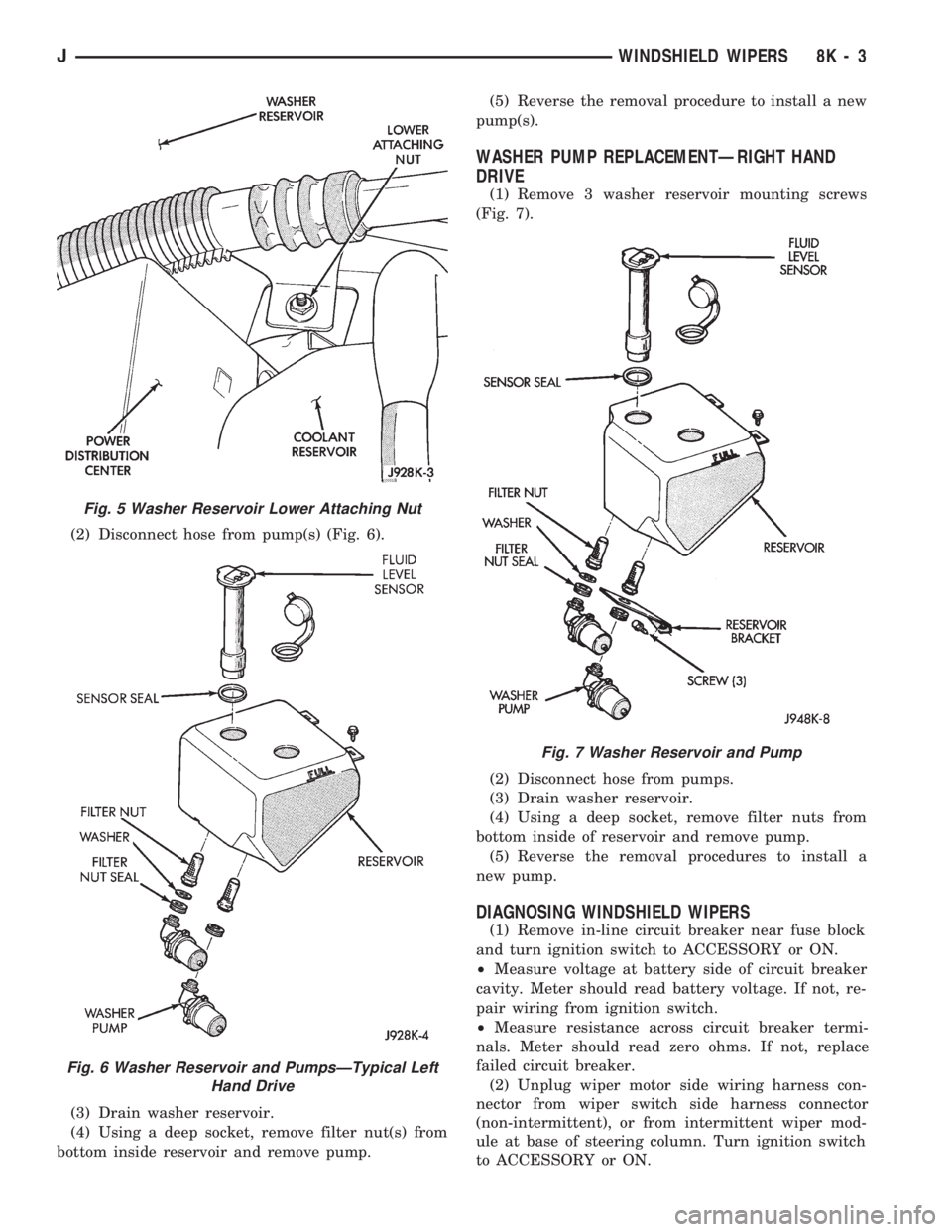
(2) Disconnect hose from pump(s) (Fig. 6).
(3) Drain washer reservoir.
(4) Using a deep socket, remove filter nut(s) from
bottom inside reservoir and remove pump.(5) Reverse the removal procedure to install a new
pump(s).
WASHER PUMP REPLACEMENTÐRIGHT HAND
DRIVE
(1) Remove 3 washer reservoir mounting screws
(Fig. 7).
(2) Disconnect hose from pumps.
(3) Drain washer reservoir.
(4) Using a deep socket, remove filter nuts from
bottom inside of reservoir and remove pump.
(5) Reverse the removal procedures to install a
new pump.
DIAGNOSING WINDSHIELD WIPERS
(1) Remove in-line circuit breaker near fuse block
and turn ignition switch to ACCESSORY or ON.
²Measure voltage at battery side of circuit breaker
cavity. Meter should read battery voltage. If not, re-
pair wiring from ignition switch.
²Measure resistance across circuit breaker termi-
nals. Meter should read zero ohms. If not, replace
failed circuit breaker.
(2) Unplug wiper motor side wiring harness con-
nector from wiper switch side harness connector
(non-intermittent), or from intermittent wiper mod-
ule at base of steering column. Turn ignition switch
to ACCESSORY or ON.
Fig. 5 Washer Reservoir Lower Attaching Nut
Fig. 6 Washer Reservoir and PumpsÐTypical Left
Hand Drive
Fig. 7 Washer Reservoir and Pump
JWINDSHIELD WIPERS 8K - 3
Page 411 of 1784
²Measure voltage at unplugged wiper motor side
harness connector terminal D. Meter should read
battery voltage. If not, repair wiring from circuit
breaker.
²Turn ignition switch to OFF and measure resis-
tance from unplugged wiper motor side harness con-
nector terminal G to ground. Meter should read zero
ohms. If not, repair wiring to ground.
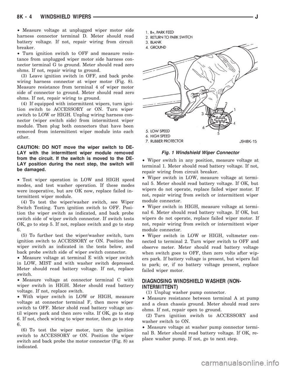
(3) Leave ignition switch in OFF, and back probe
wiring harness connector at wiper motor (Fig. 8).
Measure resistance from terminal 4 of wiper motor
side of connector to ground. Meter should read zero
ohms. If not, repair wiring to ground.
(4) If equipped with intermittent wipers, turn igni-
tion switch to ACCESSORY or ON. Turn wiper
switch to LOW or HIGH. Unplug wiring harness con-
nector (wiper switch side) from intermittent wiper
module. Then plug both connectors that have been
removed from intermittent wiper module into each
other.
CAUTION: DO NOT move the wiper switch to DE-
LAY with the intermittent wiper module removed
from the circuit. If the switch is moved to the DE-
LAY position during the next step, the switch will
be damaged.
²Test wiper operation in LOW and HIGH speed
modes, and test washer operation. If these modes
were inoperative, but are OK now, replace failed in-
termittent wiper module.
(4) To test the wiper/washer switch, see Wiper
Switch Testing. Turn ignition switch to OFF. Posi-
tion the wiper switch as indicated, and back probe
switch side of wiper switch connector. If switch tests
OK, go to step 5. If not, replace switch and go to step
6.
(5) To further test the wiper/washer switch, turn
ignition switch to ACCESSORY or ON. Position the
wiper switch as indicated in the tests below, and
back probe switch side of wiper switch connector.
²Measure voltage at terminal E with wiper switch
in LOW, MIST and with washer switch depressed.
Meter should read battery voltage. If not, replace
switch.
²Measure voltage at connector terminal C with
wiper switch in HIGH. Meter should read battery
voltage. If not, replace switch.
²With wiper switch in LOW or HIGH, measure
voltage at connector terminal F, then move wiper
switch to OFF. Meter shold read battery voltage un-
til wipers park and then zero volts. If OK, go to step
6. If not, check wiring to wiper motor, then go to step
6.
(6) To test the wiper motor, turn the ignition
switch to ACCESSORY or ON. Position the wiper
switch and back probe the motor connector (Fig. 8) as
indicated.²Wiper switch in any position, measure voltage at
terminal 1. Meter should read battery voltage. If not,
repair wiring from circuit breaker.
²Wiper switch in LOW, measure voltage at termi-
nal 5. Meter should read battery voltage. If OK, but
wipers do not operate, replace failed wiper motor. If
not, repair wiring from switch or intermittent wiper
module connector.
²Wiper switch in HIGH, measure voltage at termi-
nal 6. Meter should read battery voltage. If OK, but
wipers do not operate, replace failed wiper motor. If
not, repair wiring from switch or intermittent wiper
module connector.
²Wiper switch in LOW or HIGH, voltmeter con-
nected to terminal 2. Turn wiper switch to OFF and
observe meter. Meter should read battery voltage
when switch goes to OFF, then zero volts after wip-
ers park. If battery voltage is present, but wipers fail
to park; or, if no battery voltage present, replace
failed wiper motor.
DIAGNOSING WINDSHIELD WASHER (NON-
INTERMITTENT)
(1) Unplug washer pump connector.
²Measure resistance between terminal A at pump
and a clean chassis ground. Meter should read zero
ohms. If not, repair open to ground.
(2) Turn ignition switch to ACCESSORY and
washer switch to ON.
²Measure voltage at washer pump connector termi-
nal B. Meter should read battery voltage. If OK, re-
place washer pump. If not, go to next step.
Fig. 1 Windshield Wiper Connector
8K - 4 WINDSHIELD WIPERSJ
Page 412 of 1784
²Measure voltage at wiper/washer switch connector
terminal B. Meter should read battery voltage. If
OK, repair open to washer pump. If not, replace
switch.
DIAGNOSING WINDSHIELD WASHER
(INTERMITTENT)
(1) Unplug washer pump connector.
²Measure resistance between terminal B at pump
and a clean chassis ground. Meter should read zero
ohms. If not, repair open to ground.
(2) Turn ignition switch to ACCESSORY and
washer switch to ON.
²Measure voltage at wipe module switch connector
terminal B (pink wire). Meter should read battery
voltage. If not, replace wiper switch.
²Measure voltage at wipe module motor connector
terminal B (brown wire). Meter should read battery
voltage. If not, replace module.
²Measure voltage at washer pump connector termi-
nal A at pump. Meter should read battery voltage. If
OK, replace pump. If not, repair open from wipe
module.
INTERMITTENT WIPER MODULE
The intermittent wiper module is non-serviceable.
Refer to the wiring schematic for connector call outs.
The intermittent wiper module is attached to the
lower instrument panel cover near the steering col-
umn with a patch of velcro.
LIFTGATE WIPER
GENERAL
The rear wiper motor contains electronic controls
to provide three operating modes.
²Intermittent wipe witha5to8second delay be-
tween sweeps.
²Constant wipe that operates in conjunction with a
washer.
²Park mode that operates when ignition or rear
wiper switch is turned OFF.
The rear wiper switch is located in the instrument
panel and is supplied current when the ignition
switch is in the ON position. When the switch is
placed in the intermittent wipe position it provides
current to the rear wiper motor. When it is held in
the wash/wipe position it provides current to both the
motor and the rear washer pump. The switch is
spring loaded in the wash/wipe position.
REMOVAL
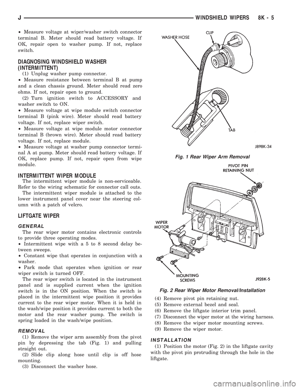
(1) Remove the wiper arm assembly from the pivot
pin by depressing the tab (Fig. 1) and pulling
straight out.
(2) Slide clip along hose until clip is off hose
mounting.
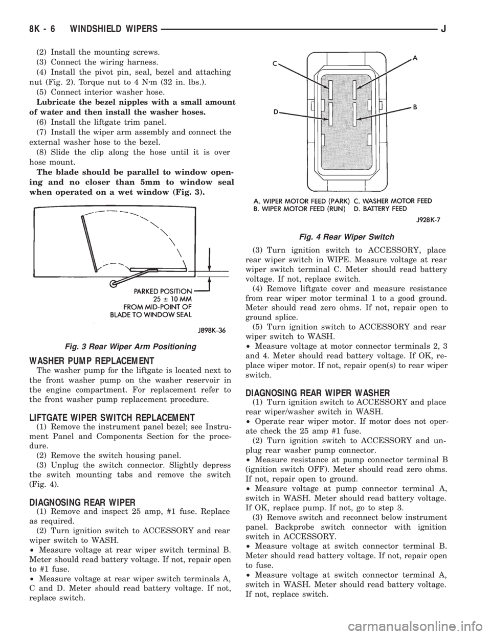
(3) Disconnect the washer hose.(4) Remove pivot pin retaining nut.
(5) Remove external bezel and seal.
(6) Remove the liftgate interior trim panel.
(7) Disconnect the wiper motor at the wiring harness.
(8) Remove the wiper motor mounting screws.
(9) Remove the wiper motor.
INSTALLATION
(1) Position the motor (Fig. 2) in the liftgate cavity
with the pivot pin protruding through the hole in the
liftgate.
Fig. 1 Rear Wiper Arm Removal
Fig. 2 Rear Wiper Motor Removal/Installation
JWINDSHIELD WIPERS 8K - 5
Page 413 of 1784
(2) Install the mounting screws.
(3) Connect the wiring harness.
(4) Install the pivot pin, seal, bezel and attaching
nut (Fig. 2). Torque nut to 4 Nzm (32 in. lbs.).
(5) Connect interior washer hose.
Lubricate the bezel nipples with a small amount
of water and then install the washer hoses.
(6) Install the liftgate trim panel.
(7) Install the wiper arm assembly and connect the
external washer hose to the bezel.
(8) Slide the clip along the hose until it is over
hose mount.
The blade should be parallel to window open-
ing and no closer than 5mm to window seal
when operated on a wet window (Fig. 3).
WASHER PUMP REPLACEMENT
The washer pump for the liftgate is located next to
the front washer pump on the washer reservoir in
the engine compartment. For replacement refer to
the front washer pump replacement procedure.
LIFTGATE WIPER SWITCH REPLACEMENT
(1) Remove the instrument panel bezel; see Instru-
ment Panel and Components Section for the proce-
dure.
(2) Remove the switch housing panel.
(3) Unplug the switch connector. Slightly depress
the switch mounting tabs and remove the switch
(Fig. 4).
DIAGNOSING REAR WIPER
(1) Remove and inspect 25 amp, #1 fuse. Replace
as required.
(2) Turn ignition switch to ACCESSORY and rear
wiper switch to WASH.
²Measure voltage at rear wiper switch terminal B.
Meter should read battery voltage. If not, repair open
to #1 fuse.
²Measure voltage at rear wiper switch terminals A,
C and D. Meter should read battery voltage. If not,
replace switch.(3) Turn ignition switch to ACCESSORY, place
rear wiper switch in WIPE. Measure voltage at rear
wiper switch terminal C. Meter should read battery
voltage. If not, replace switch.
(4) Remove liftgate cover and measure resistance
from rear wiper motor terminal 1 to a good ground.
Meter should read zero ohms. If not, repair open to
ground splice.
(5) Turn ignition switch to ACCESSORY and rear
wiper switch to WASH.
²Measure voltage at motor connector terminals 2, 3
and 4. Meter should read battery voltage. If OK, re-
place wiper motor. If not, repair open(s) to rear wiper
switch.
DIAGNOSING REAR WIPER WASHER
(1) Turn ignition switch to ACCESSORY and place
rear wiper/washer switch in WASH.
²Operate rear wiper motor. If motor does not oper-
ate check the 25 amp #1 fuse.
(2) Turn ignition switch to ACCESSORY and un-
plug rear washer pump connector.
²Measure resistance at pump connector terminal B
(ignition switch OFF). Meter should read zero ohms.
If not, repair open to ground.
²Measure voltage at pump connector terminal A,
switch in WASH. Meter should read battery voltage.
If OK, replace pump. If not, go to step 3.
(3) Remove switch and reconnect below instrument
panel. Backprobe switch connector with ignition
switch in ACCESSORY.
²Measure voltage at switch connector terminal B.
Meter should read battery voltage. If not, repair open
to fuse.
²Measure voltage at switch connector terminal A,
switch in WASH. Meter should read battery voltage.
If not, replace switch.
Fig. 3 Rear Wiper Arm Positioning
Fig. 4 Rear Wiper Switch
8K - 6 WINDSHIELD WIPERSJ