1994 JEEP CHEROKEE center console
[x] Cancel search: center consolePage 1692 of 1784
(4) Connect the heater hoses to the heater core.
(5) Fill the cooling system.
HEATER CORE HOUSING REPLACEMENT
(1) Remove the evaporator/blower housing.
(2) Remove the heater core.
(3) Remove the defroster duct.
(4) Disconnect the vacuum hoses from the heater
core housing vacuum motors.
(5) Remove the heater housing retaining nuts in
the engine compartment. Remove the heater core
housing.
(6) Transfer the vacuum motors, etc. to the re-
placement housing.
To install the heater core housing, reverse the re-
moval procedure.
DEFROSTER DUCT REPLACEMENT
REMOVAL
(1) Disconnect negative cable from battery.
(2) If equipped with center console remove the con-
sole as follows:
(a) MANUAL TRANSMISSIONÐRemove shift
knob, boot and bezel.
(b) AUTOMATIC TRANSMISSIONÐRemove
shift handle by pulling up. Remove the shift bezel.
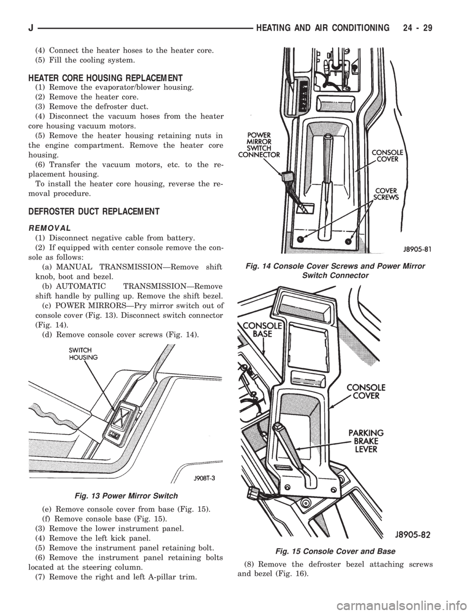
(c) POWER MIRRORSÐPry mirror switch out of
console cover (Fig. 13). Disconnect switch connector
(Fig. 14).
(d) Remove console cover screws (Fig. 14).
(e) Remove console cover from base (Fig. 15).
(f) Remove console base (Fig. 15).
(3) Remove the lower instrument panel.
(4) Remove the left kick panel.
(5) Remove the instrument panel retaining bolt.
(6) Remove the instrument panel retaining bolts
located at the steering column.
(7) Remove the right and left A-pillar trim.(8) Remove the defroster bezel attaching screws
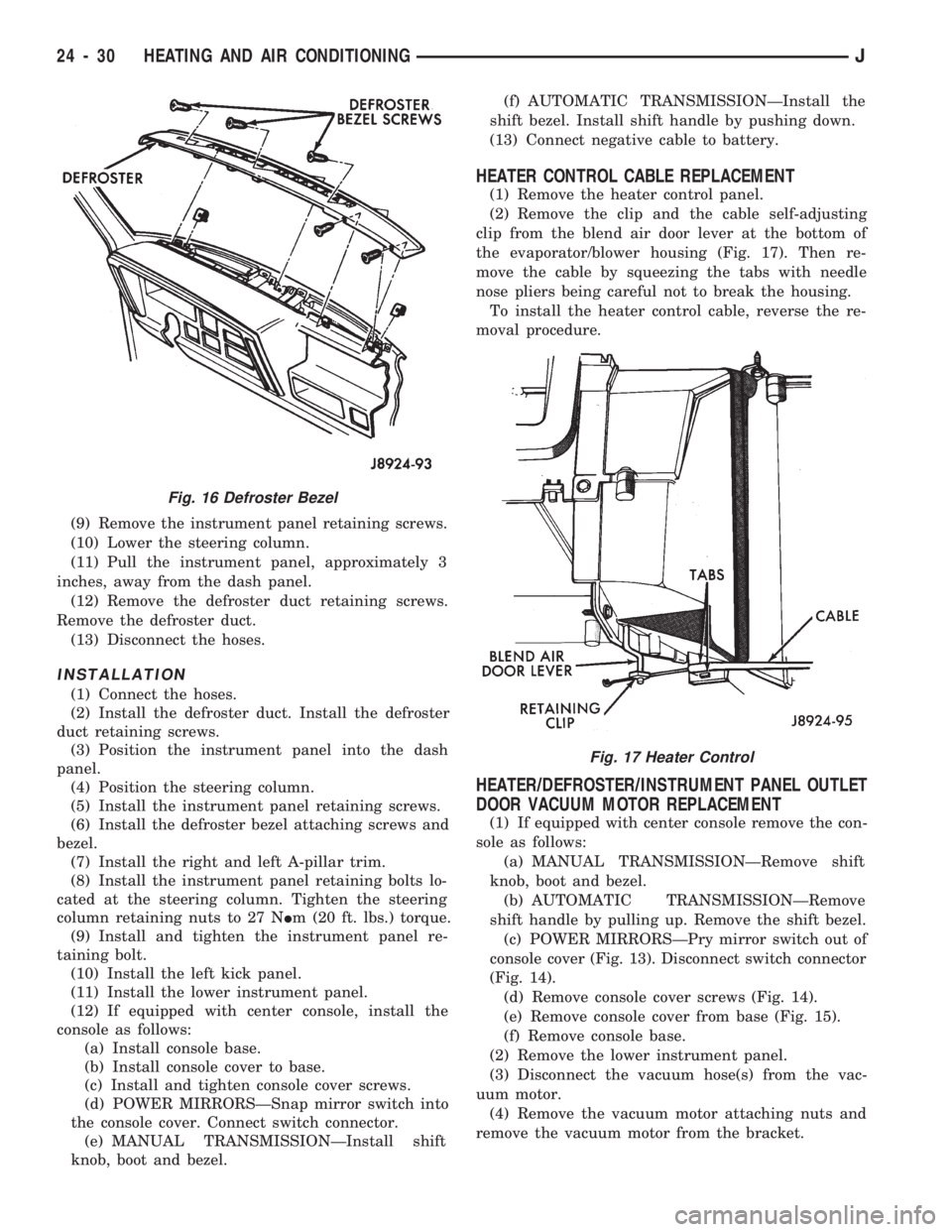
and bezel (Fig. 16).
Fig. 13 Power Mirror Switch
Fig. 14 Console Cover Screws and Power Mirror
Switch Connector
Fig. 15 Console Cover and Base
JHEATING AND AIR CONDITIONING 24 - 29
Page 1693 of 1784
(9) Remove the instrument panel retaining screws.
(10) Lower the steering column.
(11) Pull the instrument panel, approximately 3
inches, away from the dash panel.
(12) Remove the defroster duct retaining screws.
Remove the defroster duct.
(13) Disconnect the hoses.
INSTALLATION
(1) Connect the hoses.
(2) Install the defroster duct. Install the defroster
duct retaining screws.
(3) Position the instrument panel into the dash
panel.
(4) Position the steering column.
(5) Install the instrument panel retaining screws.
(6) Install the defroster bezel attaching screws and
bezel.
(7) Install the right and left A-pillar trim.
(8) Install the instrument panel retaining bolts lo-
cated at the steering column. Tighten the steering
column retaining nuts to 27 NIm (20 ft. lbs.) torque.
(9) Install and tighten the instrument panel re-
taining bolt.
(10) Install the left kick panel.
(11) Install the lower instrument panel.
(12) If equipped with center console, install the
console as follows:
(a) Install console base.
(b) Install console cover to base.
(c) Install and tighten console cover screws.
(d) POWER MIRRORSÐSnap mirror switch into
the console cover. Connect switch connector.
(e) MANUAL TRANSMISSIONÐInstall shift
knob, boot and bezel.(f) AUTOMATIC TRANSMISSIONÐInstall the
shift bezel. Install shift handle by pushing down.
(13) Connect negative cable to battery.
HEATER CONTROL CABLE REPLACEMENT
(1) Remove the heater control panel.
(2) Remove the clip and the cable self-adjusting
clip from the blend air door lever at the bottom of
the evaporator/blower housing (Fig. 17). Then re-
move the cable by squeezing the tabs with needle
nose pliers being careful not to break the housing.
To install the heater control cable, reverse the re-
moval procedure.
HEATER/DEFROSTER/INSTRUMENT PANEL OUTLET
DOOR VACUUM MOTOR REPLACEMENT
(1) If equipped with center console remove the con-
sole as follows:
(a) MANUAL TRANSMISSIONÐRemove shift
knob, boot and bezel.
(b) AUTOMATIC TRANSMISSIONÐRemove
shift handle by pulling up. Remove the shift bezel.
(c) POWER MIRRORSÐPry mirror switch out of
console cover (Fig. 13). Disconnect switch connector
(Fig. 14).
(d) Remove console cover screws (Fig. 14).
(e) Remove console cover from base (Fig. 15).
(f) Remove console base.
(2) Remove the lower instrument panel.
(3) Disconnect the vacuum hose(s) from the vac-
uum motor.
(4) Remove the vacuum motor attaching nuts and
remove the vacuum motor from the bracket.
Fig. 16 Defroster Bezel
Fig. 17 Heater Control
24 - 30 HEATING AND AIR CONDITIONINGJ
Page 1696 of 1784
EVAPORATOR/BLOWER HOUSING
REMOVAL
(1) Disconnect negative cable from battery.
(2) Discharge the A/C system as described in this
section and disconnect the A/C hoses from the expan-
sion valve.
(3) Disconnect the blower motor wires and the vent
tube.
(4) If equipped with center console remove the con-
sole as follows:
(a) MANUAL TRANSMISSIONÐRemove shift
knob, boot and bezel.
(b) AUTOMATIC TRANSMISSIONÐRemove
shift handle by pulling up. Remove the shift bezel.
(c) POWER MIRRORSÐPry mirror switch out of
console cover (Fig. 13) and disconnect switch con-
nector (Fig. 14).
(d) Remove console cover screws (Fig. 14).
(e) Remove console cover from base (Fig. 15).
(f) Remove console base.
(5) Remove the lower instrument panel.
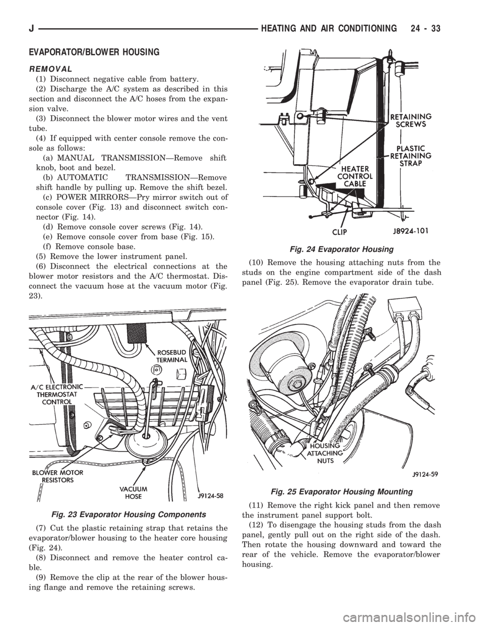
(6) Disconnect the electrical connections at the
blower motor resistors and the A/C thermostat. Dis-
connect the vacuum hose at the vacuum motor (Fig.
23).
(7) Cut the plastic retaining strap that retains the
evaporator/blower housing to the heater core housing
(Fig. 24).
(8) Disconnect and remove the heater control ca-
ble.
(9) Remove the clip at the rear of the blower hous-
ing flange and remove the retaining screws.(10) Remove the housing attaching nuts from the
studs on the engine compartment side of the dash
panel (Fig. 25). Remove the evaporator drain tube.
(11) Remove the right kick panel and then remove
the instrument panel support bolt.
(12) To disengage the housing studs from the dash
panel, gently pull out on the right side of the dash.
Then rotate the housing downward and toward the
rear of the vehicle. Remove the evaporator/blower
housing.
Fig. 23 Evaporator Housing Components
Fig. 24 Evaporator Housing
Fig. 25 Evaporator Housing Mounting
JHEATING AND AIR CONDITIONING 24 - 33
Page 1698 of 1784
(5) Install the evaporator/blower housing.
(6) Add 30 ml (1 fluid oz.) of refrigerant oil to the
air conditioning system if the evaporator was re-
placed.
EXPANSION (H) VALVE
REMOVAL
(1) Discharge the A/C system.
(2) Remove the coolant bottle and bracket.
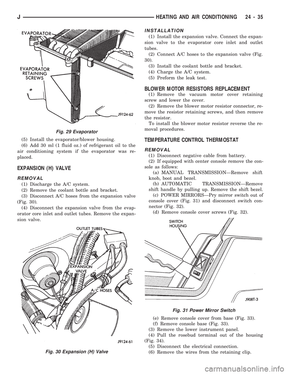
(3) Disconnect A/C hoses from the expansion valve
(Fig. 30).
(4) Disconnect the expansion valve from the evap-
orator core inlet and outlet tubes. Remove the expan-
sion valve.
INSTALLATION
(1) Install the expansion valve. Connect the expan-
sion valve to the evaporator core inlet and outlet
tubes.
(2) Connect A/C hoses to the expansion valve (Fig.
30).
(3) Install the coolant bottle and bracket.
(4) Charge the A/C system.
(5) Preform the leak test.
BLOWER MOTOR RESISTORS REPLACEMENT
(1) Remove the vacuum motor cover retaining
screw and lower the cover.
(2) Remove the blower motor resistor connector, re-
move the resistor retaining screws, and then remove
the resistor.
To install the blower motor resistor reverse the re-
moval procedures.
TEMPERATURE CONTROL THERMOSTAT
REMOVAL
(1) Disconnect negative cable from battery.
(2) If equipped with center console remove the con-
sole as follows:
(a) MANUAL TRANSMISSIONÐRemove shift
knob, boot and bezel.
(b) AUTOMATIC TRANSMISSIONÐRemove
shift handle by pulling up. Remove the shift bezel.
(c) POWER MIRRORSÐPry mirror switch out of
console cover (Fig. 31) and disconnect switch con-
nector (Fig. 32).
(d) Remove console cover screws (Fig. 32).
(e) Remove console cover from base (Fig. 33).
(f) Remove console base (Fig. 33).
(3) Remove the lower instrument panel.
(4) Pull the rosebud terminal out of the housing
(Fig. 34).
(5) Disconnect the electrical connection.
(6) Remove the wires from the retaining clip.
Fig. 29 Evaporator
Fig. 30 Expansion (H) Valve
Fig. 31 Power Mirror Switch
JHEATING AND AIR CONDITIONING 24 - 35
Page 1757 of 1784
INSTRUMENT PANEL ILLUMINATION
LAMPS............................8E-16
INSTRUMENT PANEL LAMPS..............8E-4
INSTRUMENT PANEL REPLACEMENT.......8E-8
INSTRUMENT PANEL SERVICE..........23-192
INSULATION PANEL, DASH PANEL........23-95
INSULATOR PANEL, DASH PANEL.........23-11
INSULATOR PANEL, HOOD..............23-138
INTAKE AIR TEMPERATURE SENSOR......14-54
INTAKE AIR TEMPERATURE SENSORÐ
PCM INPUT.........................14-20
INTAKE AIR TEMPERATURE SENSOR TEST . . . 14-43
INTAKE DUCT, FRESH AIR...............24-41
INTAKE MANIFOLD.....................14-57
INTAKE MANIFOLDÐ2.5L ENGINE..........11-8
INTAKE MANIFOLDÐ4.0L ENGINE..........11-9
INTAKE MANIFOLD AIR TEMPERATURE
SENSOR.......................8D-5,8D-27
INTAKE MANIFOLD AIR TEMPERATURE
SENSOR TEST.......................8D-14
INTAKE MANIFOLD LEAKAGE DIAGNOSIS.....9-5
INTERCHANGEABILITY, PARTS............21-66
INTERIOR COMPONENTS..........23-91,23-190
INTERIOR LAMPS......................8L-19
INTERIOR LAMPS, XJ..................8L-23
INTERIOR LAMPS, YJ..................8L-23
INTERIOR PAINT CODES, XJ............23-205
INTERIOR PAINT CODES, YJ............23-206
INTERIOR REARVIEW MIRROR...........23-74
INTERIOR REARVIEW MIRROR
SUPPORT BRACKET REPLACEMENT......23-75
INTERIOR TRIM PANELS AND SCUFF
PLATESÐXJ VEHICLES...............23-112
INTERLOCK CABLE ADJUSTMENT (XJ),
PARK........................21-97,21-186
INTERMEDIATE (COUPLING) SHAFT . . 19-21,19-43
INTERMITTENT WINDSHIELD WASHER,
DIAGNOSING........................8K-12
INTERMITTENT WIPER MODULE...........8K-5
INTERMITTENT WIPER WASHER..........8K-20
INTERNATIONAL VEHICLE CONTROL
AND DISPLAY SYMBOLS............INTRO.-3
IN-VEHICLE SERVICE, 30RH/32RH.........21-96
IN-VEHICLE SERVICE, AW-4.............21-173
ISOLATION, COMPRESSOR..............24-17
JACK STORAGEÐXJ VEHICLES..........23-127
JOINT ANGLE MEASUREMENT,
UNIVERSAL..........................16-4
JOINT REPLACEMENT, UNIVERSAL.........16-9
JOINTS, UNIVERSAL....................16-2
JOUNCE BUMPER, REAR................13-18
JUMP STARTING........................0-7
JUMP STARTING, HOISTING AND TOWING.....0-7
KEY LOCK CYLINDER, DOOR.............23-54
KEY LOCK CYLINDER, FULL-METAL
DOOR............................23-178
KEY LOCK CYLINDERS.............23-2,23-132
KEY WARNING SWITCH REPLACEMENT,
IGNITION............................8U-4
KEYLESS ENTRY.......................8P-8
KNOCK, LOW SPEED; FRONT
SUSPENSION AND AXLE................2-17
KNOCK, LOW SPEED; REAR SUSPENSION
AND AXLES...........................3-8
KNUCKLE AND BALL STUDS, STEERING.....2-30
LABEL, TIRE INFLATION PRESSURE.....INTRO.-3
LABEL, VEHICLE EMISSION CONTROL
INFORMATION (VECI)
..................25-1
LABEL, VEHICLE SAFETY CERTIFICATION
. INTRO.-1
LABELS/DECALS/PLATES
...........23-1,23-132
LABELS/PLATES, CODES AND
DIMENSIONS, DESIGNATIONS,
.......INTRO.-1
LAG TEST, TIME
......................21-169
LAMP, 4WD INDICATOR
..................8E-2
LAMP, ANTI-LOCK BRAKE SYSTEM (ABS)
INDICATOR
..........................8E-2
LAMP BEAM ADJUSTMENT, FOG
..........8L-12
LAMP, BRAKE INDICATOR; INSTRUMENT
PANEL AND GAUGESÐXJ
...............8E-2
LAMP, BRAKE INDICATOR; INSTRUMENT
PANEL AND GAUGESÐYJ
..............8E-16
LAMP BULB REPLACEMENT, BACK-UP/
REAR TURN SIGNAL/TAIL
...............8L-9
LAMP BULB REPLACEMENT, FRONT PARK/
TURN SIGNAL
........................8L-8LAMP BULB REPLACEMENT, SIDE
MARKER............................8L-7
LAMP BULB REPLACEMENT,
UNDERHOOD........................8L-18
LAMP BULB REPLACEMENTÐYJ
VEHICLES, HARDTOP DOME/CARGO.....8L-20
LAMP BULB/ELEMENT REPLACEMENT,
FOG ...............................8L-13
LAMP (CHECK ENGINE), MALFUNCTION
INDICATOR; INSTRUMENT PANEL
AND GAUGESÐXJ................8E-2,8E-4
LAMP (CHECK ENGINE), MALFUNCTION
INDICATOR; INSTRUMENT PANEL
AND GAUGESÐYJ...................8E-16
LAMP (CHMSL)ÐXJ, CENTER HIGH
MOUNTED STOP.....................8L-10
LAMP (CHMSL)ÐYJ, CENTER HIGH
MOUNTED STOP.....................8L-11
LAMP, COOLANT TEMPERATURE
INDICATOR..........................8E-1
LAMP FOR DIAGNOSTIC TROUBLE CODES,
INDICATOR (CHECK ENGINE)...........8A-19
LAMP HOUSING, LIFTGATE LICENSE
PLATE .............................23-72
LAMP, I/P ASH RECEIVER TRAY..........23-92
LAMP, LICENSE PLATE..................8L-10
LAMP, LOW FUEL WARNING..............8E-2
LAMPÐPCM OUTPUT, EMR..............14-24
LAMPÐPCM OUTPUT, GENERATOR.......14-25
LAMPÐPCM OUTPUT, MALFUNCTION
INDICATOR.........................14-26
LAMP REPLACEMENT, DOME.............8L-20
LAMP REPLACEMENT, FOG..............8L-15
LAMP REPLACEMENT, UNDERHOOD.......8L-18
LAMP, SEAT BELT REMINDER............8E-16
LAMP SERVICE INFORMATION, DOME/
COURTESY.........................8L-19
LAMP SERVICE INFORMATION, FOG.......8L-12
LAMP SERVICE INFORMATION,
UNDERHOOD........................8L-17
LAMP, SERVICE REMINDER INDICATOR
(SRI)...............................25-1
LAMP SPEED CONTROL SWITCH TEST,
STOP...............................8H-7
LAMP SUPPORT BRACKET, I/P TWEETER
SPEAKER/COURTESY.................23-95
LAMP SWITCH REPLACEMENT, FOG.......8L-14
LAMP TROUBLE DIAGNOSIS, DOME/
COURTESY.........................8L-19
LAMP TROUBLE DIAGNOSIS, FOG.........8L-12
LAMP, UPSHIFT INDICATOR;
INSTRUMENT PANELAND GAUGESÐXJ....8E-2
LAMP, UPSHIFT INDICATOR;
INSTRUMENT PANELAND GAUGESÐYJ . . . 8E-16
LAMPÐYJ RENEGADE VEHICLES, FOG....23-150
LAMP/REAR WIPER SWITCHES, REAR
DEFOGGER/FOG......................8E-21
LAMPS, EXTERIOR......................8L-1
LAMPS, INDICATOR....................8E-14
LAMPS INOPERATIVE, DIAGNOSISÐ
HAZARD.........................8J-1,8J-2
LAMPS, INSTRUMENT PANEL.............8E-4
LAMPS, INSTRUMENT PANEL
ILLUMINATION......................8E-16
LAMPS, INTERIOR.....................8L-19
LAMPS OUT, DIAGNOSINGÐALL..........8E-16
LAMPS, XJ EXTERIOR..................8L-23
LAMPSÐXJ, HAZARD...................8J-1
LAMPS, XJ INTERIOR..................8L-23
LAMPS, YJ EXTERIOR..................8L-23
LAMPSÐYJ, HAZARD...................8J-2
LAMPS, YJ INTERIOR..................8L-23
LATCH ADJUSTMENT, DOOR.............23-55
LATCH AND RELEASE HANDLE,
TAILGATE..........................23-160
LATCH ASSEMBLY REPLACEMENT,
SOLENOID...........................8P-6
LATCH, DOOR.........................23-56
LATCH EXTERNAL RELEASE HANDLE,
FULL-METAL DOOR..................23-178
LATCH, FULL-METAL DOOR
.............23-179
LATCH, HOOD SAFETY
.................23-139
LATCH INSIDE RELEASE AND LOCK
HANDLE, FULL-METAL DOOR
..........23-175
LATCH RELEASE AND LOCK RODS,
DOOR INSIDE
.......................23-57LATCH RELEASE CABLE REPLACEMENT....23-10
LATCH REPLACEMENT, HOOD............23-10
LATCH STRIKER AND BUMPERÐXJ
VEHICLES, REAR SEATBACK...........23-111
LATCH STRIKER, HALF-METAL DOOR.....23-175
LATCH STRIKER REPLACEMENT, HOOD....23-10
LATCH STRIKER REPLACEMENT, SAFETY . . . 23-10
LATCH STRIKER, TAILGATE.............23-161
LATCH/KEY LOCK CYLINDER/STRIKER,
LIFTGATE...........................23-68
LEAD CORRECTION CHART...............22-5
LEAF SPRING; FRONT SUSPENSION AND
AXLE...............................2-14
LEAF SPRING; REAR SUSPENSION AND
AXLES............................3-3,3-6
LEAF SPRING EYE BUSHING
REPLACEMENT; FRONT SUSPENSION
AND AXLE...........................2-15
LEAF SPRING EYE BUSHING
REPLACEMENT; REAR SUSPENSION
AND AXLES........................3-4,3-6
LEAK DETECTION AND REPAIR, FIXED
GLASS WATER................23-83,23-189
LEAK DIAGNOSIS, CONVERTER HOUSING . . . 21-73
LEAK DOWN TEST, FUEL PRESSURE........14-7
LEAK TEST, REFRIGERANT................24-8
LEAKAGE DIAGNOSIS, GEAR
..............19-8
LEAKAGE DIAGNOSIS, INTAKE
MANIFOLD
............................9-5
LEAKAGE DIAGNOSIS, PUMP
..............19-8
LEAKAGE TEST, CYLINDER COMBUSTION
PRESSURE
...........................9-6
LEAKAGE TEST DIAGNOSIS, CYLINDER
COMBUSTION PRESSURE
................9-6
LEAKS, REPAIRING
.....................22-3
LEAKS, TESTING COOLING SYSTEM FOR
....7-18
LEFT HAND DRIVE, DRIVERS DOOR
POWER LOCK SWITCHÐ2-DOOR
.........8P-2
LEFT HAND DRIVE, DRIVERS DOOR
POWER WINDOW SWITCHÐ2-DOOR
......8S-6
LETTERS, JEEP BODY CODE
...............5-2
LEVEL AND CONDITION, CHECKING
FLUID
.......................21-96,21-173
LEVEL AND CONDITION, FLUID
...........21-69
LEVEL, BRAKE FLUID
....................5-13
LEVELÐBRAKELINES AND HOSES,
BRAKE BLEEDINGÐBRAKE FLUID
........5-13
LEVEL, CLUTCH FLUID
...................6-14
LEVEL, COMPRESSOR OIL
................24-6
LEVEL, CORRECT FLUID
.................5-48
LEVEL, TRANSFER CASE FILL
...........21-294
LEVELS, OPERATING SOUND
...............5-3
LEVER INSTALLATION (XJ WITH FULL
CONSOLE), PARKING BRAKE
............5-60
LEVER INSTALLATION (XJ WITH MINI
CONSOLE), PARKING BRAKE
............5-58
LEVER INSTALLATION (XJ WITHOUT
CONSOLE), PARKING BRAKE
............5-60
LEVER POSITIONS, TRANSMISSION
RANGES AND SHIFT
.................21-157
LEVER REMOVAL (XJ WITH FULL
CONSOLE), PARKING BRAKE
............5-59
LEVER REMOVAL (XJ WITH MINI
CONSOLE), PARKING BRAKE
............5-58
LEVER REMOVAL (XJ WITHOUT
CONSOLE), PARKING BRAKE
............5-60
LICENSE PLATE LAMP
..................8L-10
LICENSE PLATE LAMP HOUSING,
LIFTGATE
...........................23-72
LICENSE PLATE SCREW ANCHOR
AND BUMPER, LIFTGATE
..............23-72
LIFTGATE ADJUSTMENT
.................23-70
LIFTGATE GLASS, HARD TOP
............23-162
LIFTGATE GLASS WEATHERSTRIP SEAL
REPLACEMENT
.....................23-163
LIFTGATE HINGE
.......................23-67
LIFTGATE LATCH/KEY LOCK CYLINDER/
STRIKER
...........................23-68
LIFTGATE LICENSE PLATE LAMP
HOUSING
...........................23-72
LIFTGATE LICENSE PLATE SCREW
ANCHOR AND BUMPER
...............23-72
JINDEX13
Description Group-Page Description Group-Page Description Group-Page