1994 JEEP CHEROKEE four wheel drive
[x] Cancel search: four wheel drivePage 1026 of 1784
SERVICE DIAGNOSIS/PROCEDURES
INDEX
page page
Runout................................. 4
Unbalance............................... 3Universal Joint Angle Measurement............ 4
Vibration................................ 3
VIBRATION
Tires that are out-of-round or wheels that are un-
balanced will cause a low frequency vibration. Refer
to Group 22, Wheels and Tires for additional infor-
mation.
Brake drums that are unbalanced will cause a
harsh, low frequency vibration. Refer to Group 5,
Brakes for additional information.
Driveline vibration can also result from loose or
damaged engine mounts. Refer to Group 21, Trans-
missions for additional information.
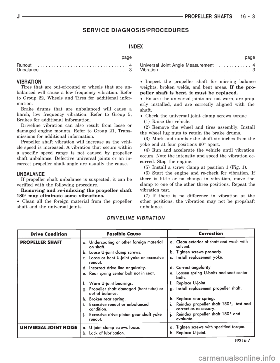
Propeller shaft vibration will increase as the vehi-
cle speed is increased. A vibration that occurs within
a specific speed range is not caused by propeller
shaft unbalance. Defective universal joints or an in-
correct propeller shaft angle are usually the cause.
UNBALANCE
If propeller shaft unbalance is suspected, it can be
verified with the following procedure.
Removing and re-indexing the propeller shaft
180É may eliminate some vibrations.
²Clean all the foreign material from the propeller
shaft and the universal joints.²Inspect the propeller shaft for missing balance
weights, broken welds, and bent areas.If the pro-
peller shaft is bent, it must be replaced.
²Ensure the universal joints are not worn, are prop-
erly installed, and are correctly aligned with the
shaft.
²Check the universal joint clamp screws torque
(1) Raise the vehicle.
(2) Remove the wheel and tires assembly. Install
the wheel lug nuts to retain the brake drums.
(3) Mark and number the shaft six inches from the
yoke end at four positions 90É apart.
(4) Run and accelerate the vehicle until vibration
occurs. Note the intensity and speed the vibration oc-
curred. Stop the engine.
(5) Install a screw clamp at position 1 (Fig. 1).
(6) Start the engine and re-check for vibration. If
there is little or no change in vibration, move the
clamp to one of the other three positions. Repeat the
vibration test.
(7) If there is no difference in vibration at the
other positions, the vibration may not be propshaft
unbalance.
DRIVELINE VIBRATION
JPROPELLER SHAFTS 16 - 3
Page 1084 of 1784
(1) Make sure the front wheels are in thestraight
aheadposition.
(2) Disconnect the negative (ground) cable from
the battery.
(3) Remove steering wheel from column, refer to
Steering Wheel-Removal.
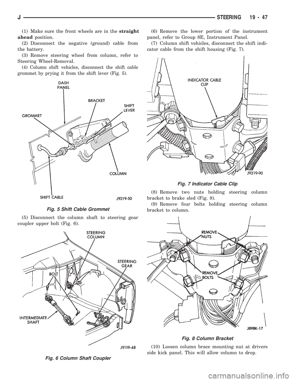
(4) Column shift vehicles, disconnect the shift cable
grommet by prying it from the shift lever (Fig. 5).
(5) Disconnect the column shaft to steering gear
coupler upper bolt (Fig. 6).(6) Remove the lower portion of the instrument
panel, refer to Group 8E, Instrument Panel.
(7) Column shift vehicles, disconnect the shift indi-
cator cable from the shift housing (Fig. 7).
(8) Remove two nuts holding steering column
bracket to brake sled (Fig. 8).
(9) Remove four bolts holding steering column
bracket to column.
(10) Loosen column brace mounting nut at drivers
side kick panel. This will allow column to drop.
Fig. 5 Shift Cable Grommet
Fig. 6 Column Shaft Coupler
Fig. 7 Indicator Cable Clip
Fig. 8 Column Bracket
JSTEERING 19 - 47
Page 1143 of 1784
AX 15 MANUAL TRANSMISSION
INDEX
page page
General Information....................... 32
Service Diagnosis........................ 33
Transmission Assembly and Adjustment....... 51
Transmission Disassembly and Overhaul....... 36
Transmission Gear Ratios.................. 33
Transmission Identification.................. 32Transmission InstallationÐAX 15............. 35
Transmission Lubricant.................... 33
Transmission RemovalÐAX 15.............. 34
Transmission Shift Pattern.................. 33
Transmission Switch and Plug Locations....... 33
GENERAL INFORMATION
The AX 15 is a 5-speed, synchromesh, manual
transmission. Fifth gear is an overdrive range with a
ratio of 0.79:1. The shift mechanism is integral and
mounted in the shift tower portion of the adapter
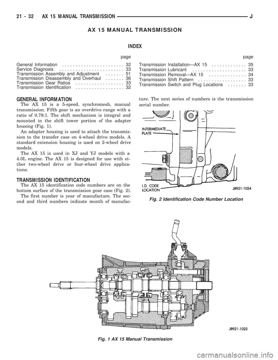
housing (Fig. 1).
An adapter housing is used to attach the transmis-
sion to the transfer case on 4-wheel drive models. A
standard extension housing is used on 2-wheel drive
models.
The AX 15 is used in XJ and YJ models with a
4.0L engine. The AX 15 is designed for use with ei-
ther two-wheel drive or four-wheel drive applica-
tions.
TRANSMISSION IDENTIFICATION
The AX 15 identification code numbers are on the
bottom surface of the transmission gear case (Fig. 2).
The first number is year of manufacture. The sec-
ond and third numbers indicate month of manufac-ture. The next series of numbers is the transmission
serial number.
Fig. 1 AX 15 Manual Transmission
Fig. 2 Identification Code Number Location
21 - 32 AX 15 MANUAL TRANSMISSIONJ
Page 1144 of 1784
TRANSMISSION SHIFT PATTERN
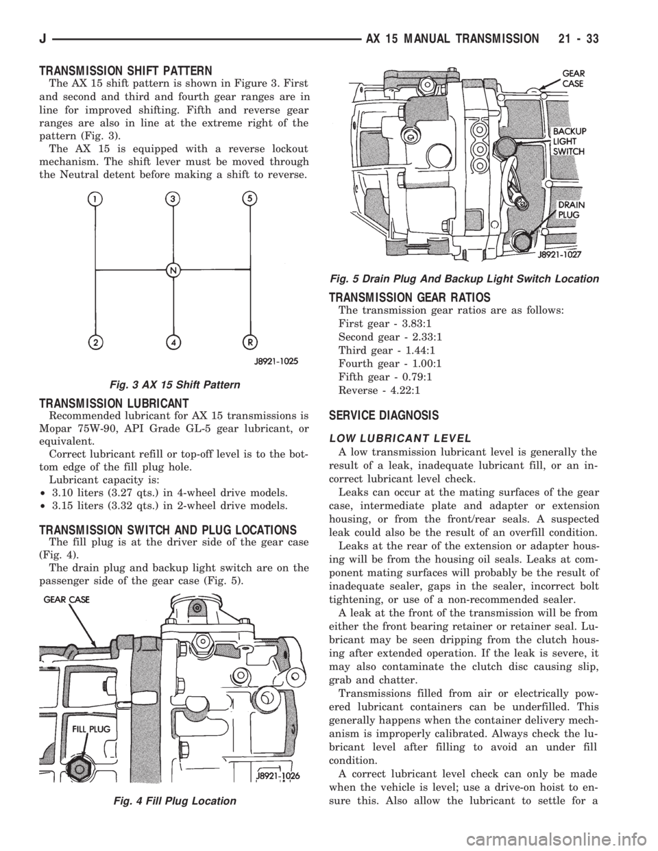
The AX 15 shift pattern is shown in Figure 3. First
and second and third and fourth gear ranges are in
line for improved shifting. Fifth and reverse gear
ranges are also in line at the extreme right of the
pattern (Fig. 3).
The AX 15 is equipped with a reverse lockout
mechanism. The shift lever must be moved through
the Neutral detent before making a shift to reverse.
TRANSMISSION LUBRICANT
Recommended lubricant for AX 15 transmissions is
Mopar 75W-90, API Grade GL-5 gear lubricant, or
equivalent.
Correct lubricant refill or top-off level is to the bot-
tom edge of the fill plug hole.
Lubricant capacity is:
²3.10 liters (3.27 qts.) in 4-wheel drive models.
²3.15 liters (3.32 qts.) in 2-wheel drive models.
TRANSMISSION SWITCH AND PLUG LOCATIONS
The fill plug is at the driver side of the gear case
(Fig. 4).
The drain plug and backup light switch are on the
passenger side of the gear case (Fig. 5).
TRANSMISSION GEAR RATIOS
The transmission gear ratios are as follows:
First gear - 3.83:1
Second gear - 2.33:1
Third gear - 1.44:1
Fourth gear - 1.00:1
Fifth gear - 0.79:1
Reverse - 4.22:1
SERVICE DIAGNOSIS
LOW LUBRICANT LEVEL
A low transmission lubricant level is generally the
result of a leak, inadequate lubricant fill, or an in-
correct lubricant level check.
Leaks can occur at the mating surfaces of the gear
case, intermediate plate and adapter or extension
housing, or from the front/rear seals. A suspected
leak could also be the result of an overfill condition.
Leaks at the rear of the extension or adapter hous-
ing will be from the housing oil seals. Leaks at com-
ponent mating surfaces will probably be the result of
inadequate sealer, gaps in the sealer, incorrect bolt
tightening, or use of a non-recommended sealer.
A leak at the front of the transmission will be from
either the front bearing retainer or retainer seal. Lu-
bricant may be seen dripping from the clutch hous-
ing after extended operation. If the leak is severe, it
may also contaminate the clutch disc causing slip,
grab and chatter.
Transmissions filled from air or electrically pow-
ered lubricant containers can be underfilled. This
generally happens when the container delivery mech-
anism is improperly calibrated. Always check the lu-
bricant level after filling to avoid an under fill
condition.
A correct lubricant level check can only be made
when the vehicle is level; use a drive-on hoist to en-
sure this. Also allow the lubricant to settle for a
Fig. 3 AX 15 Shift Pattern
Fig. 4 Fill Plug Location
Fig. 5 Drain Plug And Backup Light Switch Location
JAX 15 MANUAL TRANSMISSION 21 - 33
Page 1279 of 1784
(2) Verify transmission throttle cable operation.
Repair or replace cable if necessary.
(3) Check engine throttle operation. Operate accel-
erator pedal and observe injector throttle plate move-
ment. Adjust linkage if throttle plate does not reach
wide open position.
(4) Check transmission fluid level when fluid is at
normal operating temperature. Start engine. Shift
transmission through all gear ranges then back to
Neutral. Correct level is to Full or Add mark on dip-
stick with engine at curb idle speed.
(5) Check and adjust park/neutral position switch
if necessary.
(6) Check throttle position sensor adjustment and
operation. Adjust the sensor if necessary.
MANUAL SHIFTING TEST
(1) This test determines if problem is related to
mechanical or electrical component.
(2) Stop engine and disconnect transmission con-
trol module or module fuse.
(3) Road test vehicle. Shift transmission into each
gear range. Transmission should operate as follows:
²lock in Park
²back up in Reverse
²not move in Neutral
²provide first gear only with shift lever in 1-2 posi-
tion
²operate in third gear only with shift lever in 3 po-
sition
²operate in overdrive fourth gear in D position
(4) If transmission operates as described, proceed
to next step. However, if forward gear ranges were
difficult to distinguish (all feel the same), or vehicle
would not back up, refer to diagnosis charts. Do not
perform stall or time lag tests.
CAUTION: Do not overspeed the engine during the
next test step. Ease off the throttle and allow the
vehicle to slow before downshifting.
(5) Continue road test. Manually downshift trans-
mission from D to 3, and from 3 to 1-2 position. Then
manually upshift transmission through forward
ranges again.
(6) If transmission operation is OK, perform stall,
time lag and pressure tests. If transmission shifting
problem is encountered, refer to diagnosis charts.
(7) If a problem still exists, continue testing with
DRB II scan tool.
HYDRAULIC PRESSURE TEST
PRESSURE TEST PROCEDURE
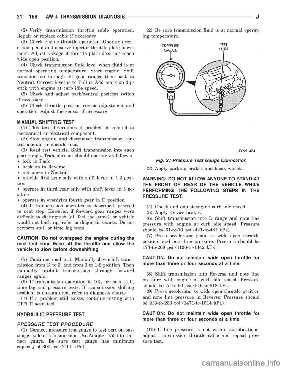
(1) Connect pressure test gauge to test port on pas-
senger side of transmission. Use Adapter 7554 to con-
nect gauge. Be sure test gauge has minimum
capacity of 300 psi (2100 kPa).(2) Be sure transmission fluid is at normal operat-
ing temperature.
(3) Apply parking brakes and block wheels.
WARNING: DO NOT ALLOW ANYONE TO STAND AT
THE FRONT OR REAR OF THE VEHICLE WHILE
PERFORMING THE FOLLOWING STEPS IN THE
PRESSURE TEST.
(4) Check and adjust engine curb idle speed.
(5) Apply service brakes.
(6) Shift transmission into D range and note line
pressure with engine at curb idle speed. Pressure
should be 61-to-70 psi (421-to-481 kPa).
(7) Press accelerator pedal to wide open throttle
position and note line pressure. Pressure should be
173-to-209 psi (1196-to-1442 kPa).
CAUTION: Do not maintain wide open throttle for
more than three or four seconds at a time.
(8) Shift transmission into Reverse and note line
pressure with engine at curb idle speed. Pressure
should be 75-to-90 psi (519-to-618 kPa).
(9) Press accelerator to wide open throttle position
and note line pressure in Reverse. Pressure should
be 213-to-263 psi (1471-to-1814 kPa).
CAUTION: Do not maintain wide open throttle for
more than three or four seconds at a time.
(10) If line pressure is not within specifications,
adjust transmission throttle cable and repeat pres-
sure test.
Fig. 27 Pressure Test Gauge Connection
21 - 168 AW-4 TRANSMISSION DIAGNOSISJ
Page 1404 of 1784
NP242 TRANSFER CASE
INDEX
page page
Cleaning and Inspection.................. 305
General Information...................... 293
Shift Linkage Adjustment.................. 296
Speedometer Service.................... 296
Transfer Case Assembly.................. 306
Transfer Case Disassembly and Overhaul..... 297Transfer Case Fill Level.................. 294
Transfer Case Identification................ 293
Transfer Case Installation................. 296
Transfer Case Lubricant.................. 294
Transfer Case Removal................... 296
GENERAL INFORMATION
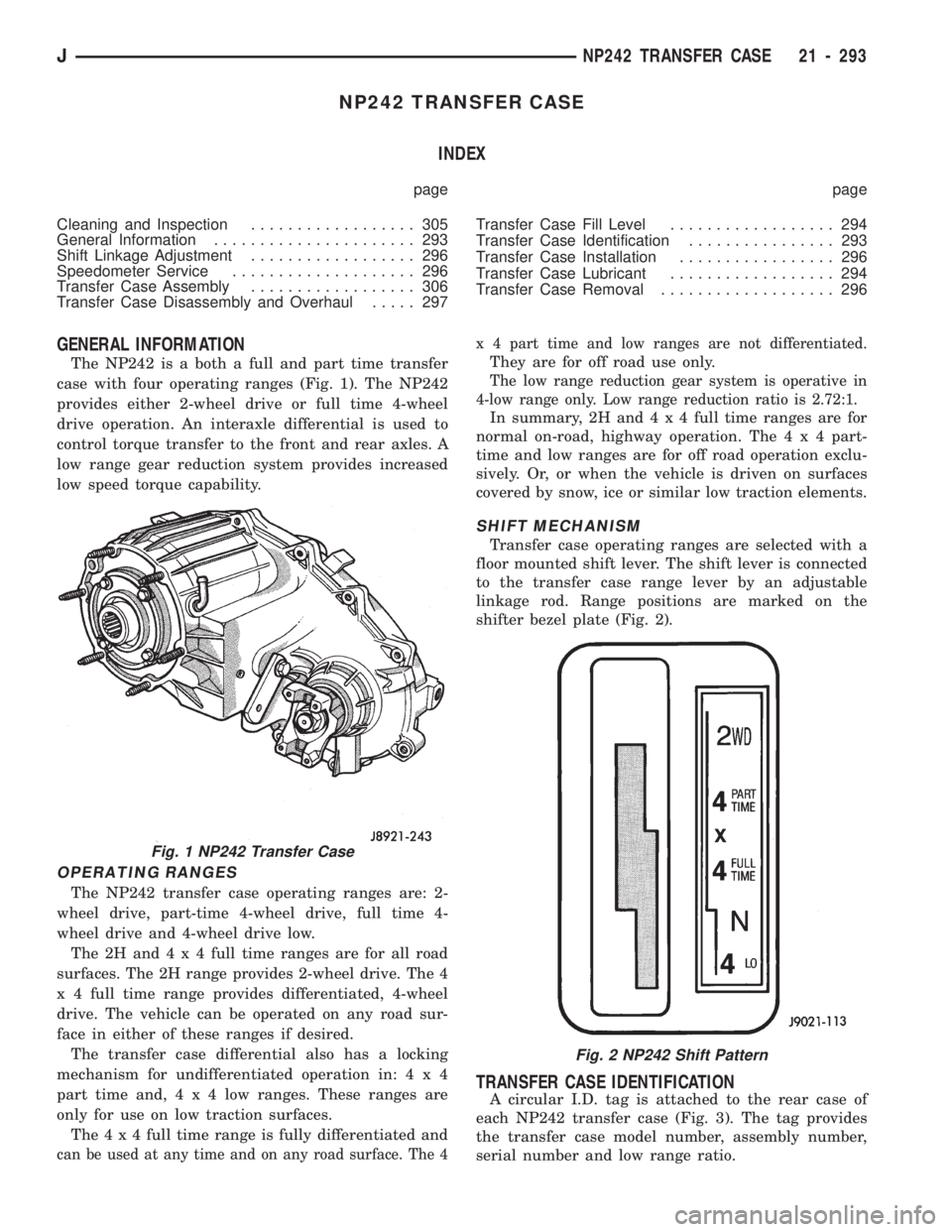
The NP242 is a both a full and part time transfer
case with four operating ranges (Fig. 1). The NP242
provides either 2-wheel drive or full time 4-wheel
drive operation. An interaxle differential is used to
control torque transfer to the front and rear axles. A
low range gear reduction system provides increased
low speed torque capability.
OPERATING RANGES
The NP242 transfer case operating ranges are: 2-
wheel drive, part-time 4-wheel drive, full time 4-
wheel drive and 4-wheel drive low.
The2Hand4x4full time ranges are for all road
surfaces. The 2H range provides 2-wheel drive. The 4
x 4 full time range provides differentiated, 4-wheel
drive. The vehicle can be operated on any road sur-
face in either of these ranges if desired.
The transfer case differential also has a locking
mechanism for undifferentiated operation in:4x4
part time and,4x4lowranges. These ranges are
only for use on low traction surfaces.
The4x4full time range is fully differentiated and
can be used at any time and on any road surface. The 4x 4 part time and low ranges are not differentiated.
They are for off road use only.
The low range reduction gear system is operative in
4-low range only. Low range reduction ratio is 2.72:1.
In summary, 2H and4x4full time ranges are for
normal on-road, highway operation. The4x4part-
time and low ranges are for off road operation exclu-
sively. Or, or when the vehicle is driven on surfaces
covered by snow, ice or similar low traction elements.
SHIFT MECHANISM
Transfer case operating ranges are selected with a
floor mounted shift lever. The shift lever is connected
to the transfer case range lever by an adjustable
linkage rod. Range positions are marked on the
shifter bezel plate (Fig. 2).
TRANSFER CASE IDENTIFICATION
A circular I.D. tag is attached to the rear case of
each NP242 transfer case (Fig. 3). The tag provides
the transfer case model number, assembly number,
serial number and low range ratio.
Fig. 1 NP242 Transfer Case
Fig. 2 NP242 Shift Pattern
JNP242 TRANSFER CASE 21 - 293
Page 1444 of 1784
WHEELS AND TIRES
CONTENTS
page page
SPECIFICATIONS....................... 11
TIRES................................. 1VEHICLE VIBRATION..................... 9
WHEELS............................... 6
TIRES
INDEX
page page
Cleaning of Tires.......................... 2
General Information........................ 1
Pressure Gauges......................... 2
Repairing Leaks.......................... 3
Replacement Tires........................ 2Rotation................................ 3
Tire Inflation Pressures..................... 2
Tire Noise or Vibration..................... 4
Tire Wear Patterns........................ 4
Tread Wear Indicators...................... 3
GENERAL INFORMATION
Tires are designed for each specific vehicle. They
provide the best overall performance for normal op-
eration. The ride and handling characteristics match
the vehicle's requirements. With proper care they
will give excellent reliability, traction, skid resis-
tance, and tread life. These tires have specific load
carrying capacities. When correctly inflated, they
will operate properly.
Tires used in cool climates, and with light loads
will have a longer life than tires used in hot climates
with heavy loads. Abrasive road surfaces will accel-
erate tire wear.
Driving habits have more effect on tire life than
any other factor. Careful drivers will obtain much
greater mileage than careless drivers.
Driving habits that shorten the life of any tire;
²Rapid acceleration and deceleration
²Severe application of brakes
²High-speed driving
²Taking turns at excessive speeds
²Striking curbs and other obstacles
It is very important to follow the tire rotation in-
terval
IDENTIFICATION
Tire type, size, aspect ratio and speed rating are
encoded in the letters and numbers imprinted on the
side wall of the tire. Refer to the chart to decipher
the tire identification code (Fig. 1).
Performance tires will have a speed rating letter
after the aspect ratio number. The speed rating isnot always printed on the tire sidewall. The letterS
indicates that the tire is speed rated up to 112 mph.
²Qup to 100 mph
²Tup to 118 mph
²Uup to 124 mph
²Hup to 130 mph
²Vup to 149 mph
²Zmore than 149 mph (consult the tire manufac-
turer for the specific speed rating)
An All Season type tire will have eitherM+S,M
&SorMÐS(indicating mud and snow traction) im-
printed on the side wall.
RADIAL-PLY TIRES
Radial-ply tires improve handling, tread life, ride
quality and decrease rolling resistance.
Radial-ply tires must always be used in sets of
four. Under no circumstances should they be used on
the front only. They may be mixed with temporary
spare tires when necessary, but reduced speeds are
recommended.
Radial-ply tires have the same load-carrying capac-
ity as other types of tires of the same size. They use
the same recommended inflation pressures.
SPARE TIRE (TEMPORARY)
The compact spare tire is designed for emergency
use only. The original tire should be repaired and re-
installed at the first opportunity. Refer to Owner's
Manual for complete details.
JWHEELS AND TIRES 22 - 1
Page 1753 of 1784
FILTER REPLACEMENT, OIL.............21-100
FILTER SHIELD AND BRACKET, FUEL.......13-17
FINAL ASSEMBLY; FRONT SUSPENSION
AND AXLE...........................2-44
FINAL ASSEMBLY; REAR SUSPENSION
AND AXLES..........................3-26
FIRING ORDERÐ2.5L ENGINE, ENGINE....8D-33
FIRING ORDERÐ4.0L ENGINE, ENGINE....8D-33
FIRST GEAR (1) POSITION, HYDRAULIC
FLOW IN MANUAL...................21-94
FIRST GEAR, HYDRAULIC FLOW IN D
RANGE.............................21-87
FIRST-REVERSE BRAKE PISTON AND
TRANSMISSION CASE OVERHAUL......21-237
FIRST, SYMPTOM AND ACTIONÐSEE
PRELIMINARY CHECKS..................7-6
FIRSTÐTHIRDÐREVERSE GEAR
COMPONENTS......................21-159
FITTING CHART, CONNECTING ROD
BEARING........................9-36,9-76
FITTING CHART, MAIN BEARING.......9-43,9-83
FITTING O-RING SEAL, FLOW CONTROL
VALVE .............................19-12
FITTINGS, QUICK-CONNECT..........14-9,14-59
FITTINGS, SERVICING TRANSMISSION
COOLER LINES.....................21-106
FITTINGS, TRANSMISSION COOLER LINE . . 21-187
FIXED GLASS WATER LEAK DETECTION
AND REPAIR ..................23-83,23-189
FIXED WINDOW GLASS...........23-73,23-183
FIXED WINDOW GLASS, REAR DOOR......23-53
FLARE, FENDER......................23-144
FLARES AND LINERS, REAR
WHEELHOUSE.......................23-18
FLASHER, TURN SIGNALS AND HAZARD
WARNING...........................8A-1
FLOOR BRACKETSÐXJ VEHICLES,
SPARE TIRE/WHEEL HOLDDOWN.......23-128
FLOOR CONSOLEÐXJ VEHICLES, FULL . . . 23-125
FLOOR CONSOLES....................23-197
FLOOR MATS, CARPETS................23-129
FLOW CONTROL VALVE FITTING O-RING
SEAL..............................19-12
FLOW DURING FULL THROTTLE 3-2
DOWNSHIFT, HYDRAULIC..............21-92
FLOW DURING PART THROTTLE 3-2
DOWNSHIFT, HYDRAULIC..............21-91
FLOW IN D RANGE FIRST GEAR,
HYDRAULIC.........................21-87
FLOW IN D RANGE SECOND GEAR,
HYDRAULIC.........................21-88
FLOW IN D RANGE THIRD GEAR,
HYDRAULIC.........................21-89
FLOW IN MANUAL FIRST GEAR
(1) POSITION, HYDRAULIC.............21-94
FLOW IN MANUAL SECOND (2) RANGE,
HYDRAULIC.........................21-93
FLOW IN PARK AND NEUTRAL,
HYDRAULIC.........................21-86
FLOW IN REVERSE, HYDRAULIC..........21-95
FLOW IN THIRD GEAR (CONVERTER
CLUTCH ENGAGED), HYDRAULIC........21-90
FLOW TESTING, TRANSMISSION
COOLER...........................21-106
FLUID AND LEVELÐBRAKELINES
AND HOSES, BRAKE BLEEDINGÐ
BRAKE..............................5-13
FLUID CAPACITIES.......................0-4
FLUID, CLUTCH LINKAGE
..................6-1
FLUID CONTAMINATION, BRAKE
...........5-13
FLUID, IMPORTANCE OF CLEAN BRAKE
.....5-48
FLUID LEVEL AND CONDITION
...........21-69
FLUID LEVEL AND CONDITION,
CHECKING
....................21-96,21-173
FLUID LEVEL, BRAKE
....................5-13
FLUID LEVEL, CLUTCH
...................6-14
FLUID LEVEL, CORRECT
.................5-48
FLUID, RECOMMENDED
............21-66,21-96
FLUID, RECOMMENDED BRAKE; BRAKES
....5-13,
5-48
FLUID TUBE RETAINER CLIP, FUEL AND
BRAKE; BODY COMPONENTSÐXJ
VEHICLES
..........................23-86
FLUID TUBE RETAINER CLIP, FUEL
AND BRAKE; FRAME AND BUMPERS
.....13-16FLUID/LUBRICANTS/CLEANING
SOLVENTS, BRAKE.....................5-1
FLUSHING, COOLING SYSTEM CLEANING/
REVERSE............................7-17
FLUSHING, TRANSMISSION COOLER
REVERSE..........................21-105
FLYWHEEL SERVICE.....................6-15
FOG LAMP BEAM ADJUSTMENT..........8L-12
FOG LAMP BULB/ELEMENT
REPLACEMENT......................8L-13
FOG LAMP REPLACEMENT..............8L-15
FOG LAMP SERVICE INFORMATION........8L-12
FOG LAMP SWITCH REPLACEMENT.......8L-14
FOG LAMP TROUBLE DIAGNOSIS.........8L-12
FOG LAMPÐYJ RENEGADE VEHICLES....23-150
FORM-IN-PLACE GASKETS.................9-1
FORMULAS AND EQUIVALENT VALUES,
CONVERSION.....................INTRO.-8
FORWARD CLUTCH OVERHAUL..........21-223
FOURTH GEAR OVERDRIVE COMPONENTS . . 21-158
FRAME ALIGNMENT....................13-10
FRAME, BUCKET SEATBACK COVER......23-100
FRAME CROSSMEMBER COVER..........13-14
FRAME INSPECTION/MEASUREMENTS.....13-10
FRAME REPAIR SERVICE................13-13
FRAME WEATHERSTRIP SEAL,
WINDSHIELD.......................23-185
FRAME, WINDSHIELD.................23-184
FRAME, YJ............................13-8
FRESH AIR DOOR VACUUM MOTOR.......24-41
FRESH AIR INTAKE DUCT...............24-41
FRESH AIR VENTILATION................24-39
FRONT AND REAR AXLES................0-26
FRONT AXLE, MODEL 30.................2-46
FRONT BAND ADJUSTMENT.............21-99
FRONT BUCKET SEATS..................23-97
FRONT BUMPER...................13-3,13-14
FRONT CABLE REPLACEMENT (YJ),
PARKING BRAKE......................5-62
FRONT CARPET/MATÐXJ VEHICLES......23-129
FRONT CLUTCH OVERHAUL.............21-125
FRONT DOOR SPACER BLOCKSÐTWO-
DOOR VEHICLES.....................23-60
FRONT DOOR VENT WINDOW............23-50
FRONT DOOR WINDOW GLASS...........23-49
FRONT DOOR WINDOW GLASS
REGULATOR........................23-48
FRONT DRIVE AXLE......................2-3
FRONT FASCIA AND SKID PLATEÐYJ
RENEGADE VEHICLES................23-148
FRONT FENDER.......................23-14
FRONT FENDER EXTENSION PANELÐYJ
RENEGADE VEHICLES................23-149
FRONT INNER SCUFF PLATE/COWL SIDE
TRIM PANELÐXJ VEHICLES...........23-114
FRONT PARK/TURN SIGNAL LAMP BULB
REPLACEMENT.......................8L-8
FRONT PLANETARY GEAR OVERHAUL.....21-228
FRONT SERVO AND BAND OVERHAUL....21-136
FRONT SHOULDER BELT/BUCKLEÐXJ
VEHICLES.........................23-119
FRONT SHOULDER BELTS..............23-196
FRONT SKID PLATE....................23-84
FRONT SUPPORT CUSHION, ENGINE.......13-15
FRONT SUSPENSION.....................2-1
FRONT SUSPENSION COMPONENTS, XJ.....2-47
FRONT SUSPENSION COMPONENTS, YJ.....2-47
FRONT SUSPENSION, XJ.................2-10
FRONT SUSPENSION, YJ.................2-13
FRONT TOW HOOKS
....................13-5
FRONT WHEEL ALIGNMENT
................2-5
FRONT WHEEL BEARINGS
................0-31
FRONT WHEEL SENSOR INSTALLATION
.....5-49
FRONT WHEEL SENSOR REMOVAL
.........5-49
FRONT WIPER ARM AND PIVOT
ASSEMBLY REPLACEMENT
..............8K-9
FRONT WIPER ARM REPLACEMENT
........8K-8
FRONT WIPER BLADE REPLACEMENT
......8K-8
FRONT WIPER MOTOR
.................8K-10
FRONT WIPERS/WASHERS
...............8K-1
FRONT WIPERS/WASHERS GENERAL
INFORMATION
........................8K-8
FUEL AND BRAKE FLUID TUBE RETAINER
CLIP; BODY COMPONENTSÐXJ
VEHICLES
..........................23-86FUEL AND BRAKE FLUID TUBE
RETAINER CLIP; FRAME AND BUMPERS . . . 13-16
FUEL DELIVERY SYSTEM.................14-2
FUEL FILLER DOOR BUMPERS...........23-31
FUEL FILLER HOSE SPLASH SHIELDÐXJ
VEHICLES..........................23-86
FUEL FILLER NOZZLE/TUBE..............23-30
FUEL FILLER PROTECTOR/NOZZLE.......23-158
FUEL FILTER......................14-8,14-55
FUEL FILTER BRACKET..................23-86
FUEL FILTER SHIELD AND BRACKET.......13-17
FUEL GAUGE..........................8E-2
FUEL GAUGE INOPERATIVE...............8E-3
FUEL GAUGE SENDING UNIT.............14-15
FUEL INJECTION (MFI)ÐCOMPONENT
DESCRIPTION/SYSTEM OPERATION,
MULTI-PORT........................14-17
FUEL INJECTION (MFI)ÐCOMPONENT
REMOVAL/INSTALLATION, MULTI-PORT . . . 14-54
FUEL INJECTION (MFI)ÐGENERAL
DIAGNOSIS, MULTI-PORT..............14-32
FUEL INJECTOR.......................14-55
FUEL INJECTORSÐPCM OUTPUT.........14-25
FUEL PRESSURE LEAK DOWN TEST........14-7
FUEL PRESSURE REGULATOR............14-30
FUEL PRESSURE RELEASE PROCEDURE.....14-5
FUEL PUMP CAPACITY TEST..............14-7
FUEL PUMP ELECTRICAL CONTROL........14-5
FUEL PUMP MODULE..............14-2,14-56
FUEL PUMP RELAY....................14-56
FUEL PUMP RELAYÐPCM OUTPUT.......14-25
FUEL PUMP RELAY TESTING.............14-44
FUEL RAIL...........................14-30
FUEL RAIL ASSEMBLY..................14-56
FUEL REQUIREMENTS....................0-2
FUEL SYSTEM........................14-62
FUEL SYSTEM PRESSURE RELEASE
PROCEDURE........................14-56
FUEL SYSTEM PRESSURE TEST......14-5,14-48
FUEL TANK...........................14-12
FUEL TANK CAPACITIES............14-12,14-62
FUEL TANK FILLER TUBE CAP;
EMISSION CONTROL SYSTEMS......25-4,25-9
FUEL TANK FILLER TUBE CAP; FUEL
SYSTEM............................14-12
FUEL TANK FILLER TUBE, NO-LEAD.......14-12
FUEL TANK PRESSURE RELIEF/
ROLLOVER VALVE...............14-15,14-56
FUEL TANK SKID PLATE; BODY
COMPONENTSÐXJ VEHICLES..........23-84
FUEL TANK SKID PLATE; FRAME AND
BUMPERS..........................13-16
FUEL TANK SUPPORT STRAP............23-86
FUEL TANKS.....................14-12,14-56
FUEL TUBES/LINES/HOSES AND CLAMPS . . . 14-9,
14-56
FUEL USAGE STATEMENT................14-1
FUEL USAGE STATEMENTÐGAS
ENGINES............................0-17
FUEL WARNING INOPERATIVE, LOW........8E-4
FUEL WARNING LAMP, LOW..............8E-2
FULL FLOOR CONSOLEÐXJ VEHICLES....23-125
FULL-METAL DOOR ASSIST HANDLE.....23-175
FULL-METAL DOOR HINGES............23-179
FULL-METAL DOOR KEY LOCK
CYLINDER.........................23-178
FULL-METAL DOOR LATCH.............23-179
FULL-METAL DOOR LATCH EXTERNAL
RELEASE HANDLE...................23-178
FULL-METAL DOOR LATCH INSIDE
RELEASE AND LOCK HANDLE..........23-175
FULL-METAL DOOR SERVICE............23-181
FULL-METAL DOOR TRIM PANEL........23-175
FULL-METAL DOOR VENT WINDOW
GLASS............................23-177
FULL-METAL DOOR WATERDAM.........23-176
FULL-METAL DOOR WEATHERSTRIP
SEALS............................23-180
FULL-METAL DOOR WINDOW GLASS.....23-178
FULL-METAL DOOR WINDOW GLASS
REGULATOR
.......................23-177
FULL-METAL DOOR WINDOW GLASS
REGULATOR HANDLE
................23-175
FUNCTION TROUBLE DIAGNOSISÐXJ
VEHICLES, HEADLAMP DELAY
..........8L-16
FUSE CHARTS AND RELAY BANKS
.........8W-8
JINDEX9
Description Group-Page Description Group-Page Description Group-Page