1994 JEEP CHEROKEE air suspension
[x] Cancel search: air suspensionPage 4 of 1784
Above that temperature range the viscosity will de-
crease, and below that range the viscosity will in-
crease.
An engine oil with an SAE 5W-30 viscosity grade
provides good flow capability for fast cold weather
engine starts. The viscosity will then increase with
engine temperature to provide good high-tempera-
ture engine lubrication.
API SERVICE GRADE
The API Service Grade specifies the type of engine/
operating conditions for which the oil is intended.
The API Service Grade specifications also apply to
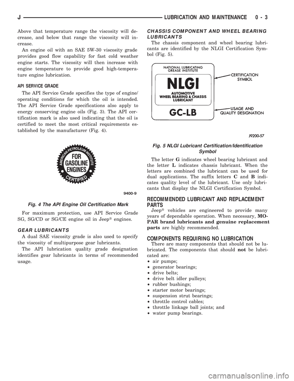
energy conserving engine oils (Fig. 3). The API cer-
tification mark is also used indicating that the oil is
certified to meet the most critical requirements es-
tablished by the manufacturer (Fig. 4).
For maximum protection, use API Service Grade
SG, SG/CD or SG/CE engine oil in Jeeptengines.
GEAR LUBRICANTS
A dual SAE viscosity grade is also used to specify
the viscosity of multipurpose gear lubricants.
The API lubrication quality grade designation
identifies gear lubricants in terms of recommended
usage.
CHASSIS COMPONENT AND WHEEL BEARING
LUBRICANTS
The chassis component and wheel bearing lubri-
cants are identified by the NLGI Certification Sym-
bol (Fig. 5).
The letterGindicates wheel bearing lubricant and
the letterLindicates chassis lubricant. When the
letters are combined the lubricant can be used for
dual applications. The suffix lettersCandBindi-
cates quality level of the lubricant. Use only lubri-
cants that display the NLGI Certification Symbol.
RECOMMENDED LUBRICANT AND REPLACEMENT
PARTS
Jeeptvehicles are engineered to provide many
years of dependable operation. When necessary,MO-
PAR brand lubricants and genuine replacement
partsare highly recommended.
COMPONENTS REQUIRING NO LUBRICATION
There are many components that should not be lu-
bricated. The components that shouldnotbe lubri-
cated are:
²air pumps;
²generator bearings;
²drive belts;
²drive belt idler pulleys;
²rubber bushings;
²starter motor bearings;
²suspension strut bearings;
²throttle control cables;
²throttle linkage ball joints; and
²water pump bearings.
Fig. 4 The API Engine Oil Certification Mark
Fig. 5 NLGI Lubricant Certification/Identification
Symbol
JLUBRICATION AND MAINTENANCE 0 - 3
Page 43 of 1784
not change except when a spindle or ball stud is
damaged or bent. The angle is not adjustable and the
damaged component(s) must be replaced to correct
mis-alignment.
CAUTION:Do not attempt to modify any suspension
or steering component by heating and bending.
PRE-ALIGNMENT INSPECTION
Before starting a front wheel alignment, the follow-
ing inspection and necessary corrections must be
completed.
(1) Tires with the same recommended air pressure,
size, and thread wear. Refer to Group 22, Tires And
Wheels for diagnosis information.
(2) Front wheel bearings for wear.
(3) Ball studs, steering linkage pivot points and
steering gear for looseness, roughness, binding or
wear. Refer to Group 19, Steering for additional in-
formation.
(4) Front wheels for excessive radial or lateral
runout and unbalance. Refer to Group 22, Tires And
Wheels for diagnosis information.
(5) Suspension components for wear and noise.
Check components for correct torque. Refer to Groups
2 and 3, Suspension and Axle for additional informa-
tion.
ALIGNMENT MEASUREMENTS AND ADJUSTMENTS
Before each alignment reading, the vehicle should
be jounced (rear first, then front). Grasp each bumper
at the center and jounce the vehicle up and down
several times. Always release the bumper in the
down position.Set the front end alignment to
specifications with the vehicle at its NOR-
MALLY RIDE HEIGHT.
CAMBER
The wheel camber angle (Fig. 1) is preset at ZERO
DEGREES (0É). The angle is not adjustable and can-
not be altered.
CASTER
The caster angle (Fig. 1) is set at:
²XJ manual transmission, POSITIVE 6.5 DE-
GREES (+6.5É).
²XJ automatic transmission, POSITIVE 8.0 DE-
GREES (+8.0É).
²YJ all transmissions, POSITIVE 6.0 DEGREES
(+6.0É).
Before checking the caster of the front axle for cor-
rect angle. Be sure the axle is not bent or twisted.
Road test the vehicle, and make left and right
turns. If the steering wheel returns to the center po-
sition unassisted, the caster angle is correct. How-ever, if steering wheel does not return toward the
center position unassisted, an incorrect caster angle
is probable.
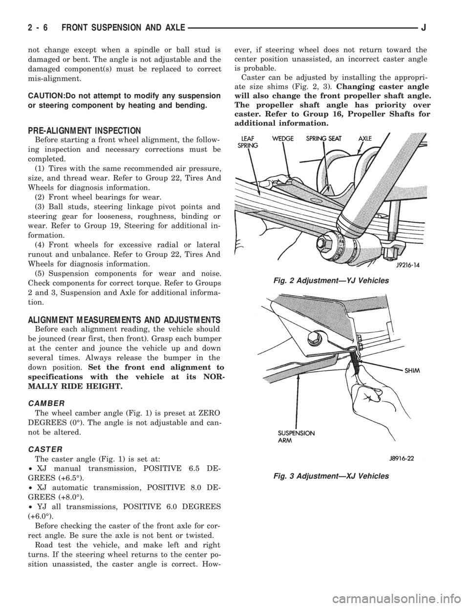
Caster can be adjusted by installing the appropri-
ate size shims (Fig. 2, 3).Changing caster angle
will also change the front propeller shaft angle.
The propeller shaft angle has priority over
caster. Refer to Group 16, Propeller Shafts for
additional information.
Fig. 2 AdjustmentÐYJ Vehicles
Fig. 3 AdjustmentÐXJ Vehicles
2 - 6 FRONT SUSPENSION AND AXLEJ
Page 49 of 1784
(2) Install the bolts and finger tighten the nuts
(Fig. 3).
(3) Remove support and lower the vehicle.
(4) Tighten the front and rear nuts to 115 Nzm (85
ft. lbs.) torque.
SPRING AND SHOCK DIAGNOSIS
A squeak noise from the shock absorber can be pro-
duced if movement between the rubber bushings and
the metal occurs. This noise can usually be stopped
by tightening the attaching nuts. If the squeak noisepersists, inspect for damaged and worn bushings, and
attaching components. Repair as necessary.
The shock absorber bushings do not require any
type of lubrication. Do not lubricate the bushings to
reduce bushing noise. Grease or mineral oil-base lu-
bricants will deteriorate the bushing rubber.
The shock absorbers are not refillable or adjust-
able. If a malfunction occurs, the shock absorber
must be replaced. To test a shock absorber, hold it in
an upright position and force the piston into and out
of the cylinder four or five times. The action through-
out each stroke should be smooth and even.
SHOCK ABSORBER
REMOVAL
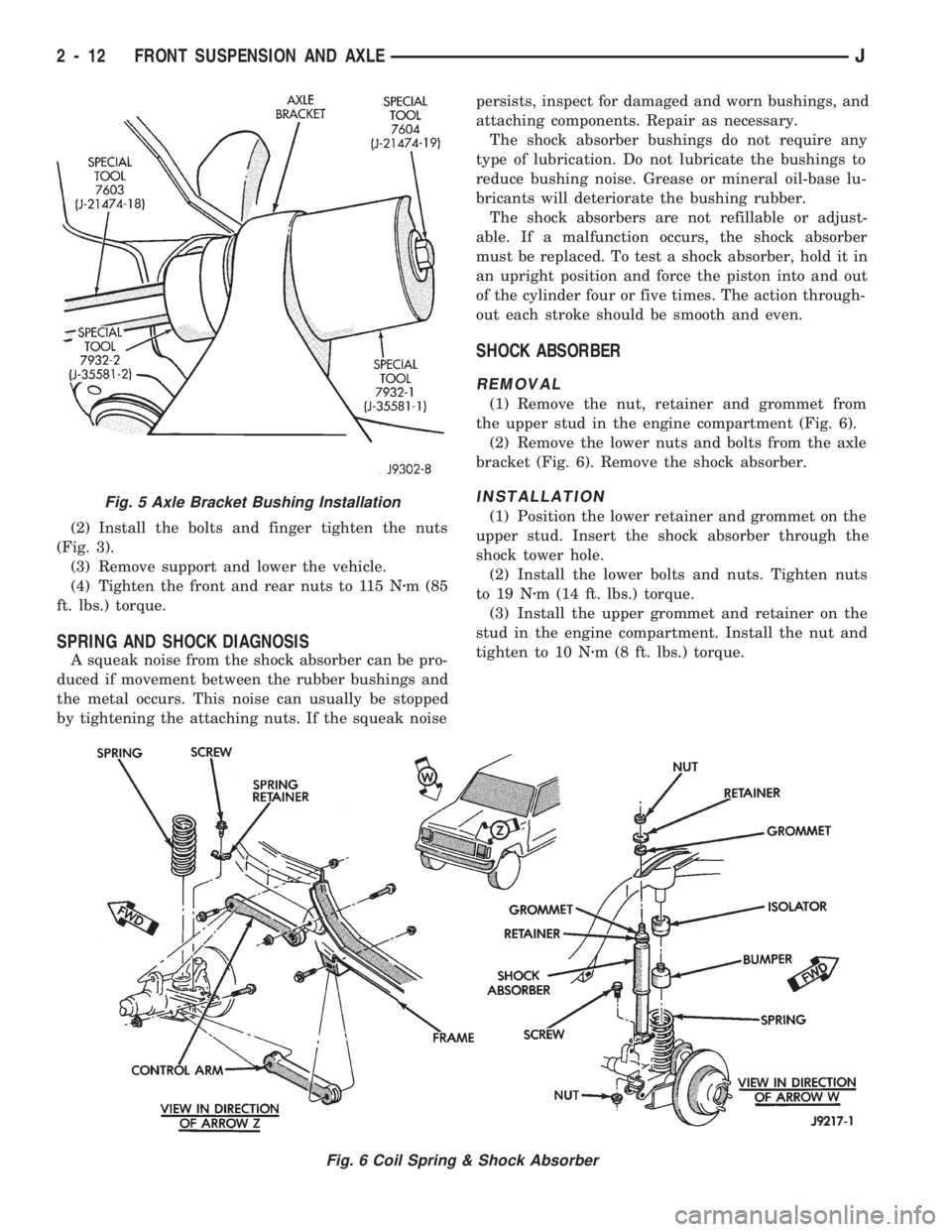
(1) Remove the nut, retainer and grommet from
the upper stud in the engine compartment (Fig. 6).
(2) Remove the lower nuts and bolts from the axle
bracket (Fig. 6). Remove the shock absorber.
INSTALLATION
(1) Position the lower retainer and grommet on the
upper stud. Insert the shock absorber through the
shock tower hole.
(2) Install the lower bolts and nuts. Tighten nuts
to 19 Nzm (14 ft. lbs.) torque.
(3) Install the upper grommet and retainer on the
stud in the engine compartment. Install the nut and
tighten to 10 Nzm (8 ft. lbs.) torque.
Fig. 6 Coil Spring & Shock Absorber
Fig. 5 Axle Bracket Bushing Installation
2 - 12 FRONT SUSPENSION AND AXLEJ
Page 51 of 1784
STABILIZER BAR
REMOVAL
(1) Raise and support the vehicle.
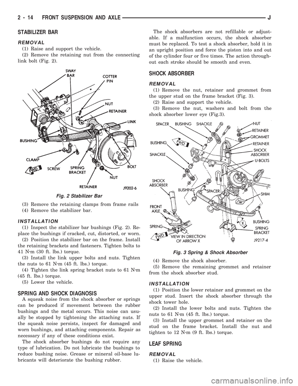
(2) Remove the retaining nut from the connecting
link bolt (Fig. 2).
(3) Remove the retaining clamps from frame rails
(4) Remove the stabilizer bar.
INSTALLATION
(1) Inspect the stabilizer bar bushings (Fig. 2). Re-
place the bushings if cracked, cut, distorted, or worn.
(2) Position the stabilizer bar on the frame. Install
the retaining brackets and fasteners. Tighten bolts to
41 Nzm (30 ft. lbs.) torque.
(3) Install the link upper bolts and nuts. Tighten
the nuts to 61 Nzm (45 ft. lbs.) torque.
(4) Tighten the link spring bracket nuts to 61 Nzm
(45 ft. lbs.) torque.
(5) Lower the vehicle.
SPRING AND SHOCK DIAGNOSIS
A squeak noise from the shock absorber or springs
can be produced if movement between the rubber
bushings and the metal occurs. This noise can usu-
ally be stopped by tightening the attaching nuts. If
the squeak noise persists, inspect for damaged and
worn bushings, and attaching components. Repair as
necessary if any of these conditions exist.
The shock absorber bushings do not require any
type of lubrication. Do not lubricate the bushings to
reduce bushing noise. Grease or mineral oil-base lu-
bricants will deteriorate the bushing rubber.The shock absorbers are not refillable or adjust-
able. If a malfunction occurs, the shock absorber
must be replaced. To test a shock absorber, hold it in
an upright position and force the piston into and out
of the cylinder four or five times. The action through-
out each stroke should be smooth and even.
SHOCK ABSORBER
REMOVAL
(1) Remove the nut, retainer and grommet from
the upper stud on the frame bracket (Fig. 3).
(2) Raise and support the vehicle.
(3) Remove the nut, washers and bolt from the
shock absorber lower eye (Fig.3).
(4) Remove the shock absorber.
(5) Remove the remaining grommet and retainer
from the shock absorber stud.
INSTALLATION
(1) Position the lower retainer and grommet on the
upper stud. Insert the shock absorber through the
shock tower hole.
(2) Install the lower bolts and nuts. Tighten the
nuts to 61 Nzm (45 ft. lbs.) torque.
(3) Install the upper grommet and retainer on the
stud on the frame bracket. Install the nut and
tighten to 12 Nzm (9 ft. lbs.) torque.
LEAF SPRING
REMOVAL
(1) Raise the vehicle.
Fig. 2 Stabilizer Bar
Fig. 3 Spring & Shock Absorber
2 - 14 FRONT SUSPENSION AND AXLEJ
Page 53 of 1784
AXLE NOISE/VIBRATION DIAGNOSIS
INDEX
page page
Driveline Snap........................... 17
Gear and Bearing Noise................... 16
General Information....................... 16Low Speed Knock........................ 17
Vibration............................... 17
GENERAL INFORMATION
Axle bearing problem conditions are usually caused
by:
²Insufficient or incorrect lubricant
²Foreign matter/water contamination
²Incorrect bearing preload torque adjustment
²Incorrect backlash (to tight)
When serviced, the bearings must be cleaned thor-
oughly. They should be dried with lint-free shop tow-
els.Never dry bearings with compressed air.
This will overheat them and brinell the bearing
surfaces. This will result in noisy operation after
repair.
Axle gear problem conditions are usually the result
of:
²Insufficient lubrication
²Incorrect or contaminated lubricant
²Overloading (excessive engine torque) or exceeding
vehicle weight capacity
²Incorrect clearance or backlash adjustment
Insufficient lubrication is usually the result of a
housing cover leak. It can also be from worn axle
shaft or pinion gear seals. Check for cracks or porous
areas in the housing or tubes.
Using the wrong lubricant will cause overheating
and gear failure. Gear tooth cracking and bearing
spalling are indicators of this.
Axle component breakage is most often the result
of:
²Severe overloading
²Insufficient lubricant
²Incorrect lubricant
²Improperly tightened components
Overloading occurs when towing heavier than rec-
ommended loads. Component breakage can occur
when the wheels are spun excessively. Incorrect lu-
bricant quantity contributes to breakage. Loose dif-
ferential components can also cause breakage.
Incorrect bearing preload or gear backlash will not
result in component breakage. Mis-adjustment will
produce enough noise to cause service repair before a
failure occurs. If a mis-adjustment condition is not
corrected, component failure can result.
Excessive bearing preload may not be noisy. This
condition will cause high temperature which can re-
sult in bearing failure.
GEAR AND BEARING NOISE
GEAR NOISE
Axle gear noise can be caused by insufficient lubri-
cant. Incorrect backlash, tooth contact, or worn/dam-
aged gears can cause noise.
Gear noise usually happens at a specific speed
range. The range is 30 to 40 mph, or above 50 mph.
The noise can also occur during a specific type of
driving condition. These conditions are acceleration,
deceleration, coast, or constant load.
When road testing, accelerate the vehicle to the
speed range where the noise is the greatest. Shift
out-of-gear and coast through the peak-noise range.
If the noise stops or changes greatly, check for insuf-
ficient lubricant. Incorrect ring gear backlash, or
gear damage can cause noise changes.
Differential side and pinion gears can be checked
by turning the vehicle. They usually do not cause
noise in straight-ahead driving. These gears are
loaded during vehicle turns. If noise does occur dur-
ing vehicle turns, the side or pinion gears could be
worn or damaged. A worn pinion gear mate shaft can
also cause a snapping or a knocking noise.
BEARING NOISE
The axle shaft, differential and pinion gear bear-
ings can all produce noise when worn or damaged.
Bearing noise can be either a whining, or a growling
sound.
Pinion gear bearings have a constant-pitch noise.
This noise changes only with vehicle speed. Pinion
bearing noise will be higher because it rotates at a
faster rate. Drive the vehicle and load the differen-
tial. If bearing noise occurs the pinion rear bearing is
the source of the noise. If the bearing noise is heard
during a coast, front bearing is the source.
Worn, damaged differential bearings usually pro-
duce a low pitch noise. Differential bearing noise is
similar to pinion bearing. The pitch of differential
bearing noise is also constant and varies only with
vehicle speed.
Axle shaft bearings produce noise and vibration
when worn or damaged. The noise generally changes
when the bearings are loaded. Road test the vehicle.
Turn the vehicle sharply to the left and to the right.
This will load the bearings and change the noise
2 - 16 FRONT SUSPENSION AND AXLEJ
Page 54 of 1784
level. Where axle bearing damage is slight, the noise
is usually not noticeable at speeds above 30 mph.
LOW SPEED KNOCK
Low speed knock is generally caused by a worn
U-joint or by worn side-gear thrust washers. A worn
pinion gear shaft bore will also cause low speed
knock.
VIBRATION
Vibration at the rear of the vehicle is usually
caused by a:
²Damaged drive shaft
²Missing drive shaft balance weight
²Worn, out-of-balance wheels
²Loose wheel lug nuts
²Worn U-joint
²Loose spring U-bolts
²Loose/broken springs
²Damaged axle shaft bearings
²Loose pinion gear nut
²Excessive pinion yoke run out
²Bent axle shaft
Check for loose or damaged front-end components
or engine/transmission mounts. These componentscan contribute to what appears to be a rear-end vi-
bration. Do not overlook engine accessories, brackets
and drive belts.
All driveline components should be examined be-
fore starting any repair.
Refer to Group 22ÐTires And Wheels for addi-
tional information involving vibration diagnosis.
DRIVELINE SNAP
A snap or clunk noise when the vehicle is shifted
into gear (or the clutch engaged), can be caused by:
²High engine idle speed
²Loose engine/transmission/transfer case mounts
²Worn U-joints
²Loose spring mounts
²Loose pinion gear nut and yoke
²Excessive ring gear backlash
²Excessive differential side gear-to-case clearance
The source of a snap or a clunk noise can be deter-
mined with the assistance of a helper. Raise the ve-
hicle on a hoist with the wheels free to rotate.
Instruct the helper to shift the transmission into
gear. Listen for the noise, a mechanics stethoscope is
helpful in isolating the source of a noise.
JFRONT SUSPENSION AND AXLE 2 - 17
Page 63 of 1784
(3) Place the socket (driver) against one bearing
cap. Position the yoke with the socket wrench in a
vise.
(4) Compress the vise to force the bearing caps into
the yoke. Force the caps enough to install the retain-
ing clips.
(5) Install the bearing cap retaining clips.
(6) Install the axle shaft, refer to Hub Bearing and
Axle Shaft installation.
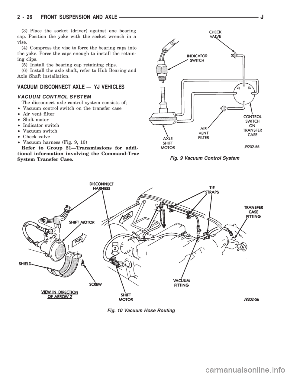
VACUUM DISCONNECT AXLE Ð YJ VEHICLES
VACUUM CONTROL SYSTEM
The disconnect axle control system consists of;
²Vacuum control switch on the transfer case
²Air vent filter
²Shift motor
²Indicator switch
²Vacuum switch
²Check valve
²Vacuum harness (Fig. 9, 10)
Refer to Group 21ÐTransmissions for addi-
tional information involving the Command-Trac
System Transfer Case.
Fig. 9 Vacuum Control System
Fig. 10 Vacuum Hose Routing
2 - 26 FRONT SUSPENSION AND AXLEJ
Page 72 of 1784
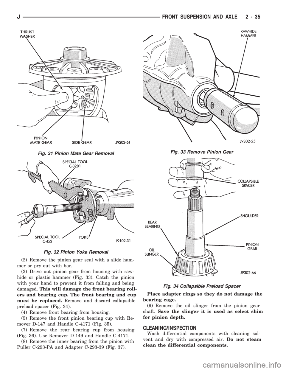
(2) Remove the pinion gear seal with a slide ham-
mer or pry out with bar.
(3) Drive out pinion gear from housing with raw-
hide or plastic hammer (Fig. 33). Catch the pinion
with your hand to prevent it from falling and being
damaged.This will damage the front bearing roll-
ers and bearing cup. The front bearing and cup
must be replaced.Remove and discard collapsible
preload spacer (Fig. 34).
(4) Remove front bearing from housing.
(5) Remove the front pinion bearing cup with Re-
mover D-147 and Handle C-4171 (Fig. 35).
(7) Remove the rear bearing cup from housing
(Fig. 36). Use Remover D-149 and Handle C-4171.
(8) Remove the inner bearing from the pinion with
Puller C-293-PA and Adapter C-293-39 (Fig. 37).Place adapter rings so they do not damage the
bearing cage.
(9) Remove the oil slinger from the pinion gear
shaft.Save the slinger it is used as select shim
for pinion depth.
CLEANING/INSPECTION
Wash differential components with cleaning sol-
vent and dry with compressed air.Do not steam
clean the differential components.
Fig. 31 Pinion Mate Gear Removal
Fig. 32 Pinion Yoke Removal
Fig. 33 Remove Pinion Gear
Fig. 34 Collapsible Preload Spacer
JFRONT SUSPENSION AND AXLE 2 - 35