1994 JEEP CHEROKEE radiator cap
[x] Cancel search: radiator capPage 901 of 1784
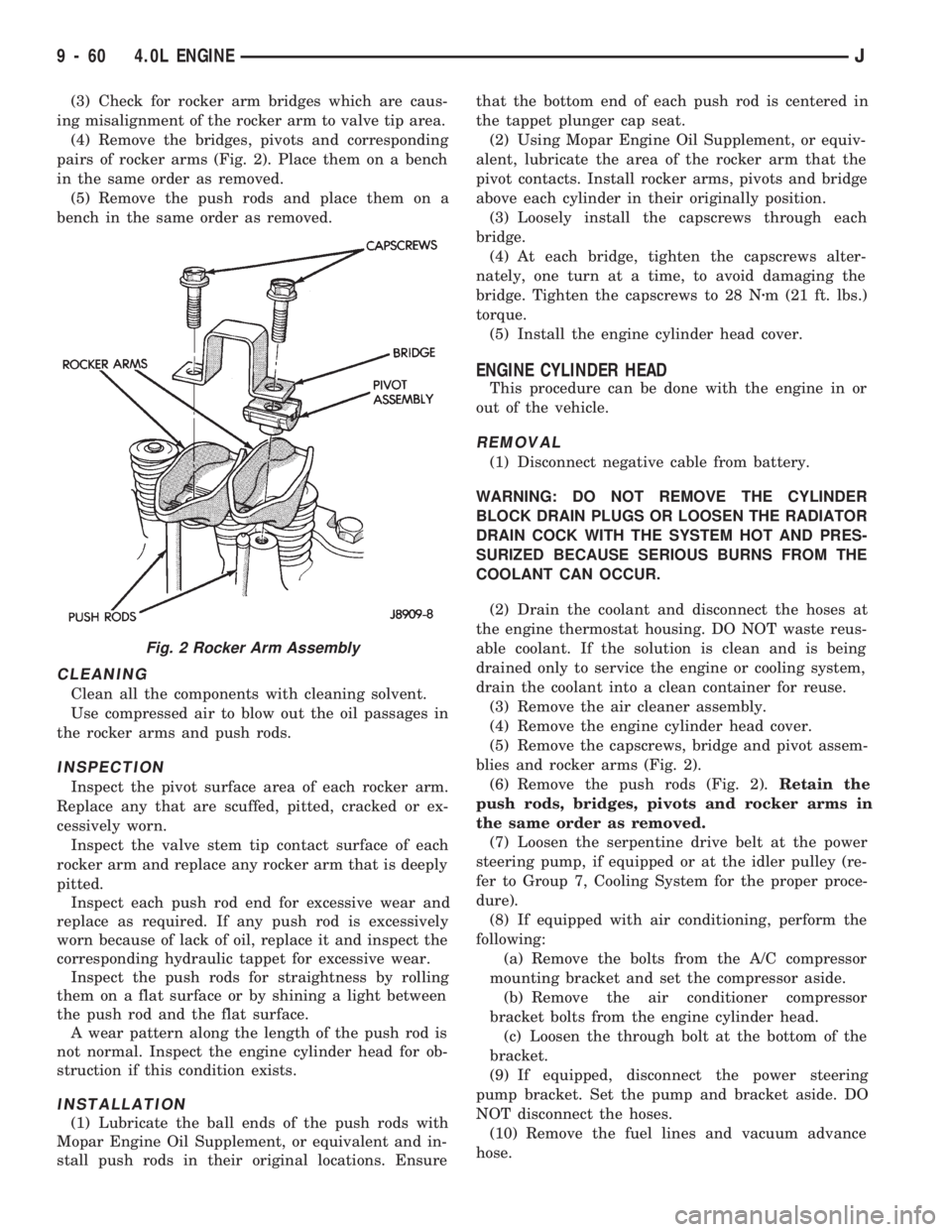
(3) Check for rocker arm bridges which are caus-
ing misalignment of the rocker arm to valve tip area.
(4) Remove the bridges, pivots and corresponding
pairs of rocker arms (Fig. 2). Place them on a bench
in the same order as removed.
(5) Remove the push rods and place them on a
bench in the same order as removed.
CLEANING
Clean all the components with cleaning solvent.
Use compressed air to blow out the oil passages in
the rocker arms and push rods.
INSPECTION
Inspect the pivot surface area of each rocker arm.
Replace any that are scuffed, pitted, cracked or ex-
cessively worn.
Inspect the valve stem tip contact surface of each
rocker arm and replace any rocker arm that is deeply
pitted.
Inspect each push rod end for excessive wear and
replace as required. If any push rod is excessively
worn because of lack of oil, replace it and inspect the
corresponding hydraulic tappet for excessive wear.
Inspect the push rods for straightness by rolling
them on a flat surface or by shining a light between
the push rod and the flat surface.
A wear pattern along the length of the push rod is
not normal. Inspect the engine cylinder head for ob-
struction if this condition exists.
INSTALLATION
(1) Lubricate the ball ends of the push rods with
Mopar Engine Oil Supplement, or equivalent and in-
stall push rods in their original locations. Ensurethat the bottom end of each push rod is centered in
the tappet plunger cap seat.
(2) Using Mopar Engine Oil Supplement, or equiv-
alent, lubricate the area of the rocker arm that the
pivot contacts. Install rocker arms, pivots and bridge
above each cylinder in their originally position.
(3) Loosely install the capscrews through each
bridge.
(4) At each bridge, tighten the capscrews alter-
nately, one turn at a time, to avoid damaging the
bridge. Tighten the capscrews to 28 Nzm (21 ft. lbs.)
torque.
(5) Install the engine cylinder head cover.
ENGINE CYLINDER HEAD
This procedure can be done with the engine in or
out of the vehicle.
REMOVAL
(1) Disconnect negative cable from battery.
WARNING: DO NOT REMOVE THE CYLINDER
BLOCK DRAIN PLUGS OR LOOSEN THE RADIATOR
DRAIN COCK WITH THE SYSTEM HOT AND PRES-
SURIZED BECAUSE SERIOUS BURNS FROM THE
COOLANT CAN OCCUR.
(2) Drain the coolant and disconnect the hoses at
the engine thermostat housing. DO NOT waste reus-
able coolant. If the solution is clean and is being
drained only to service the engine or cooling system,
drain the coolant into a clean container for reuse.
(3) Remove the air cleaner assembly.
(4) Remove the engine cylinder head cover.
(5) Remove the capscrews, bridge and pivot assem-
blies and rocker arms (Fig. 2).
(6) Remove the push rods (Fig. 2).Retain the
push rods, bridges, pivots and rocker arms in
the same order as removed.
(7) Loosen the serpentine drive belt at the power
steering pump, if equipped or at the idler pulley (re-
fer to Group 7, Cooling System for the proper proce-
dure).
(8) If equipped with air conditioning, perform the
following:
(a) Remove the bolts from the A/C compressor
mounting bracket and set the compressor aside.
(b) Remove the air conditioner compressor
bracket bolts from the engine cylinder head.
(c) Loosen the through bolt at the bottom of the
bracket.
(9) If equipped, disconnect the power steering
pump bracket. Set the pump and bracket aside. DO
NOT disconnect the hoses.
(10) Remove the fuel lines and vacuum advance
hose.
Fig. 2 Rocker Arm Assembly
9 - 60 4.0L ENGINEJ
Page 903 of 1784
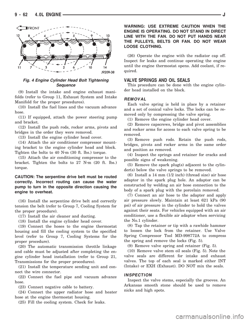
(9) Install the intake and engine exhaust mani-
folds (refer to Group 11, Exhaust System and Intake
Manifold for the proper procedures).
(10) Install the fuel lines and the vacuum advance
hose.
(11) If equipped, attach the power steering pump
and bracket.
(12) Install the push rods, rocker arms, pivots and
bridges in the order they were removed.
(13) Install the engine cylinder head cover.
(14) Attach the air conditioner compressor mount-
ing bracket to the engine cylinder head and block.
Tighten the bolts to 40 Nzm (30 ft. lbs.) torque.
(15) Attach the air conditioning compressor to the
bracket. Tighten the bolts to 27 Nzm (20 ft. lbs.)
torque.
CAUTION: The serpentine drive belt must be routed
correctly. Incorrect routing can cause the water
pump to turn in the opposite direction causing the
engine to overheat.
(16) Install the serpentine drive belt and correctly
tension the belt (refer to Group 7, Cooling System for
the proper procedure).
(17) Install the air cleaner and ducting.
(18) Install the engine cylinder head cover.
(19) Connect the hoses to the engine thermostat
housing and fill the cooling system to the specified
level (refer to Group 7, Cooling Systems for the
proper procedure).
(20) The automatic transmission throttle linkage
and cable must be adjusted after completing the en-
gine cylinder head installation (refer to Group 21,
Transmissions for the proper procedures).
(21) Install the temperature sending unit and con-
nect the wire connector.
(22) Connect the fuel pipe and vacuum advance
hose.
(23) Connect negative cable to battery.
(24) Connect the upper radiator hose and heater
hose at the engine thermostat housing.
(25) Fill the cooling system. Check for leaks.WARNING: USE EXTREME CAUTION WHEN THE
ENGINE IS OPERATING. DO NOT STAND IN DIRECT
LINE WITH THE FAN. DO NOT PUT HANDS NEAR
THE PULLEYS, BELTS OR FAN. DO NOT WEAR
LOOSE CLOTHING.
(26) Operate the engine with the radiator cap off.
Inspect for leaks and continue operating the engine
until the engine thermostat opens. Add coolant, if re-
quired.
VALVE SPRINGS AND OIL SEALS
This procedure can be done with the engine cylin-
der head installed on the block.
REMOVAL
Each valve spring is held in place by a retainer
and a set of conical valve locks. The locks can be re-
moved only by compressing the valve spring.
(1) Remove the engine cylinder head cover.
(2) Remove capscrews, bridge and pivot assemblies
and rocker arms for access to each valve spring to be
removed.
(3) Remove push rods. Retain the push rods,
bridges, pivots and rocker arms in the same order
and position as removed.
(4) Inspect the springs and retainer for cracks and
possible signs of weakening.
(5) Remove the spark plug(s) adjacent to the cylin-
der(s) below the valve springs to be removed.
(6) Install a 14 mm (1/2 inch) (thread size) air hose
adaptor in the spark plug hole. An adaptor can be
constructed by welding an air hose connection to the
body of a spark plug with the porcelain removed.
(7) Connect an air hose to the adapter and apply
air pressure slowly. Maintain at least 621 kPa (90
psi) of air pressure in the cylinder to hold the valves
against their seats. For vehicles equipped with an air
conditioner, use a flexible air adaptor when servicing
the No.1 cylinder.
(8) Tap the retainer or tip with a rawhide hammer
to loosen the lock from the retainer. Use Valve
Spring Compressor Tool MD-998772A to compress
the spring and remove the locks (Fig. 5).
(9) Remove valve spring and retainer (Fig. 5).
(10) Remove valve stem oil seals (Fig. 5). Note the
valve seals are different for intake and exhaust
valves. The top of each seal is marked either INT
(Intake) or EXH (Exhaust). DO NOT mix the seals.
INSPECTION
Inspect the valve stems, especially the grooves. An
Arkansas smooth stone should be used to remove
nicks and high spots.
Fig. 4 Engine Cylinder Head Bolt Tightening
Sequence
9 - 62 4.0L ENGINEJ
Page 910 of 1784
12.7 mm (1/2 inch) replace it. The correct timing
chain has 48 pins. A chain with more than 48 pins
will cause excessive slack.
INSTALLATION
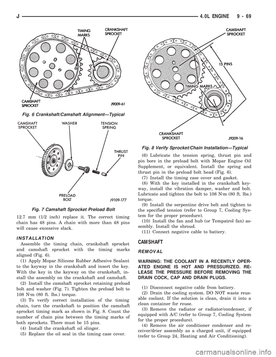
Assemble the timing chain, crankshaft sprocket
and camshaft sprocket with the timing marks
aligned (Fig. 6).
(1) Apply Mopar Silicone Rubber Adhesive Sealant
to the keyway in the crankshaft and insert the key.
With the key in the keyway on the crankshaft, in-
stall the assembly on the crankshaft and camshaft.
(2) Install the camshaft sprocket retaining preload
bolt and washer (Fig. 7). Tighten the preload bolt to
108 Nzm (80 ft. lbs.) torque.
(3) To verify correct installation of the timing
chain, turn the crankshaft to position the camshaft
sprocket timing mark as shown in Fig. 8. Count the
number of chain pins between the timing marks of
both sprockets. There must be 15 pins.
(4) Install the crankshaft oil slinger.
(5) Replace the oil seal in the timing case cover.(6) Lubricate the tension spring, thrust pin and
pin bore in the preload bolt with Mopar Engine Oil
Supplement, or equivalent. Install the spring and
thrust pin in the preload bolt head (Fig. 6).
(7) Install the timing case cover and gasket.
(8) With the key installed in the crankshaft key-
way, install the vibration damper, washer and bolt.
Lubricate and tighten the bolt to 108 Nzm (80 ft. lbs.)
torque.
(9) Install the serpentine drive belt and tighten to
the specified tension (refer to Group 7, Cooling Sys-
tem for the proper procedure).
(10) Install the fan and hub (or Tempatrol fan) as-
sembly. Install the shroud.
(11) Connect negative cable to battery.CAMSHAFT
REMOVAL
WARNING: THE COOLANT IN A RECENTLY OPER-
ATED ENGINE IS HOT AND PRESSURIZED. RE-
LEASE THE PRESSURE BEFORE REMOVING THE
DRAIN COCK, CAP AND DRAIN PLUGS.
(1) Disconnect negative cable from battery.
(2) Drain the cooling system. DO NOT waste reus-
able coolant. If the solution is clean, drain it into a
clean container for reuse.
(3) Remove the radiator or radiator/condenser, if
equipped with A/C (refer to Group 7, Cooling System
for the proper procedure).
(4) Remove the air conditioner condenser and re-
ceiver/drier assembly as a charged unit, if equipped
(refer to Group 24, Heating and Air Conditioning).
Fig. 6 Crankshaft/Camshaft AlignmentÐTypical
Fig. 7 Camshaft Sprocket Preload Bolt
Fig. 8 Verify Sprocket/Chain InstallationÐTypical
J4.0L ENGINE 9 - 69
Page 911 of 1784

(5) Remove the distributor cap and mark the posi-
tion of the rotor.
(6) Remove the distributor and ignition wires.
(7) Remove the engine cylinder head cover.
(8) Remove the rocker arms, bridges and pivots.
(9) Remove the push rods.
(10) Remove the engine cylinder head and gasket.
(11) Remove the hydraulic valve tappets from the
engine cylinder head.
(12) Remove the vibration damper.
(13) Remove the timing case cover.
(14) Remove the timing chain and sprockets.
(15) Remove the front bumper and/or grille, as re-
quired.
(16) Remove the camshaft (Fig. 9).
INSPECTION
Inspect the cam lobes for wear.
Inspect the bearing journals for uneven wear pat-
tern or finish.
Inspect the bearings for wear.
Inspect the distributor drive gear for wear.
If the camshaft appears to have been rubbing
against the timing case cover, examine the oil pres-
sure relief holes in the rear cam journal. The oil
pressure relief holes must be free of debris.
INSTALLATION
(1) Lubricate the camshaft with Mopar Engine Oil
Supplement, or equivalent.
(2) Carefully install the camshaft to prevent dam-
age to the camshaft bearings (Fig. 9).
(3) Install the timing chain, crankshaft sprocket
and camshaft sprocket with the timing marks
aligned.
(4) Install the camshaft sprocket retaining preload
bolt. Tighten the bolt to 108 Nzm (80 ft. lbs.) torque.
(5) Lubricate the tension spring, the thrust pin
and the pin bore in the preload bolt with Mopar En-
gine Oil Supplement, or equivalent. Install the
spring and thrust pin in the preload bolt head.(6) Install the timing case cover with a replace-
ment oil seal (Fig. 10). Refer to Timing Case Cover
Installation.
(7) Install the vibration damper (Fig. 10).
(8) Install the hydraulic valve tappets.
(9) Install the engine cylinder head.
(10) Install the push rods.
(11) Install the rocker arms and pivot and bridge
assemblies. Tighten each of the capscrews for each
bridge alternately, one turn at a time, to avoid dam-
aging the bridge.
(12) Install the engine cylinder head cover.
(13) Install the serpentine drive belt and tighten to
the specified tension (refer to Group 7, Cooling Sys-
tem for the proper procedure).
(14) Rotate the crankshaft until the No.1 piston is
at the TDC position on the compression stroke.
(15) Install the distributor, cap and ignition wires.
Install the distributor so that the rotor is aligned
with the mark made during removal. The rotor
should be aligned with the No.1 cylinder spark plug
terminal on the cap when the distributor housing is
fully seated on the cylinder block.
During installation, lubricate the hydraulic
valve tappets and all valve components with Mo-
par Engine Oil Supplement, or equivalent. The
Mopar Engine Oil Supplement, or equivalent
must remain with the engine oil for at least 1 609
km (1,000 miles). The oil supplement need not be
drained until the next scheduled oil change.
(16) Install the A/C condenser and receiver/drier
assembly, if equipped (refer to Group 24, Heating
and Air Conditioning).
CAUTION: Both service valves must be opened be-
fore the air conditioning system is operated.
(17) Install the radiator, connect the hoses and fill
the cooling system to the specified level (refer to
Group 7, Cooling System for the proper procedure).
Fig. 9 Camshaft
Fig. 10 Timing Case Cover Components
9 - 70 4.0L ENGINEJ
Page 939 of 1784
INTAKE MANIFOLDÐ2.5L ENGINE
REMOVAL
(1) Disconnect the battery negative cable.
(2) Remove the air inlet hose from the throttle
body and air cleaner.
(3) Loosen the accessory drive belt tension and re-
move the belt from the power steering pump.
(4) Remove the power steering pump and brackets
from the water pump and intake manifold. Support
power steering pump and bracket with mechanics
wire attached to the radiator upper crossmember.
(5) Remove the fuel tank filler cap to relieve the
fuel tank pressure.
(6) Install the fuel tank filler cap.
(7) Disconnect fuel supply and return tube from
the fuel rail (refer to Group 14, Fuel System - Quick
Connect Fittings).
(8) Disconnect the accelerator cable from the throt-
tle body and the holddown bracket.
CAUTION: When disconnecting the cruise control
connector at the throttle body, DO NOT pry the con-
nector off with pliers or screwdriver. Use finger
pressure only. Prying the connector off could break
it.
(9) Disconnect the electrical connectors. Pull the
harnesses away from the manifold.
²The throttle position sensor.
²The idle speed control motor.
²The coolant temperature sensor at the thermostat.
²The manifold air temperature sensor at the intake
manifold.
²The fuel injectors.
²The oxygen sensor.
(10) Disconnect the crankcase ventilation (CCV)
vacuum hose and manifold absolute pressure (MAP)
sensor vacuum hose connector at the intake mani-
fold.
(11) Disconnect vacuum hose from vacuum port on
the intake manifold.
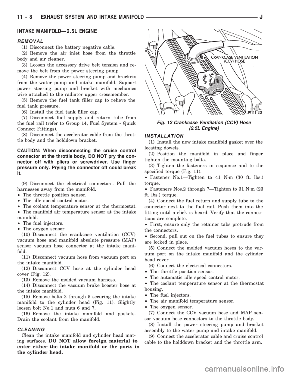
(12) Disconnect CCV hose at the cylinder head
cover (Fig. 12).
(13) Remove the molded vacuum harness.
(14) Disconnect the vacuum brake booster hose at
the intake manifold.
(15) Remove bolts 2 through 5 securing the intake
manifold to the cylinder head (Fig. 11). Slightly
loosen bolt No.1 and nuts 6 and 7.
(16) Remove the intake manifold and gaskets.
Drain the coolant from the manifold.
CLEANING
Clean the intake manifold and cylinder head mat-
ing surfaces.DO NOT allow foreign material to
enter either the intake manifold or the ports in
the cylinder head.
INSTALLATION
(1) Install the new intake manifold gasket over the
locating dowels.
(2) Position the manifold in place and finger
tighten the mounting bolts.
(3) Tighten the fasteners in sequence and to the
specified torque (Fig. 11).
²Fastener No.1ÐTighten to 41 Nzm (30 ft. lbs.)
torque.
²Fasteners Nos.2 through 7ÐTighten to 31 Nzm (23
ft. lbs.) torque.
(4) Connect the fuel return and supply tube to the
connector next to the fuel rail. Push them into the
fitting until a click is heard. Verify that the connec-
tions are complete.
²First, ensure only the retainer tabs protrude from
the connectors.
²Second, pull out on the fuel tubes to ensure they
are locked in place.
(5) Connect the molded vacuum hoses to the vac-
uum port on the intake manifold and the cylinder
head cover.
(6) Connect the electrical connectors.
²The throttle position sensor.
²The automatic idle speed control motor.
²The coolant temperature sensor at the thermostat
housing.
²The fuel injectors.
²The air manifold temperature sensor.
²The oxygen sensor.
(7) Connect the CCV vacuum hose and MAP sen-
sor vacuum hose connectors to the throttle body.
(8) Install the power steering pump and bracket
assembly to the water pump and intake manifold.
(9) Connect the accelerator cable and cruise control
cable to the holddown bracket and the throttle arm.
Fig. 12 Crankcase Ventilation (CCV) Hose
(2.5L Engine)
11 - 8 EXHAUST SYSTEM AND INTAKE MANIFOLDJ
Page 1591 of 1784
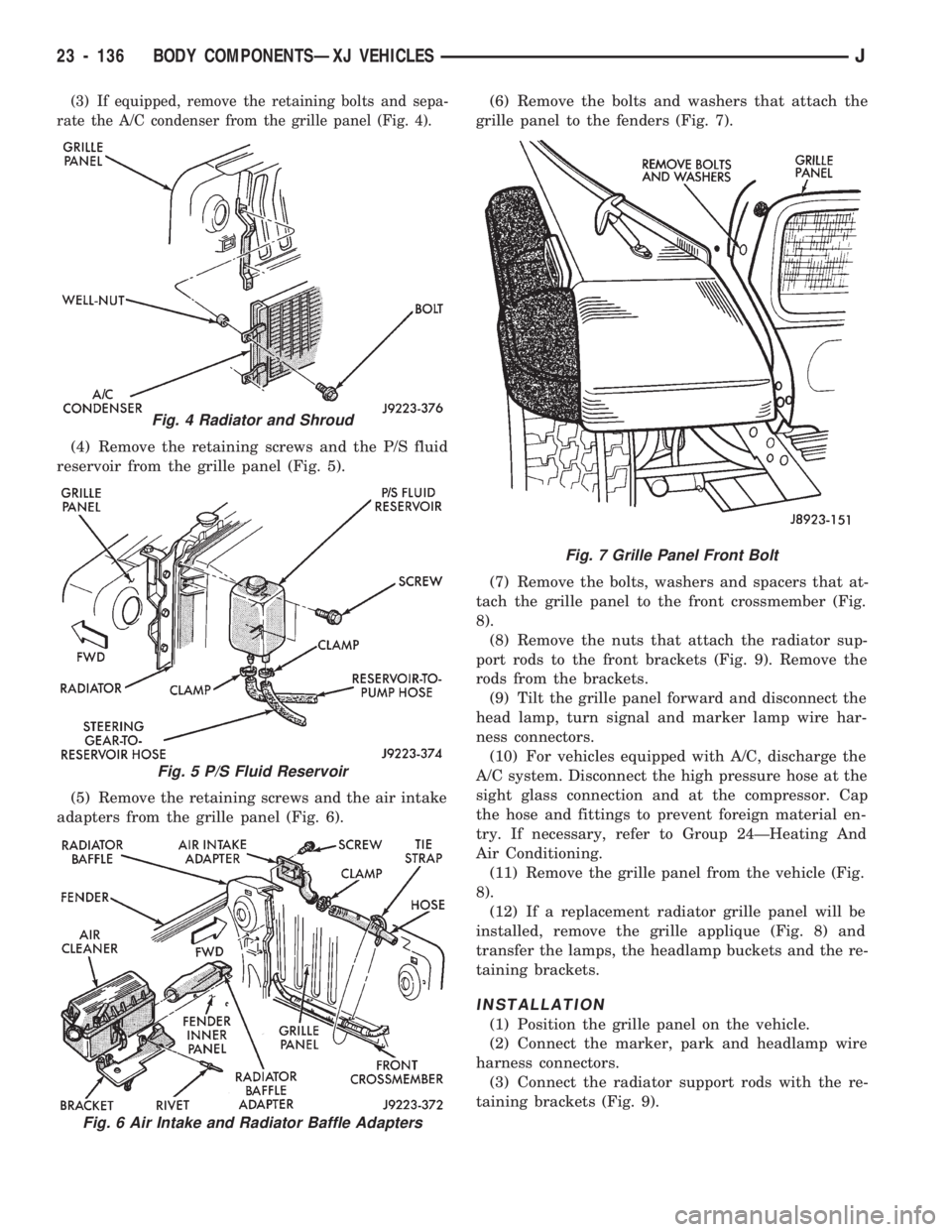
(3) If equipped, remove the retaining bolts and sepa-
rate the A/C condenser from the grille panel (Fig. 4).
(4) Remove the retaining screws and the P/S fluid
reservoir from the grille panel (Fig. 5).
(5) Remove the retaining screws and the air intake
adapters from the grille panel (Fig. 6).(6) Remove the bolts and washers that attach the
grille panel to the fenders (Fig. 7).
(7) Remove the bolts, washers and spacers that at-
tach the grille panel to the front crossmember (Fig.
8).
(8) Remove the nuts that attach the radiator sup-
port rods to the front brackets (Fig. 9). Remove the
rods from the brackets.
(9) Tilt the grille panel forward and disconnect the
head lamp, turn signal and marker lamp wire har-
ness connectors.
(10) For vehicles equipped with A/C, discharge the
A/C system. Disconnect the high pressure hose at the
sight glass connection and at the compressor. Cap
the hose and fittings to prevent foreign material en-
try. If necessary, refer to Group 24ÐHeating And
Air Conditioning.
(11) Remove the grille panel from the vehicle (Fig.
8).
(12) If a replacement radiator grille panel will be
installed, remove the grille applique (Fig. 8) and
transfer the lamps, the headlamp buckets and the re-
taining brackets.
INSTALLATION
(1) Position the grille panel on the vehicle.
(2) Connect the marker, park and headlamp wire
harness connectors.
(3) Connect the radiator support rods with the re-
taining brackets (Fig. 9).
Fig. 4 Radiator and Shroud
Fig. 5 P/S Fluid Reservoir
Fig. 6 Air Intake and Radiator Baffle Adapters
Fig. 7 Grille Panel Front Bolt
23 - 136 BODY COMPONENTSÐXJ VEHICLESJ
Page 1704 of 1784
(12) Fill and bleed the cooling system.
FRESH AIR DOOR VACUUM MOTOR
REMOVAL
(1) Remove the glove box and assist handle.
(2) Disconnect the vacuum hose from the motor.
(3) Remove the motor lever retaining clip.
(4) Remove the motor attaching nuts and remove
the motor from the fresh air duct.
INSTALLATION
(1) Position the motor on the fresh air duct and in-
stall the motor attaching nuts.
(2) Align the motor lever with the air door lever
and install the lever retaining clip.
(3) Connect the vacuum hose to the motor.
(4) Install the glove box and assist handle.
FRESH AIR INTAKE DUCT
REMOVAL
WARNING: HOT ENGINE COOLANT CAN CAUSE
SEVERE BURNS. DO NOT OPEN THE RADIATOR
DRAIN COCK WHEN THE COOLING SYSTEM IS
HOT AND PRESSURIZED. ALLOW THE COOLANT
TO DECREASE TO ROOM TEMPERATURE BEFORE
STARTING REPAIR OPERATIONS.
(1) Drain approximately 1.9 liters (2 qts) of coolant
from the radiator. Drain the coolant into a clean con-
tainer.
(2) Disconnect the heater hoses.
(3) Remove the nuts attaching the heater housing
studs to the dash panel from inside the engine com-
partment.
(4) Disconnect the speedometer cable.
(5) Remove the glove box and assist handle.
(6) Tilt the heater housing back and pull it rear-
ward and out from under the instrument panel.
(7) Disconnect the vent cables.
(8) Remove the fresh air intake grille from the
cowl.
(9) Remove the fresh air intake duct.
INSTALLATION
(1) Install the fresh air intake duct.
(2) Install the defroster nozzle and duct.
(3) Raise and secure the windshield.
(4) Install the fresh air grille on the cowl.
(5) Install the vent cables.
(6) Position the heater housing on the dash panel.
Be sure all the housing studs extend through the
dash panel.
(7) Install the seals on the blower motor and
heater core inlet and outlet tubes.
(8) Install the attaching nuts on the heater hous-
ing studs.CAUTION: DO NOT over tighten the attaching nuts.
The housing could become distorted causing air
leaks and improper heater door operation. Tighten
the nuts alternately and evenly until 2 stud threads
are visible beyond each nut.
(9) Install the glove box and assist handle.
(10) Connect the speedometer cable.
(11) Connect the heater hoses.
(12) Fill and bleed the cooling system.
DESCRIPTION (AIR CONDITIONING)
The evaporator, blower fan and motor, thermostat,
expansion valve, capillary tube, air outlets and sys-
tem controls are located in the evaporator housing.
The evaporator housing is mounted under the instru-
ment panel. The compressor, condenser, receiver-
dryer and refrigerant lines are located in the engine
compartment.
A rotary-type compressor with magnetic clutch op-
erated drive pulley is used for all vehicles equipped
with air conditioning.
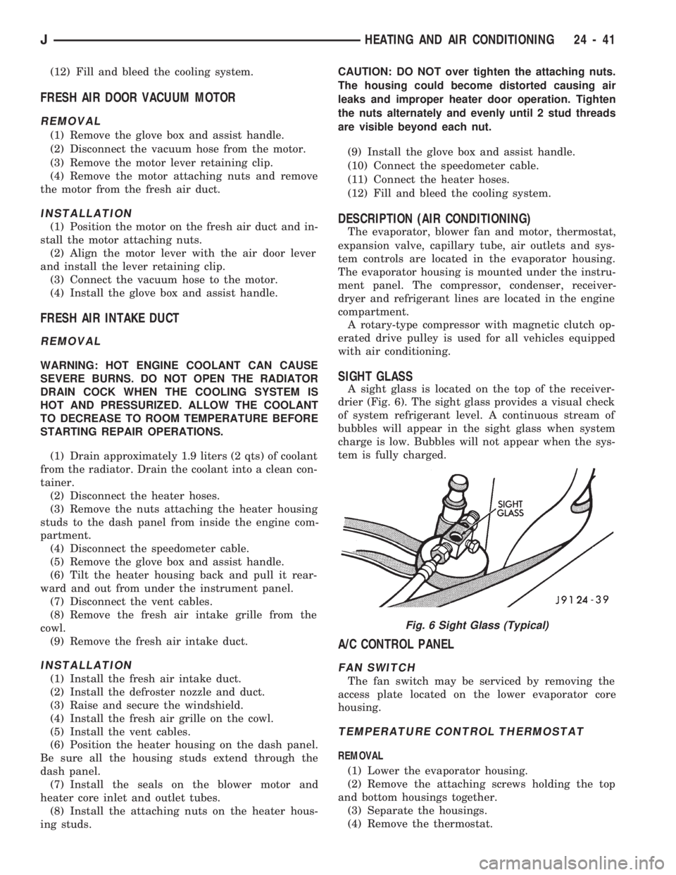
SIGHT GLASS
A sight glass is located on the top of the receiver-
drier (Fig. 6). The sight glass provides a visual check
of system refrigerant level. A continuous stream of
bubbles will appear in the sight glass when system
charge is low. Bubbles will not appear when the sys-
tem is fully charged.
A/C CONTROL PANEL
FAN SWITCH
The fan switch may be serviced by removing the
access plate located on the lower evaporator core
housing.
TEMPERATURE CONTROL THERMOSTAT
REMOVAL
(1) Lower the evaporator housing.
(2) Remove the attaching screws holding the top
and bottom housings together.
(3) Separate the housings.
(4) Remove the thermostat.
Fig. 6 Sight Glass (Typical)
JHEATING AND AIR CONDITIONING 24 - 41
Page 1705 of 1784
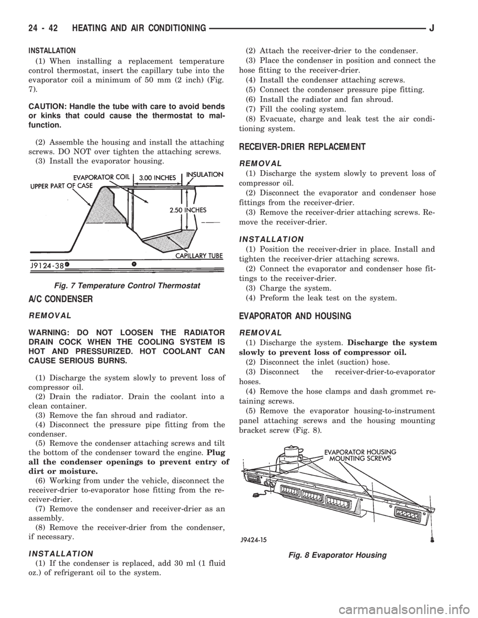
INSTALLATION
(1) When installing a replacement temperature
control thermostat, insert the capillary tube into the
evaporator coil a minimum of 50 mm (2 inch) (Fig.
7).
CAUTION: Handle the tube with care to avoid bends
or kinks that could cause the thermostat to mal-
function.
(2) Assemble the housing and install the attaching
screws. DO NOT over tighten the attaching screws.
(3) Install the evaporator housing.
A/C CONDENSER
REMOVAL
WARNING: DO NOT LOOSEN THE RADIATOR
DRAIN COCK WHEN THE COOLING SYSTEM IS
HOT AND PRESSURIZED. HOT COOLANT CAN
CAUSE SERIOUS BURNS.
(1) Discharge the system slowly to prevent loss of
compressor oil.
(2) Drain the radiator. Drain the coolant into a
clean container.
(3) Remove the fan shroud and radiator.
(4) Disconnect the pressure pipe fitting from the
condenser.
(5) Remove the condenser attaching screws and tilt
the bottom of the condenser toward the engine.Plug
all the condenser openings to prevent entry of
dirt or moisture.
(6) Working from under the vehicle, disconnect the
receiver-drier to-evaporator hose fitting from the re-
ceiver-drier.
(7) Remove the condenser and receiver-drier as an
assembly.
(8) Remove the receiver-drier from the condenser,
if necessary.
INSTALLATION
(1) If the condenser is replaced, add 30 ml (1 fluid
oz.) of refrigerant oil to the system.(2) Attach the receiver-drier to the condenser.
(3) Place the condenser in position and connect the
hose fitting to the receiver-drier.
(4) Install the condenser attaching screws.
(5) Connect the condenser pressure pipe fitting.
(6) Install the radiator and fan shroud.
(7) Fill the cooling system.
(8) Evacuate, charge and leak test the air condi-
tioning system.
RECEIVER-DRIER REPLACEMENT
REMOVAL
(1) Discharge the system slowly to prevent loss of
compressor oil.
(2) Disconnect the evaporator and condenser hose
fittings from the receiver-drier.
(3) Remove the receiver-drier attaching screws. Re-
move the receiver-drier.
INSTALLATION
(1) Position the receiver-drier in place. Install and
tighten the receiver-drier attaching screws.
(2) Connect the evaporator and condenser hose fit-
tings to the receiver-drier.
(3) Charge the system.
(4) Preform the leak test on the system.
EVAPORATOR AND HOUSING
REMOVAL
(1) Discharge the system.Discharge the system
slowly to prevent loss of compressor oil.
(2) Disconnect the inlet (suction) hose.
(3) Disconnect the receiver-drier-to-evaporator
hoses.
(4) Remove the hose clamps and dash grommet re-
taining screws.
(5) Remove the evaporator housing-to-instrument
panel attaching screws and the housing mounting
bracket screw (Fig. 8).
Fig. 7 Temperature Control Thermostat
Fig. 8 Evaporator Housing
24 - 42 HEATING AND AIR CONDITIONINGJ