1994 JEEP CHEROKEE wheel bolts
[x] Cancel search: wheel boltsPage 1176 of 1784
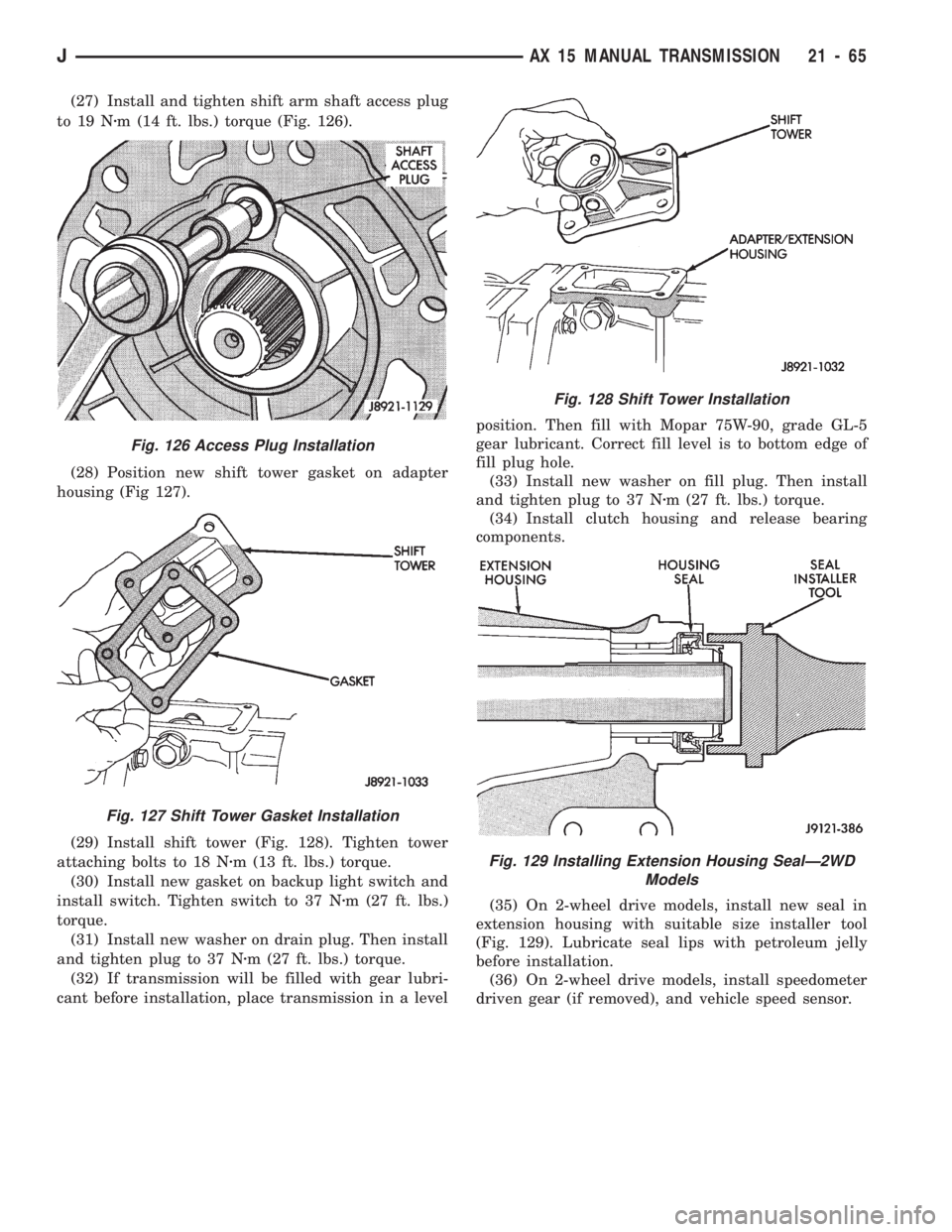
(27) Install and tighten shift arm shaft access plug
to 19 Nzm (14 ft. lbs.) torque (Fig. 126).
(28) Position new shift tower gasket on adapter
housing (Fig 127).
(29) Install shift tower (Fig. 128). Tighten tower
attaching bolts to 18 Nzm (13 ft. lbs.) torque.
(30) Install new gasket on backup light switch and
install switch. Tighten switch to 37 Nzm (27 ft. lbs.)
torque.
(31) Install new washer on drain plug. Then install
and tighten plug to 37 Nzm (27 ft. lbs.) torque.
(32) If transmission will be filled with gear lubri-
cant before installation, place transmission in a levelposition. Then fill with Mopar 75W-90, grade GL-5
gear lubricant. Correct fill level is to bottom edge of
fill plug hole.
(33) Install new washer on fill plug. Then install
and tighten plug to 37 Nzm (27 ft. lbs.) torque.
(34) Install clutch housing and release bearing
components.
(35) On 2-wheel drive models, install new seal in
extension housing with suitable size installer tool
(Fig. 129). Lubricate seal lips with petroleum jelly
before installation.
(36) On 2-wheel drive models, install speedometer
driven gear (if removed), and vehicle speed sensor.
Fig. 126 Access Plug Installation
Fig. 127 Shift Tower Gasket Installation
Fig. 128 Shift Tower Installation
Fig. 129 Installing Extension Housing SealÐ2WD
Models
JAX 15 MANUAL TRANSMISSION 21 - 65
Page 1565 of 1784
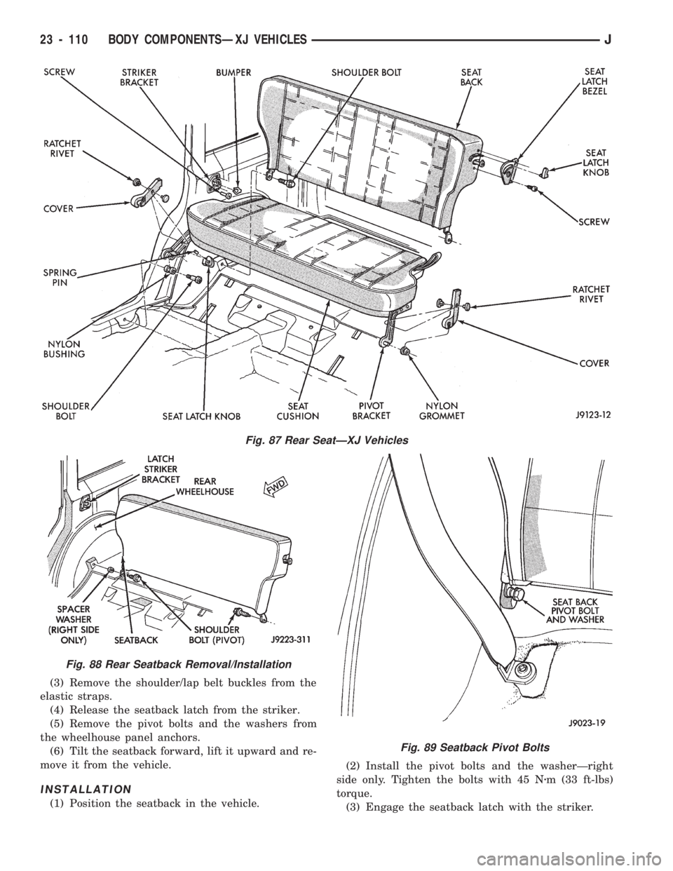
(3) Remove the shoulder/lap belt buckles from the
elastic straps.
(4) Release the seatback latch from the striker.
(5) Remove the pivot bolts and the washers from
the wheelhouse panel anchors.
(6) Tilt the seatback forward, lift it upward and re-
move it from the vehicle.
INSTALLATION
(1) Position the seatback in the vehicle.(2) Install the pivot bolts and the washerÐright
side only. Tighten the bolts with 45 Nzm (33 ft-lbs)
torque.
(3) Engage the seatback latch with the striker.
Fig. 87 Rear SeatÐXJ Vehicles
Fig. 88 Rear Seatback Removal/Installation
Fig. 89 Seatback Pivot Bolts
23 - 110 BODY COMPONENTSÐXJ VEHICLESJ
Page 1599 of 1784
INSTALLATION
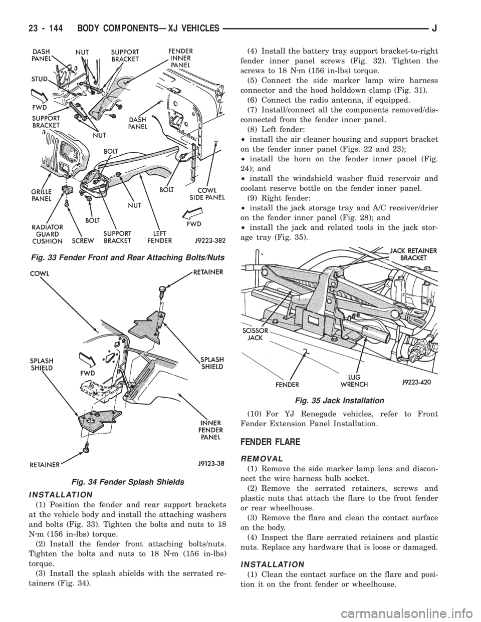
(1) Position the fender and rear support brackets
at the vehicle body and install the attaching washers
and bolts (Fig. 33). Tighten the bolts and nuts to 18
Nzm (156 in-lbs) torque.
(2) Install the fender front attaching bolts/nuts.
Tighten the bolts and nuts to 18 Nzm (156 in-lbs)
torque.
(3) Install the splash shields with the serrated re-
tainers (Fig. 34).(4) Install the battery tray support bracket-to-right
fender inner panel screws (Fig. 32). Tighten the
screws to 18 Nzm (156 in-lbs) torque.
(5) Connect the side marker lamp wire harness
connector and the hood holddown clamp (Fig. 31).
(6) Connect the radio antenna, if equipped.
(7) Install/connect all the components removed/dis-
connected from the fender inner panel.
(8) Left fender:
²install the air cleaner housing and support bracket
on the fender inner panel (Figs. 22 and 23);
²install the horn on the fender inner panel (Fig.
24); and
²install the windshield washer fluid reservoir and
coolant reserve bottle on the fender inner panel.
(9) Right fender:
²install the jack storage tray and A/C receiver/drier
on the fender inner panel (Fig. 28); and
²install the jack and related tools in the jack stor-
age tray (Fig. 35).
(10) For YJ Renegade vehicles, refer to Front
Fender Extension Panel Installation.
FENDER FLARE
REMOVAL
(1) Remove the side marker lamp lens and discon-
nect the wire harness bulb socket.
(2) Remove the serrated retainers, screws and
plastic nuts that attach the flare to the front fender
or rear wheelhouse.
(3) Remove the flare and clean the contact surface
on the body.
(4) Inspect the flare serrated retainers and plastic
nuts. Replace any hardware that is loose or damaged.
INSTALLATION
(1) Clean the contact surface on the flare and posi-
tion it on the front fender or wheelhouse.
Fig. 33 Fender Front and Rear Attaching Bolts/Nuts
Fig. 34 Fender Splash Shields
Fig. 35 Jack Installation
23 - 144 BODY COMPONENTSÐXJ VEHICLESJ
Page 1601 of 1784
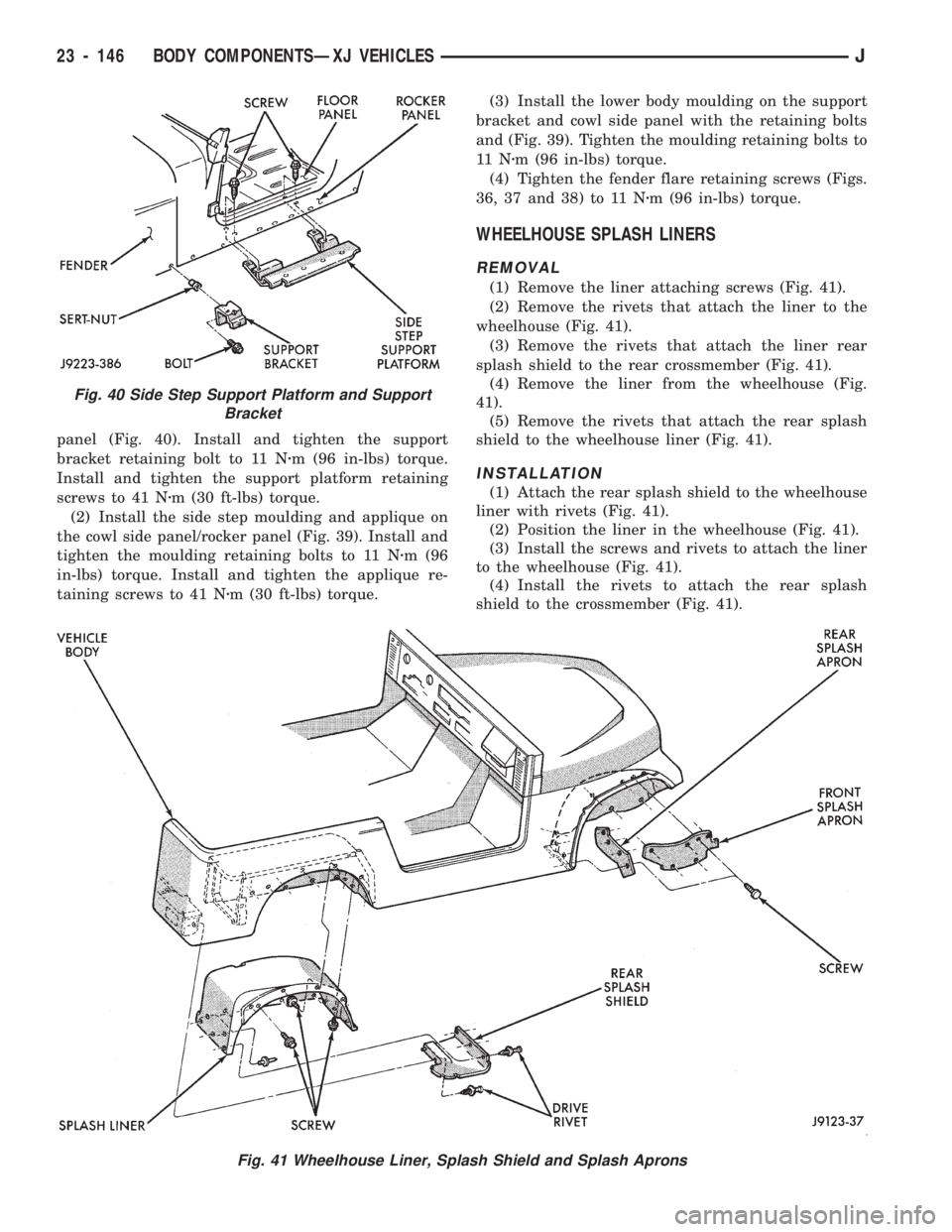
panel (Fig. 40). Install and tighten the support
bracket retaining bolt to 11 Nzm (96 in-lbs) torque.
Install and tighten the support platform retaining
screws to 41 Nzm (30 ft-lbs) torque.
(2) Install the side step moulding and applique on
the cowl side panel/rocker panel (Fig. 39). Install and
tighten the moulding retaining bolts to 11 Nzm (96
in-lbs) torque. Install and tighten the applique re-
taining screws to 41 Nzm (30 ft-lbs) torque.(3) Install the lower body moulding on the support
bracket and cowl side panel with the retaining bolts
and (Fig. 39). Tighten the moulding retaining bolts to
11 Nzm (96 in-lbs) torque.
(4) Tighten the fender flare retaining screws (Figs.
36, 37 and 38) to 11 Nzm (96 in-lbs) torque.
WHEELHOUSE SPLASH LINERS
REMOVAL
(1) Remove the liner attaching screws (Fig. 41).
(2) Remove the rivets that attach the liner to the
wheelhouse (Fig. 41).
(3) Remove the rivets that attach the liner rear
splash shield to the rear crossmember (Fig. 41).
(4) Remove the liner from the wheelhouse (Fig.
41).
(5) Remove the rivets that attach the rear splash
shield to the wheelhouse liner (Fig. 41).
INSTALLATION
(1) Attach the rear splash shield to the wheelhouse
liner with rivets (Fig. 41).
(2) Position the liner in the wheelhouse (Fig. 41).
(3) Install the screws and rivets to attach the liner
to the wheelhouse (Fig. 41).
(4) Install the rivets to attach the rear splash
shield to the crossmember (Fig. 41).
Fig. 41 Wheelhouse Liner, Splash Shield and Splash Aprons
Fig. 40 Side Step Support Platform and Support
Bracket
23 - 146 BODY COMPONENTSÐXJ VEHICLESJ
Page 1606 of 1784
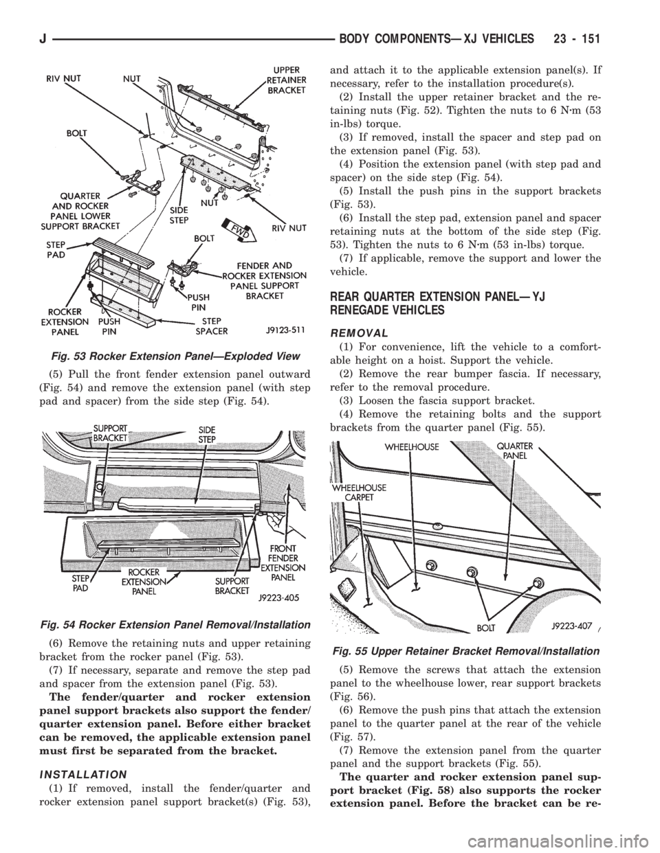
(5) Pull the front fender extension panel outward
(Fig. 54) and remove the extension panel (with step
pad and spacer) from the side step (Fig. 54).
(6) Remove the retaining nuts and upper retaining
bracket from the rocker panel (Fig. 53).
(7) If necessary, separate and remove the step pad
and spacer from the extension panel (Fig. 53).
The fender/quarter and rocker extension
panel support brackets also support the fender/
quarter extension panel. Before either bracket
can be removed, the applicable extension panel
must first be separated from the bracket.
INSTALLATION
(1) If removed, install the fender/quarter and
rocker extension panel support bracket(s) (Fig. 53),and attach it to the applicable extension panel(s). If
necessary, refer to the installation procedure(s).
(2) Install the upper retainer bracket and the re-
taining nuts (Fig. 52). Tighten the nuts to 6 Nzm (53
in-lbs) torque.
(3) If removed, install the spacer and step pad on
the extension panel (Fig. 53).
(4) Position the extension panel (with step pad and
spacer) on the side step (Fig. 54).
(5) Install the push pins in the support brackets
(Fig. 53).
(6) Install the step pad, extension panel and spacer
retaining nuts at the bottom of the side step (Fig.
53). Tighten the nuts to 6 Nzm (53 in-lbs) torque.
(7) If applicable, remove the support and lower the
vehicle.
REAR QUARTER EXTENSION PANELÐYJ
RENEGADE VEHICLES
REMOVAL
(1) For convenience, lift the vehicle to a comfort-
able height on a hoist. Support the vehicle.
(2) Remove the rear bumper fascia. If necessary,
refer to the removal procedure.
(3) Loosen the fascia support bracket.
(4) Remove the retaining bolts and the support
brackets from the quarter panel (Fig. 55).
(5) Remove the screws that attach the extension
panel to the wheelhouse lower, rear support brackets
(Fig. 56).
(6) Remove the push pins that attach the extension
panel to the quarter panel at the rear of the vehicle
(Fig. 57).
(7) Remove the extension panel from the quarter
panel and the support brackets (Fig. 55).
The quarter and rocker extension panel sup-
port bracket (Fig. 58) also supports the rocker
extension panel. Before the bracket can be re-
Fig. 55 Upper Retainer Bracket Removal/Installation
Fig. 53 Rocker Extension PanelÐExploded View
Fig. 54 Rocker Extension Panel Removal/Installation
JBODY COMPONENTSÐXJ VEHICLES 23 - 151
Page 1627 of 1784
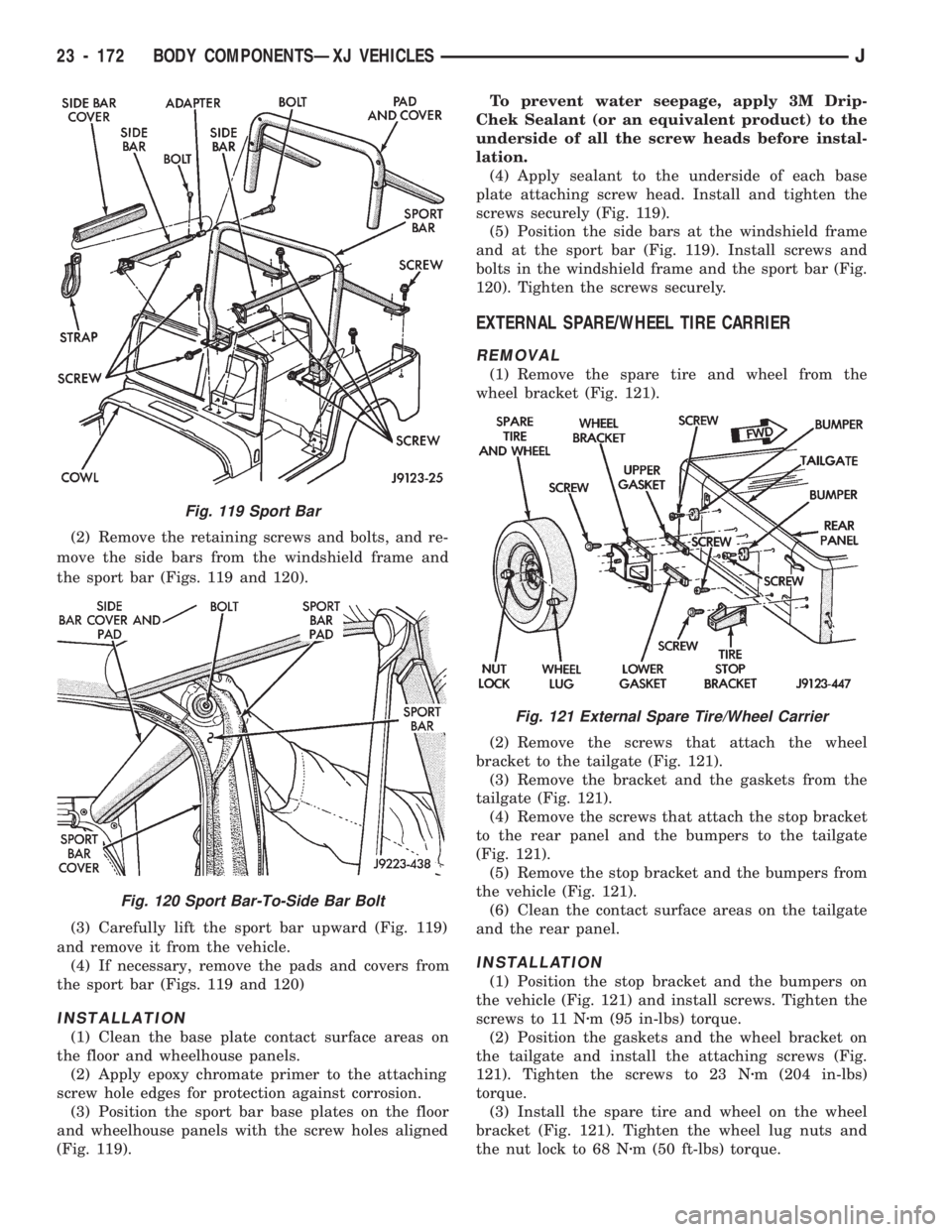
(2) Remove the retaining screws and bolts, and re-
move the side bars from the windshield frame and
the sport bar (Figs. 119 and 120).
(3) Carefully lift the sport bar upward (Fig. 119)
and remove it from the vehicle.
(4) If necessary, remove the pads and covers from
the sport bar (Figs. 119 and 120)
INSTALLATION
(1) Clean the base plate contact surface areas on
the floor and wheelhouse panels.
(2) Apply epoxy chromate primer to the attaching
screw hole edges for protection against corrosion.
(3) Position the sport bar base plates on the floor
and wheelhouse panels with the screw holes aligned
(Fig. 119).To prevent water seepage, apply 3M Drip-
Chek Sealant (or an equivalent product) to the
underside of all the screw heads before instal-
lation.
(4) Apply sealant to the underside of each base
plate attaching screw head. Install and tighten the
screws securely (Fig. 119).
(5) Position the side bars at the windshield frame
and at the sport bar (Fig. 119). Install screws and
bolts in the windshield frame and the sport bar (Fig.
120). Tighten the screws securely.
EXTERNAL SPARE/WHEEL TIRE CARRIER
REMOVAL
(1) Remove the spare tire and wheel from the
wheel bracket (Fig. 121).
(2) Remove the screws that attach the wheel
bracket to the tailgate (Fig. 121).
(3) Remove the bracket and the gaskets from the
tailgate (Fig. 121).
(4) Remove the screws that attach the stop bracket
to the rear panel and the bumpers to the tailgate
(Fig. 121).
(5) Remove the stop bracket and the bumpers from
the vehicle (Fig. 121).
(6) Clean the contact surface areas on the tailgate
and the rear panel.
INSTALLATION
(1) Position the stop bracket and the bumpers on
the vehicle (Fig. 121) and install screws. Tighten the
screws to 11 Nzm (95 in-lbs) torque.
(2) Position the gaskets and the wheel bracket on
the tailgate and install the attaching screws (Fig.
121). Tighten the screws to 23 Nzm (204 in-lbs)
torque.
(3) Install the spare tire and wheel on the wheel
bracket (Fig. 121). Tighten the wheel lug nuts and
the nut lock to 68 Nzm (50 ft-lbs) torque.
Fig. 119 Sport Bar
Fig. 120 Sport Bar-To-Side Bar Bolt
Fig. 121 External Spare Tire/Wheel Carrier
23 - 172 BODY COMPONENTSÐXJ VEHICLESJ
Page 1681 of 1784
²Used belt tensionÐ623-712 N (140-160 lb-f).
(5) Remove the tape or plastic plugs from all the
suction and discharge openings and install the ser-
vice valves on the compressor.
(6) Connect the clutch lead wire.
(7) Connect negative cable to battery.
(8) Evacuate, charge and test the system for leaks.
MAGNETIC CLUTCH
The magnetic clutch consists of a stationary elec-
tro-magnetic coil and a rotating pulley and plate as-
sembly.
The electromagnetic coil is retained on the com-
pressor with a snap ring and is dimpled to maintain
its position.The pulley and plate assembly are mounted on the
compressor shaft.
When the compressor is not in operation, the pul-
ley free wheels on the clutch hub bearing. When the
coil is energized the plate is magnetically engaged
with the pulley and turns the compressor shaft.
REMOVAL
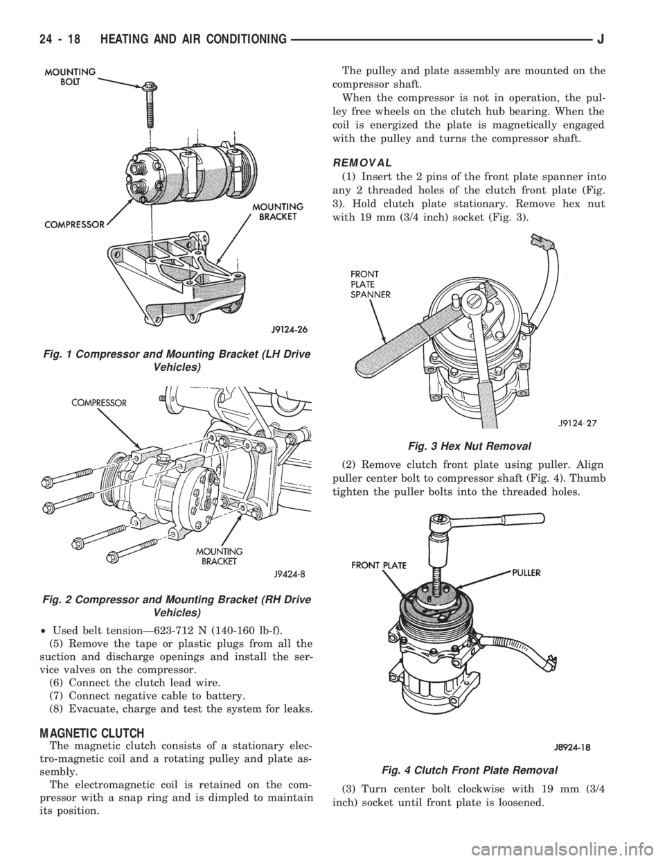
(1) Insert the 2 pins of the front plate spanner into
any 2 threaded holes of the clutch front plate (Fig.
3). Hold clutch plate stationary. Remove hex nut
with 19 mm (3/4 inch) socket (Fig. 3).
(2) Remove clutch front plate using puller. Align
puller center bolt to compressor shaft (Fig. 4). Thumb
tighten the puller bolts into the threaded holes.
(3) Turn center bolt clockwise with 19 mm (3/4
inch) socket until front plate is loosened.
Fig. 1 Compressor and Mounting Bracket (LH Drive
Vehicles)
Fig. 2 Compressor and Mounting Bracket (RH Drive
Vehicles)
Fig. 3 Hex Nut Removal
Fig. 4 Clutch Front Plate Removal
24 - 18 HEATING AND AIR CONDITIONINGJ