1994 JEEP CHEROKEE wheel bolts
[x] Cancel search: wheel boltsPage 913 of 1784
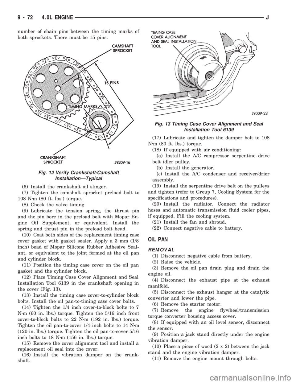
number of chain pins between the timing marks of
both sprockets. There must be 15 pins.
(6) Install the crankshaft oil slinger.
(7) Tighten the camshaft sprocket preload bolt to
108 Nzm (80 ft. lbs.) torque.
(8) Check the valve timing.
(9) Lubricate the tension spring, the thrust pin
and the pin bore in the preload bolt with Mopar En-
gine Oil Supplement, or equivalent. Install the
spring and thrust pin in the preload bolt head.
(10) Coat both sides of the replacement timing case
cover gasket with gasket sealer. Applya3mm(1/8
inch) bead of Mopar Silicone Rubber Adhesive Seal-
ant, or equivalent to the joint formed at the oil pan
and cylinder block.
(11) Position the timing case cover on the oil pan
gasket and the cylinder block.
(12) Place Timing Case Cover Alignment and Seal
Installation Tool 6139 in the crankshaft opening in
the cover (Fig. 13).
(13) Install the timing case cover-to-cylinder block
bolts. Install the oil pan-to-timing case cover bolts.
(14) Tighten the 1/4 inch cover-to-block bolts to 7
Nzm (60 in. lbs.) torque. Tighten the 5/16 inch front
cover-to-block bolts to 22 Nzm (192 in. lbs.) torque.
Tighten the oil pan-to-cover 1/4 inch bolts to 14 Nzm
(120 in. lbs.) torque. Tighten the oil pan-to-cover 5/16
inch bolts to 18 Nzm (156 in. lbs.) torque.
(15) Remove the cover alignment tool and install a
replacement oil seal into the cover.
(16) Install the vibration damper on the crank-
shaft.(17) Lubricate and tighten the damper bolt to 108
Nzm (80 ft. lbs.) torque.
(18) If equipped with air conditioning:
(a) Install the A/C compressor serpentine drive
belt idler pulley.
(b) Install the generator.
(c) Install the A/C condenser and receiver/drier
assembly.
(19) Install the serpentine drive belt on the pulleys
and tighten (refer to Group 7, Cooling System for the
specifications and procedures).
(20) Install the radiator. Connect the radiator
hoses and automatic transmission fluid cooler pipes,
if equipped. Fill the cooling system.
(21) Install the fan and shroud.
(22) Connect negative cable to battery.
OIL PAN
REMOVAL
(1) Disconnect negative cable from battery.
(2) Raise the vehicle.
(3) Remove the oil pan drain plug and drain the
engine oil.
(4) Disconnect the exhaust pipe at the exhaust
manifold.
(5) Disconnect the exhaust hanger at the catalytic
converter and lower the pipe.
(6) Remove the starter motor.
(7) Remove the engine flywheel/transmission
torque converter housing access cover.
(8) If equipped with an oil level sensor, disconnect
the sensor.
(9) Position a jack stand directly under the engine
vibration damper.
(10) Place a piece of wood (2 x 2) between the jack
stand and the engine vibration damper.
(11) Remove the engine mount through bolts.
Fig. 12 Verify Crankshaft/Camshaft
InstallationÐTypical
Fig. 13 Timing Case Cover Alignment and Seal
Installation Tool 6139
9 - 72 4.0L ENGINEJ
Page 914 of 1784
(12) Using the jack stand, raise the engine until
adequate clearance is obtained to remove the oil pan.
(13) Remove the oil pan bolts. Carefully slide the
oil pan and gasket to the rear. If equipped with an
oil level sensor, take care not to damage the sensor.
CLEANING
Clean the block and pan gasket surfaces.
INSTALLATION
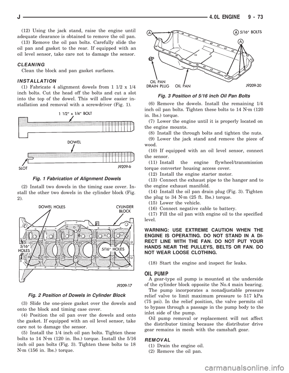
(1) Fabricate 4 alignment dowels from 1 1/2 x 1/4
inch bolts. Cut the head off the bolts and cut a slot
into the top of the dowel. This will allow easier in-
stallation and removal with a screwdriver (Fig. 1).
(2) Install two dowels in the timing case cover. In-
stall the other two dowels in the cylinder block (Fig.
2).
(3) Slide the one-piece gasket over the dowels and
onto the block and timing case cover.
(4) Position the oil pan over the dowels and onto
the gasket. If equipped with an oil level sensor, take
care not to damage the sensor.
(5) Install the 1/4 inch oil pan bolts. Tighten these
bolts to 14 Nzm (120 in. lbs.) torque. Install the 5/16
inch oil pan bolts (Fig. 3). Tighten these bolts to 18
Nzm (156 in. lbs.) torque.(6) Remove the dowels. Install the remaining 1/4
inch oil pan bolts. Tighten these bolts to 14 Nzm (120
in. lbs.) torque.
(7) Lower the engine until it is properly located on
the engine mounts.
(8) Install the through bolts and tighten the nuts.
(9) Lower the jack stand and remove the piece of
wood.
(10) If equipped with an oil level sensor, connect
the sensor.
(11) Install the engine flywheel/transmission
torque converter housing access cover.
(12) Install the engine starter motor.
(13) Connect the exhaust pipe to the hanger and to
the engine exhaust manifold.
(14) Install the oil pan drain plug (Fig. 3). Tighten
the plug to 34 Nzm (25 ft. lbs.) torque.
(15) Lower the vehicle.
(16) Connect negative cable to battery.
(17) Fill the oil pan with engine oil to the specified
level.
WARNING: USE EXTREME CAUTION WHEN THE
ENGINE IS OPERATING. DO NOT STAND IN A DI-
RECT LINE WITH THE FAN. DO NOT PUT YOUR
HANDS NEAR THE PULLEYS, BELTS OR FAN. DO
NOT WEAR LOOSE CLOTHING.
(18) Start the engine and inspect for leaks.
OIL PUMP
A gear-type oil pump is mounted at the underside
of the cylinder block opposite the No.4 main bearing.
The pump incorporates a nonadjustable pressure
relief valve to limit maximum pressure to 517 kPa
(75 psi). In the relief position, the valve permits oil
to bypass through a passage in the pump body to the
inlet side of the pump.
Oil pump removal or replacement will not affect
the distributor timing because the distributor drive
gear remains in mesh with the camshaft gear.
REMOVAL
(1) Drain the engine oil.
(2) Remove the oil pan.
Fig. 1 Fabrication of Alignment Dowels
Fig. 2 Position of Dowels in Cylinder Block
Fig. 3 Position of 5/16 inch Oil Pan Bolts
J4.0L ENGINE 9 - 73
Page 926 of 1784
(9) Install the rear main bearing cap. DO NOT
strike the cap more than twice for proper engage-
ment.
(10) Tighten all main bearing bolts to 108 Nzm (80
ft. lbs.) torque.
(11) Install the oil pan gasket and oil pan.
(12) Install the engine flywheel or converter drive
plate.
CYLINDER BLOCK
Remove the Engine Assembly from the vehicle.
DISASSEMBLY
Refer to the applicable sections for detailed instruc-
tions.
(1) Drain the engine oil. Remove and discard the
oil filter.
(2) Remove the water pump from the cylinder
block.
(3) Remove the vibration damper.
(4) Remove the timing case cover and lay the cover
upside down.
(5) Position a drift punch into the slot in the back
of the cover and tap the old seal out.
(6) Remove the oil slinger from crankshaft.
(7) Remove the camshaft retaining bolt and re-
move the sprockets and chain as an assembly.
(8) Remove the camshaft.
(9) Remove the oil pan and gasket.
(10) Remove the front and rear oil galley plugs.
(11) Remove the oil pump.
(12) Remove the connecting rods and the pistons.
Remove the connecting rod and piston assemblies
through the top of the cylinder bores.
(13) Remove the crankshaft.
CLEANING
Thoroughly clean the oil pan and engine block gas-
ket surfaces.
Use compressed air to clean out:
²The galley at the oil filter adaptor hole, the filter
bypass hole.
²The front and rear oil galley holes.
²The feed holes for the crankshaft main bearings.
Once the block has been completely cleaned, apply
Loctite PST pipe sealant with Teflon 592 to the
threads of the front and rear oil galley plugs.
Tighten the plugs to 41 Nzm (30 ft. lbs.) torque.
INSPECTIONÐCYLINDER BORE
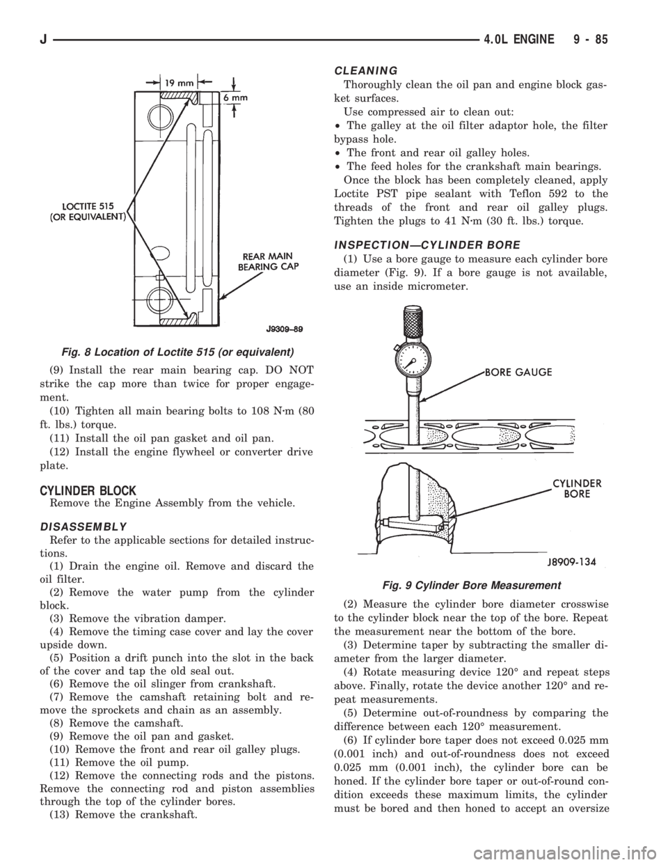
(1) Use a bore gauge to measure each cylinder bore
diameter (Fig. 9). If a bore gauge is not available,
use an inside micrometer.
(2) Measure the cylinder bore diameter crosswise
to the cylinder block near the top of the bore. Repeat
the measurement near the bottom of the bore.
(3) Determine taper by subtracting the smaller di-
ameter from the larger diameter.
(4) Rotate measuring device 120É and repeat steps
above. Finally, rotate the device another 120É and re-
peat measurements.
(5) Determine out-of-roundness by comparing the
difference between each 120É measurement.
(6) If cylinder bore taper does not exceed 0.025 mm
(0.001 inch) and out-of-roundness does not exceed
0.025 mm (0.001 inch), the cylinder bore can be
honed. If the cylinder bore taper or out-of-round con-
dition exceeds these maximum limits, the cylinder
must be bored and then honed to accept an oversize
Fig. 8 Location of Loctite 515 (or equivalent)
Fig. 9 Cylinder Bore Measurement
J4.0L ENGINE 9 - 85
Page 1051 of 1784
STEERING LINKAGEÐXJ
INDEX
page page
Drag Link.............................. 14
Pitman Arm............................. 15
Service Information....................... 14Steering Dampener....................... 15
Tie Rod ................................ 14
SERVICE INFORMATION
The steering linkage consists of a pitman arm, drag
link, tie rod, and steering dampener. Adjustment
sleeves are used on the tie rod and drag link for toe
and steering wheel alignment.
Refer to Group 2, Front Suspension and Axle for
additional information.
The tie-rod end ball stud seals should be inspected
during all oil changes.
A damaged ball stud seal requires removal of the
seal. Inspect the tie-rod end ball stud at the throat
opening. Check for lubricant loss, contamination, ball
stud wear or corrosion. If these conditions exist, re-
place the tie-rod. A replacement seal can be installed
if lubricant is in good condition. Otherwise, a com-
plete replacement ball stud end should be installed.
Lubricate the tie-rod end with MOPARtMulti-Mile-
age Lubricant, or equivalent product.
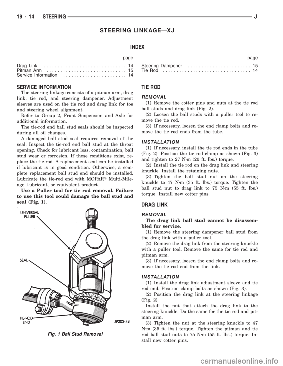
Use a Puller tool for tie rod removal. Failure
to use this tool could damage the ball stud and
seal (Fig. 1).
TIE ROD
REMOVAL
(1) Remove the cotter pins and nuts at the tie rod
ball studs and drag link (Fig. 2).
(2) Loosen the ball studs with a puller tool to re-
move the tie rod.
(3) If necessary, loosen the end clamp bolts and re-
move the tie rod ends from the tube.
INSTALLATION
(1) If necessary, install the tie rod ends in the tube
(Fig. 2). Position the tie rod clamp as shown (Fig. 3)
and tighten to 27 Nzm (20 ft. lbs.) torque.
(2) Install the tie rod on the drag link and steering
knuckle. Install the retaining nuts.
(3) Tighten the ball stud nut on the steering
knuckle to 47 Nzm (35 ft. lbs.) torque. Tighten the
ball stud nut to drag link to 75 Nzm (55 ft. lbs.)
torque. Install new cotter pins.
DRAG LINK
REMOVAL
The drag link ball stud cannot be disassem-
bled for service.
(1) Remove the steering dampener ball stud from
the drag link with a puller tool.
(2) Remove the drag link from the steering knuckle
with a puller tool. Remove the same for tie rod and
pitman arm.
(3) If necessary, loosen the end clamp bolts and re-
move the tie rod end from the link.
INSTALLATION
(1) Install the drag link adjustment sleeve and tie
rod end. Position clamp bolts as shown (Fig. 3).
(2) Position the drag link at the steering linkage
(Fig. 2).
Install the nut that attach the drag link to the
steering knuckle. Do the same for the tie rod and pit-
man arm.
(3) Tighten the nut at the steering knuckle to 47
Nzm (35 ft. lbs.) torque. Tighten the pitman and tie
rod ball stud nuts to 75 Nzm (55 ft. lbs.) torque. In-
stall new cotter pins.
Fig. 1 Ball Stud Removal
19 - 14 STEERINGJ
Page 1054 of 1784
STEERING LINKAGEÐYJ
INDEX
page page
Drag Link.............................. 17
Pitman Arm............................. 18
Service Information....................... 17Steering Dampener....................... 18
Tie Rod ................................ 17
SERVICE INFORMATION
The steering linkage consists of a pitman arm, drag
link, tie rod, and steering dampener. Adjustment
sleeves are used on the tie rod and drag link for toe
and steering wheel alignment.
Refer to Group 2, Front Suspension and Axle for
additional information.
The tie-rod end ball stud seals should be inspected
during all oil changes.
A damaged ball stud seal requires removal of the
seal. Inspect the tie-rod end ball stud at the throat
opening. Check for lubricant loss, contamination, ball
stud wear or corrosion. If these conditions exist, re-
place the tie-rod. A replacement seal can be installed
if lubricant is in good condition. Otherwise, a com-
plete replacement ball stud end should be installed.
Lubricate the tie-rod end with MOPARtMulti-Mile-
age Lubricant, or equivalent product.
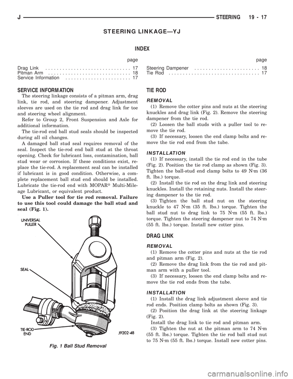
Use a Puller tool for tie rod removal. Failure
to use this tool could damage the ball stud and
seal (Fig. 1).
TIE ROD
REMOVAL
(1) Remove the cotter pins and nuts at the steering
knuckles and drag link (Fig. 2). Remove the steering
dampener from the tie rod.
(2) Loosen the ball studs with a puller tool to re-
move the tie rod.
(3) If necessary, loosen the end clamp bolts and re-
move the tie rod end from the tube.
INSTALLATION
(1) If necessary, install the tie rod end in the tube
(Fig. 2). Position the tie rod clamp as shown (Fig. 3).
Tighten the ball-stud end clamp bolts to 49 Nzm (36
ft. lbs.) torque.
(2) Install the tie rod on the drag link and steering
knuckles. Install the retaining nuts. Install the steer-
ing dampener to the tie rod.
(3) Tighten the ball stud nut on the steering
knuckle to 47 Nzm (35 ft. lbs.) torque. Tighten the
ball stud nut to drag link to 75 Nzm (55 ft. lbs.)
torque. Tighten the steering dampener nut to 74 Nzm
(55 ft. lbs.) torque. Install new cotter pins.
DRAG LINK
REMOVAL
(1) Remove the cotter pins and nuts at the tie rod
and pitman arm (Fig. 2).
(2) Remove the drag link from the tie rod and pit-
man arm with a puller tool.
(3) If necessary, loosen the end clamp bolts and re-
move the tie rod ends from the tube.
INSTALLATION
(1) Install the drag link adjustment sleeve and tie
rod ends. Position clamp bolts as shown (Fig. 3).
(2) Position the drag link at the steering linkage
(Fig. 2).
Install the drag link to tie rod and pitman arm.
(3) Tighten the nut at the pitman arm to 74 Nzm
(55 ft. lbs.) torque. Tighten the tie rod ball stud nut
to 75 Nzm (55 ft. lbs.) torque. Install new cotter pins.
Fig. 1 Ball Stud Removal
JSTEERING 19 - 17
Page 1058 of 1784
PITMAN SHAFT SEALSÐIN CAR REPLACEMENT
REMOVAL
(1) Remove pitman arm from gear. Refer to Pit-
man Arm Removal in Steering Linkage.
(2) Clean exposed end of pitman shaft and housing.
Use a wire brush to clean the shaft splines.
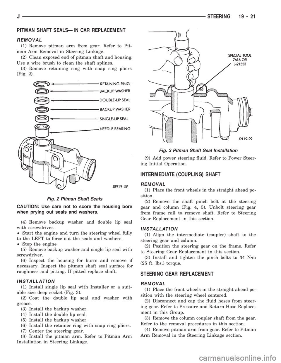
(3) Remove retaining ring with snap ring pliers
(Fig. 2).
CAUTION: Use care not to score the housing bore
when prying out seals and washers.
(4) Remove backup washer and double lip seal
with screwdriver.
²Start the engine and turn the steering wheel fully
to the LEFT to force out the seals and washers.
²Stop the engine
(5) Remove backup washer and single lip seal with
screwdriver.
(6) Inspect the housing for burrs and remove if
necessary. Inspect the pitman shaft seal surface for
roughness and pitting. If pitted replace shaft.
INSTALLATION
(1) Install single lip seal with Installer or a suit-
able size deep socket (Fig. 3).
(2) Coat the double lip seal and washer with
grease.
(3) Install the backup washer.
(4) Install the double lip seal.
(5) Install the backup washer.
(6) Install the retainer ring with snap ring pliers.
(7) Center the steering gear.
(8) Install the pitman arm. Refer to Pitman Arm
Installation in Steering Linkage.(9) Add power steering fluid. Refer to Power Steer-
ing Initial Operation.
INTERMEDIATE (COUPLING) SHAFT
REMOVAL
(1) Place the front wheels in the straight ahead po-
sition.
(2) Remove the shaft pinch bolt at the steering
gear and column (Fig. 4, 5). Unbolt steering gear
from frame rail to remove shaft. Refer to Steering
Gear Replacement in this section.
INSTALLATION
(1) Align the intermediate (coupler) shaft to the
steering gear and column.
(2) Position the steering gear on the frame. Refer
to Steering Gear Replacement in this section.
(3) Install and tighten the pinch bolts to 34 Nzm
(25 ft. lbs.) torque.
STEERING GEAR REPLACEMENT
REMOVAL
(1) Place the front wheels in the straight ahead po-
sition with the steering wheel centered.
(2) Disconnect and cap the fluid hoses from steer-
ing gear. Refer to Pressure and Return Hose Replace-
ment in this Group.
(3) Remove the column coupler shaft from the gear.
Refer to the removal procedures in this section.
(4) Remove pitman arm from gear. Refer to Pitman
Arm Removal in the Steering Linkage section.
Fig. 2 Pitman Shaft Seals
Fig. 3 Pitman Shaft Seal Installation
JSTEERING 19 - 21
Page 1074 of 1784
(2) Wrap a single layer of plastic tape around the
pitman shaft threads and splines. This will protect
the replacement seals during installation.
(3) Install the seal with a suitable size socket.
(4) Remove the tape from the shaft.
(5) Center the steering gear.
(6) Align and install the pitman arm.
(7) Install the washer and retaining nut on the pit-
man shaft. Tighten the nut to 251 Nb1m (185 ft. lbs.)
torque.
GEAR ADJUSTMENTS IN VEHICLE
REMOVE
(1) Raise and support the vehicle.
(2) Mark the pitman shaft and pitman arm for in-
stallation reference. Remove the pitman arm from
the shaft.
(3) Loosen the adjuster lock nut then back the ad-
juster plug off 1/4 turn.
(4) Remove the steering wheel horn pad.
(5) Turn the steering wheel in one direction until
stopped by the gear. Then turn back 1/2 turn.
CAUTION: Do not turn the steering wheel hard
against the internal stops when the linkage is re-
moved. This could result in damage to the recircu-
lating ball guides.
MEASURE
Place a low calibration (50 in. lbs.) torque wrench
and socket on the steering wheel nut. Rotate the
wrench and nut through a 90 degree arc (1/4 turn).
This will measure the worm shaft bearing preload.
ADJUST WORMSHAFT BEARING PRELOAD
TORQUE
(1) Adjust the preload by tightening the adjuster
plug. The preload should be 0.6 to 1 Nzm(5to8in.
lbs.) torque.
Steering column/shaft misalignment or damage will
increase the amount of torque required to rotate the
steering wheel. If the rotating torque is exceptionally
high, inspect the steering column/shaft alignment. If
the alignment is correct, remove the steering gear,
determine the cause of the high preload torque, and
repair as necessary.
(2) Tighten the adjuster locknut to 68 Nzm (50 ft.
lbs.) torque. Measure the preload torque. If neces-
sary, adjust the preload torque again.
ADJUST OVERCENTER DRAG TORQUE
(1) Turn the steering wheel from one stop to the
other and count the total numbers of turns. Turn the
wheel back in reverse direction 1/2 the total number
of turns to center the steering gear.
(2) Turn the over center adjusting screw in to re-
move all lash between the ball nut and pitman shaftsector teeth. Hold the adjustment screw and tighten
the lock nut to 34 Nzm (25 ft. lbs.) torque.
(3) Check the torque at the steering wheel by tak-
ing the highest reading as the wheel is turned
through the center position.
(4) The overcenter drag torque should be 0.5 to 1
Nzm (4 to 10 in. lbs.).
(5) If necessary, loosen the lock nut and adjust the
over center adjuster screw to obtain the proper
torque. Re-tighten the lock nut to the lock nut.
(6) After tightening the locknut, measure the over-
center drag torque again and readjust the torque, if
necessary.
INSTALL
(1) Align the installation reference marks and in-
stall the pitman arm.
(2) Install and tighten the pitman shaft nut and
washer to 251 Nzm (185 ft. lbs.) torque.
(3) Install the horn button.
GEAR DISASSEMBLY
(1) Rotate the wormshaft from stop-to-stop and
count the number of rotations. Rotate the wormshaft
in the reverse direction 1/2 of the total number of ro-
tations to center it and the ball nut.
(2) Remove the pitman shaft adjustment screw
locknut. Remove the cover retaining bolts, cover, and
gasket (Fig. 3).
(3) Slide the adjustment screw head (Fig. 3) out of
the pitman shaft T-slot and remove it and the
shim(s).
(4) Retain the shim(s) for end-play measurement
during assembly.
(5) Remove the pitman shaft, the wormshaft bear-
ing preload torque adjustment cap locknut, and the
adjustment cap (Fig. 2).
(6) Remove the wormshaft and the ball nut (Fig.
2).
(7) Remove (pry) the pitman shaft and the worm-
shaft seals from the steering gear housing (Fig. 3).
WORMSHAFT AND BALL NUT DISASSEMBLY
(1) Remove the upper bearing from the wormshaft
(Fig. 2).
CAUTION: Do not allow the ball nut to rotate freely
and travel to either extreme end of the wormshaft.
This could damage the tangs at the ends of the re-
circulating ball guides (Fig. 3).
(2) Remove the recirculating ball guide clamp re-
taining screws, the clamp and the guides (Fig. 2).
Separate the half-guides and place the recirculating
balls aside in a container.
(3) Hold the ball nut over a cloth. Remove the re-
maining recirculating balls by rotating the worm-
shaft back and forth.
JSTEERING 19 - 37
Page 1080 of 1784
INTERMEDIATE (COUPLER) SHAFT
REMOVAL
(1) Place the front wheels in the straight ahead po-
sition.
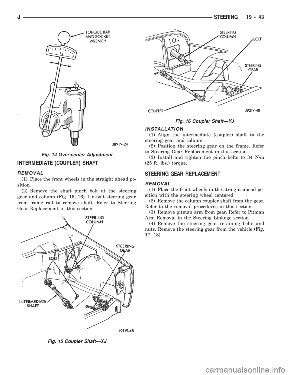
(2) Remove the shaft pinch bolt at the steering
gear and column (Fig. 15, 16). Un-bolt steering gear
from frame rail to remove shaft. Refer to Steering
Gear Replacement in this section.
INSTALLATION
(1) Align the intermediate (coupler) shaft to the
steering gear and column.
(2) Position the steering gear on the frame. Refer
to Steering Gear Replacement in this section.
(3) Install and tighten the pinch bolts to 34 Nzm
(25 ft. lbs.) torque.
STEERING GEAR REPLACEMENT
REMOVAL
(1) Place the front wheels in the straight ahead po-
sition with the steering wheel centered.
(2) Remove the column coupler shaft from the gear.
Refer to the removal procedures in this section.
(3) Remove pitman arm from gear. Refer to Pitman
Arm Removal in the Steering Linkage section.
(4) Remove the steering gear retaining bolts and
nuts. Remove the steering gear from the vehicle (Fig.
17, 18).
Fig. 14 Over-center Adjustment
Fig. 15 Coupler ShaftÐXJ
Fig. 16 Coupler ShaftÐYJ
JSTEERING 19 - 43