1994 JEEP CHEROKEE wheel bolts
[x] Cancel search: wheel boltsPage 1084 of 1784
(1) Make sure the front wheels are in thestraight
aheadposition.
(2) Disconnect the negative (ground) cable from
the battery.
(3) Remove steering wheel from column, refer to
Steering Wheel-Removal.
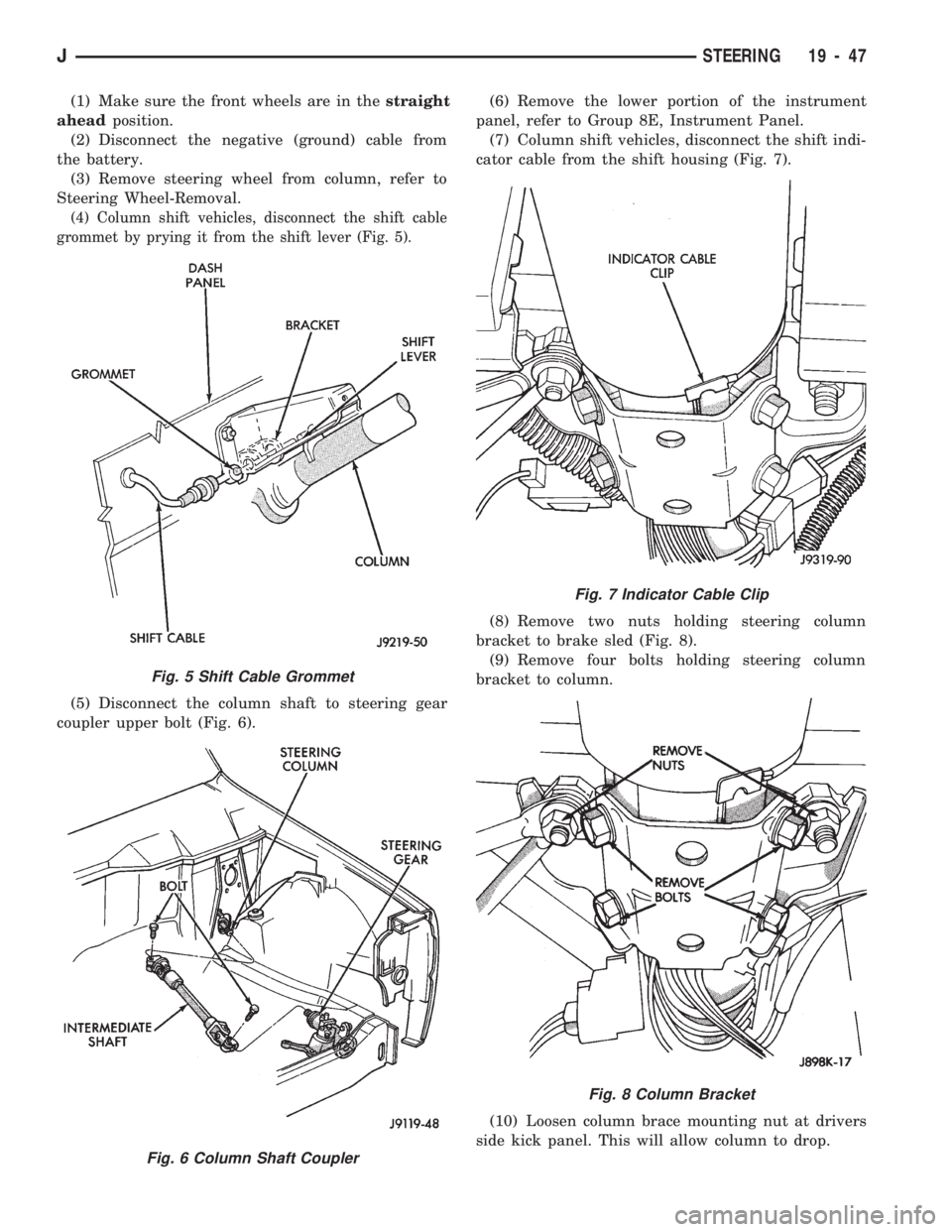
(4) Column shift vehicles, disconnect the shift cable
grommet by prying it from the shift lever (Fig. 5).
(5) Disconnect the column shaft to steering gear
coupler upper bolt (Fig. 6).(6) Remove the lower portion of the instrument
panel, refer to Group 8E, Instrument Panel.
(7) Column shift vehicles, disconnect the shift indi-
cator cable from the shift housing (Fig. 7).
(8) Remove two nuts holding steering column
bracket to brake sled (Fig. 8).
(9) Remove four bolts holding steering column
bracket to column.
(10) Loosen column brace mounting nut at drivers
side kick panel. This will allow column to drop.
Fig. 5 Shift Cable Grommet
Fig. 6 Column Shaft Coupler
Fig. 7 Indicator Cable Clip
Fig. 8 Column Bracket
JSTEERING 19 - 47
Page 1085 of 1784
(11) Disconnect the following items from the steer-
ing column connectors:
²Ignition switch wire harness
²Dimmer switch wire harness
²Turn signal switch wire harness
²Windshield wiper wire harness
²Cruise control wire harness (if equipped)
²Park-lock cable (if equipped)
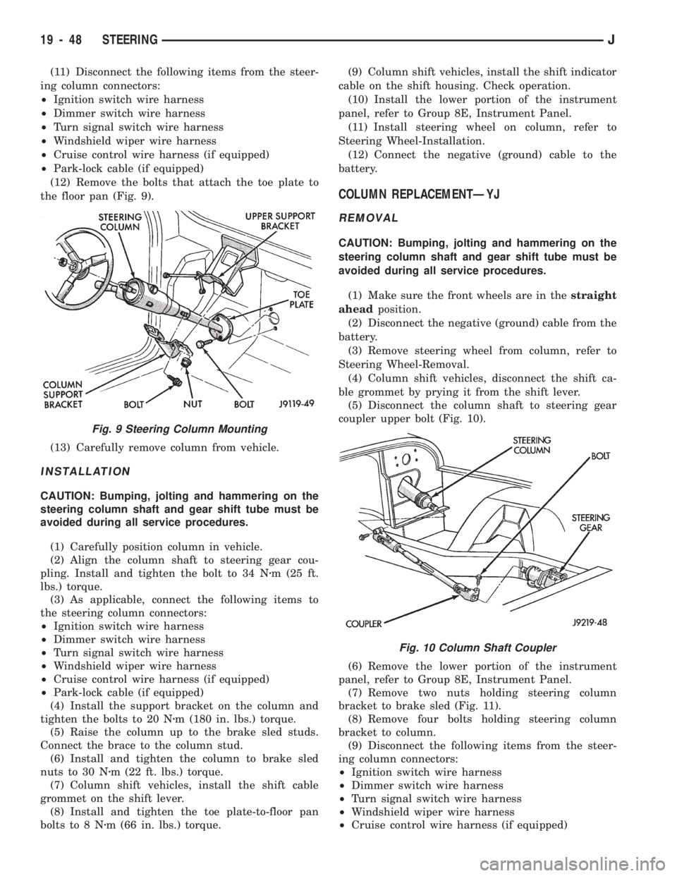
(12) Remove the bolts that attach the toe plate to
the floor pan (Fig. 9).
(13) Carefully remove column from vehicle.
INSTALLATION
CAUTION: Bumping, jolting and hammering on the
steering column shaft and gear shift tube must be
avoided during all service procedures.
(1) Carefully position column in vehicle.
(2) Align the column shaft to steering gear cou-
pling. Install and tighten the bolt to 34 Nzm (25 ft.
lbs.) torque.
(3) As applicable, connect the following items to
the steering column connectors:
²Ignition switch wire harness
²Dimmer switch wire harness
²Turn signal switch wire harness
²Windshield wiper wire harness
²Cruise control wire harness (if equipped)
²Park-lock cable (if equipped)
(4) Install the support bracket on the column and
tighten the bolts to 20 Nzm (180 in. lbs.) torque.
(5) Raise the column up to the brake sled studs.
Connect the brace to the column stud.
(6) Install and tighten the column to brake sled
nuts to 30 Nzm (22 ft. lbs.) torque.
(7) Column shift vehicles, install the shift cable
grommet on the shift lever.
(8) Install and tighten the toe plate-to-floor pan
bolts to 8 Nzm (66 in. lbs.) torque.(9) Column shift vehicles, install the shift indicator
cable on the shift housing. Check operation.
(10) Install the lower portion of the instrument
panel, refer to Group 8E, Instrument Panel.
(11) Install steering wheel on column, refer to
Steering Wheel-Installation.
(12) Connect the negative (ground) cable to the
battery.
COLUMN REPLACEMENTÐYJ
REMOVAL
CAUTION: Bumping, jolting and hammering on the
steering column shaft and gear shift tube must be
avoided during all service procedures.
(1) Make sure the front wheels are in thestraight
aheadposition.
(2) Disconnect the negative (ground) cable from the
battery.
(3) Remove steering wheel from column, refer to
Steering Wheel-Removal.
(4) Column shift vehicles, disconnect the shift ca-
ble grommet by prying it from the shift lever.
(5) Disconnect the column shaft to steering gear
coupler upper bolt (Fig. 10).
(6) Remove the lower portion of the instrument
panel, refer to Group 8E, Instrument Panel.
(7) Remove two nuts holding steering column
bracket to brake sled (Fig. 11).
(8) Remove four bolts holding steering column
bracket to column.
(9) Disconnect the following items from the steer-
ing column connectors:
²Ignition switch wire harness
²Dimmer switch wire harness
²Turn signal switch wire harness
²Windshield wiper wire harness
²Cruise control wire harness (if equipped)
Fig. 9 Steering Column Mounting
Fig. 10 Column Shaft Coupler
19 - 48 STEERINGJ
Page 1086 of 1784
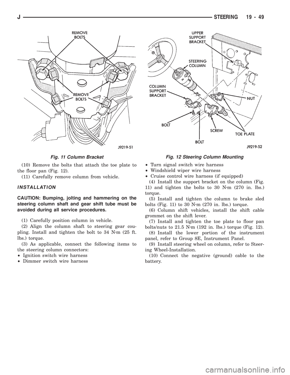
(10) Remove the bolts that attach the toe plate to
the floor pan (Fig. 12).
(11) Carefully remove column from vehicle.
INSTALLATION
CAUTION: Bumping, jolting and hammering on the
steering column shaft and gear shift tube must be
avoided during all service procedures.
(1) Carefully position column in vehicle.
(2) Align the column shaft to steering gear cou-
pling. Install and tighten the bolt to 34 Nzm (25 ft.
lbs.) torque.
(3) As applicable, connect the following items to
the steering column connectors:
²Ignition switch wire harness
²Dimmer switch wire harness²Turn signal switch wire harness
²Windshield wiper wire harness
²Cruise control wire harness (if equipped)
(4) Install the support bracket on the column (Fig.
11) and tighten the bolts to 30 Nzm (270 in. lbs.)
torque.
(5) Install and tighten the column to brake sled
bolts (Fig. 11) to 30 Nzm (270 in. lbs.) torque.
(6) Column shift vehicles, install the shift cable
grommet on the shift lever.
(7) Install and tighten the toe plate to floor pan
bolts/nuts to 21.5 Nzm (192 in. lbs.) torque (Fig. 12).
(8) Install the lower portion of the instrument
panel, refer to Group 8E, Instrument Panel.
(9) Install steering wheel on column, refer to Steer-
ing Wheel-Installation.
(10) Connect the negative (ground) cable to the
battery.
Fig. 11 Column BracketFig. 12 Steering Column Mounting
JSTEERING 19 - 49
Page 1116 of 1784
(12) Align transfer case and transmission shafts
and install transfer case. Tighten transfer case-to-
transmission nuts/bolts to 35 Nzm (26 ft. lbs.) torque.
(13) Remove jack stand from under engine and re-
position jack under transmission. Then remove trans-
mission jack.
(14) Connect transfer case vent hose and shift link-
age. Check and adjust linkage if necessary.
(15) Connect transmission and transfer case vent
hoses.
(16) Connect backup light switch wires.
(17) Connect vehicle speed sensor wires.
(18) Install and connect crankshaft position sensor
if equipped.
(19) Install rear crossmember, or skid plate (Fig. 5).
On XJ, tighten crossmember-to-frame bolts to 41 Nzm
(31 ft. lbs.) torque. Then tighten transmission-to-rear
support bolts/nuts to 45 Nzm (33 ft. lbs.) torque. On YJ,
tighten bolts/nuts to indicated torque (Fig. 5).
(20) Align and install front/rear propeller shafts.
Tighten shaft U-joint clamp bolts to 19 Nzm (170 in.
lbs.) torque.
(21) On XJ, install skid plate, if removed. Tighten
bolts to 42 Nzm (31 ft. lbs.) torque. Tighten stud nuts
to 17 Nzm (150 in. lbs.) torque.
(22) Top off transmission and transfer case lubri-
cant levels.
(23) Lower vehicle.
TRANSMISSION DISASSEMBLY AND OVERHAUL
ADAPTER HOUSING AND FRONT BEARING
RETAINER REMOVAL
(1) Drain transmission lubricant.
(2) Remove concentric bearing.
(3) Remove clutch housing bolts and remove housing.
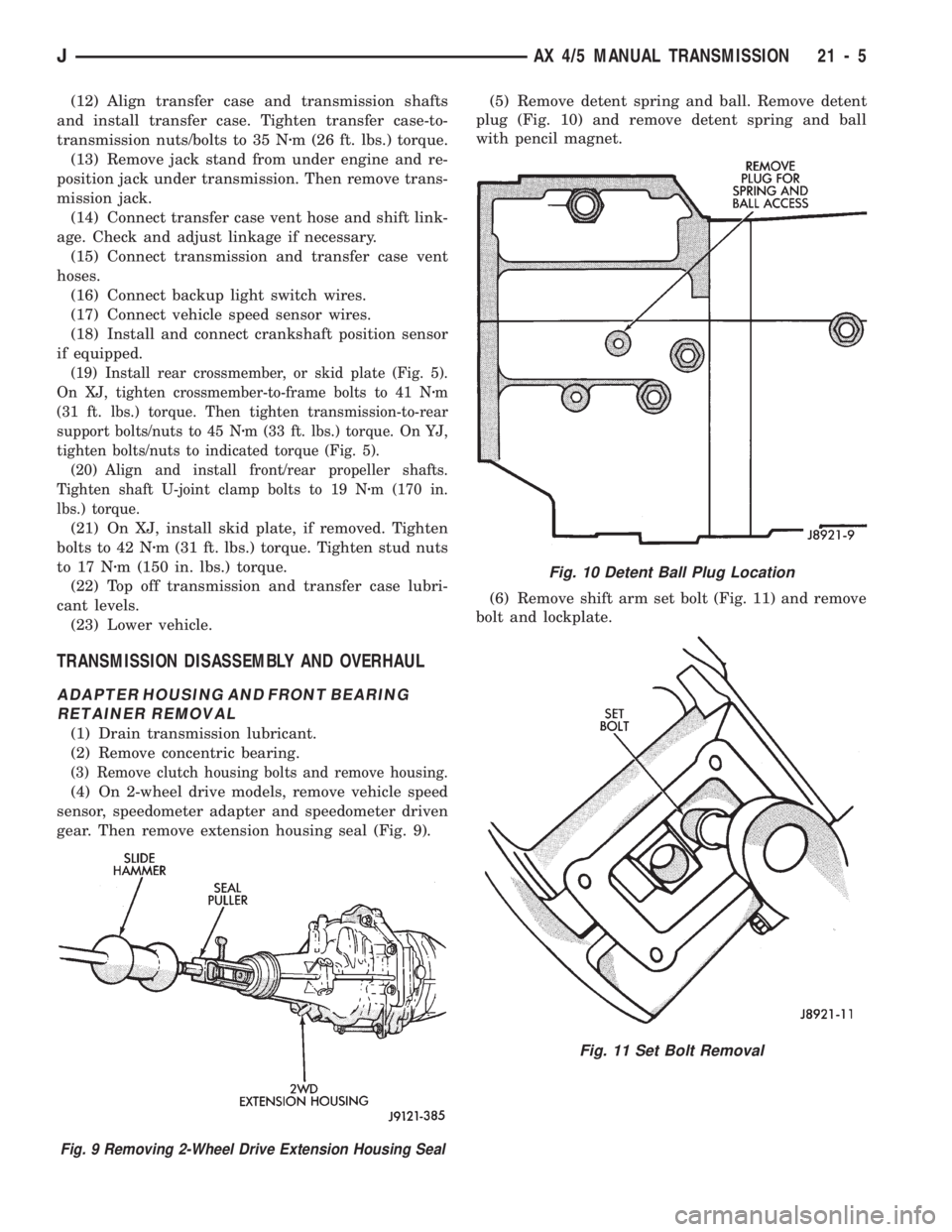
(4) On 2-wheel drive models, remove vehicle speed
sensor, speedometer adapter and speedometer driven
gear. Then remove extension housing seal (Fig. 9).(5) Remove detent spring and ball. Remove detent
plug (Fig. 10) and remove detent spring and ball
with pencil magnet.
(6) Remove shift arm set bolt (Fig. 11) and remove
bolt and lockplate.
Fig. 10 Detent Ball Plug Location
Fig. 11 Set Bolt Removal
Fig. 9 Removing 2-Wheel Drive Extension Housing Seal
JAX 4/5 MANUAL TRANSMISSION 21 - 5
Page 1141 of 1784
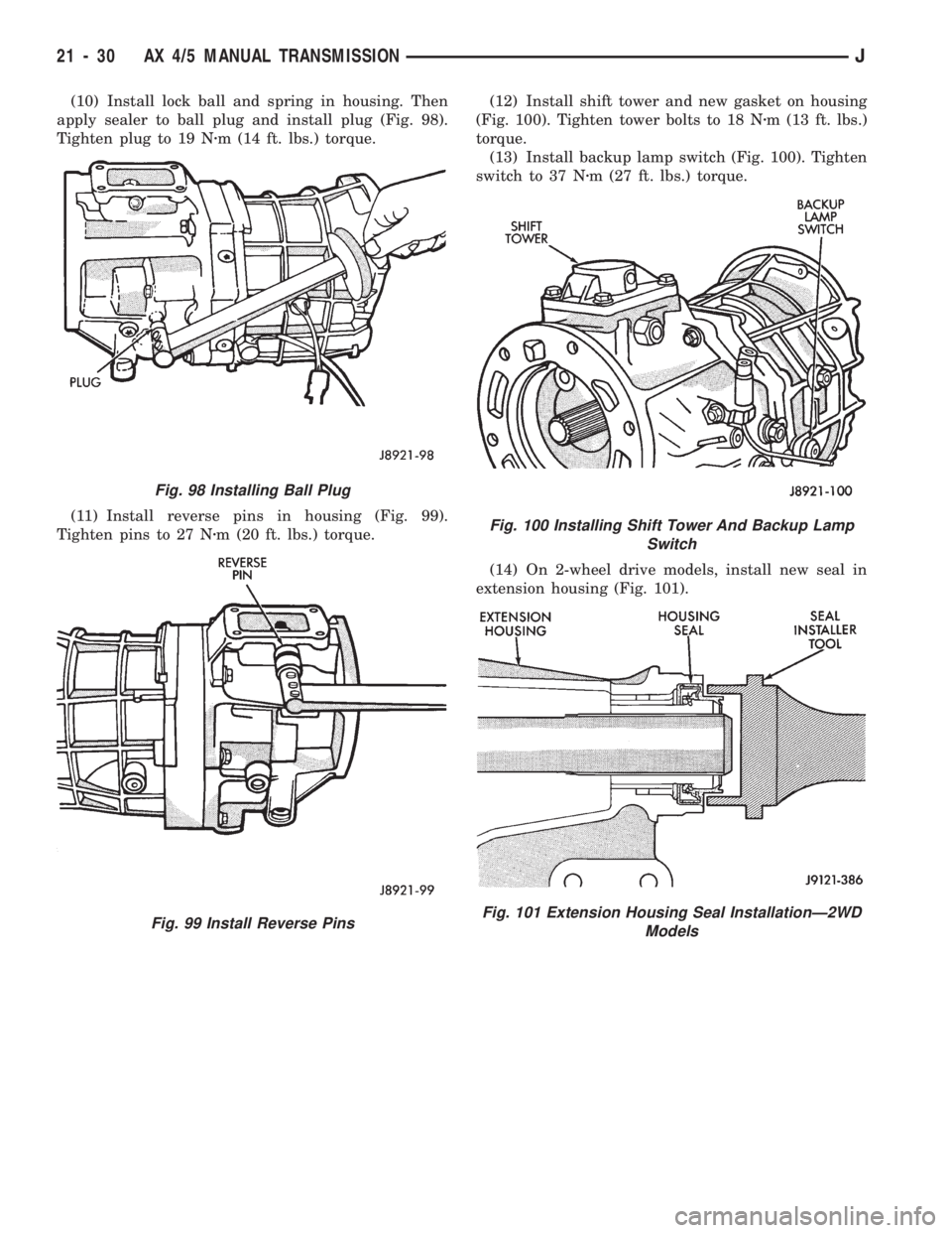
(10) Install lock ball and spring in housing. Then
apply sealer to ball plug and install plug (Fig. 98).
Tighten plug to 19 Nzm (14 ft. lbs.) torque.
(11) Install reverse pins in housing (Fig. 99).
Tighten pins to 27 Nzm (20 ft. lbs.) torque.(12) Install shift tower and new gasket on housing
(Fig. 100). Tighten tower bolts to 18 Nzm (13 ft. lbs.)
torque.
(13) Install backup lamp switch (Fig. 100). Tighten
switch to 37 Nzm (27 ft. lbs.) torque.
(14) On 2-wheel drive models, install new seal in
extension housing (Fig. 101).
Fig. 98 Installing Ball Plug
Fig. 99 Install Reverse Pins
Fig. 100 Installing Shift Tower And Backup Lamp
Switch
Fig. 101 Extension Housing Seal InstallationÐ2WD
Models
21 - 30 AX 4/5 MANUAL TRANSMISSIONJ
Page 1147 of 1784
(10) Remove jack from under transmission and
mount transfer case on jack.
(11) Align transfer case and transmission shafts
and install transfer case. Tighten transfer case-to-
transmission nuts/bolts to 35 Nzm (26 ft. lbs.) torque.
(12) Move jack stand from under engine and repo-
sition it under transmission. Then remove transmis-
sion jack.
(13) Connect transfer case vacuum hoses and link-
age. Check and adjust linkage if necessary.
(14) Connect transmission and transfer case vent
hoses and backup light switch wires.
(15) Install clutch sleeve cylinder.
(16) Connect vehicle speed sensor and wires.
(17) On XJ, install rear crossmember and attach
cushion and bracket. Tighten crossmember-to-frame
bolts to 41 Nzm (30 ft. lbs.) torque. Tighten transmis-
sion-to-rear cushion and bracket bolts/nuts to 45 Nzm
(33 ft. lbs.) torque.
(18) On YJ, install rear cushion and bracket and
skid plate. Tighten attaching bolts/nuts to indicated
torque (Fig. 1).
(19) Align and install front/rear propeller shafts.
Tighten shaft U-joint clamp bolts to 19 Nzm (170 in.
lbs.) torque.
(20) On XJ, install skid plate if removed. Tighten
bolts to 42 Nzm (31 ft. lbs.) torque. Tighten stud nuts
to 17 Nzm (150 in. lbs.) torque.
(21) Top off transmission and transfer lubricant
levels.
(22) Remove supports and lower vehicle.
TRANSMISSION DISASSEMBLY AND OVERHAUL
ADAPTER/EXTENSION HOUSING REMOVAL
(1) Remove release bearing, fork, retainer clip and
clutch housing from transmission. Also remove shift
lever if not previously removed.
(2) On 2-wheel drive models, remove extension
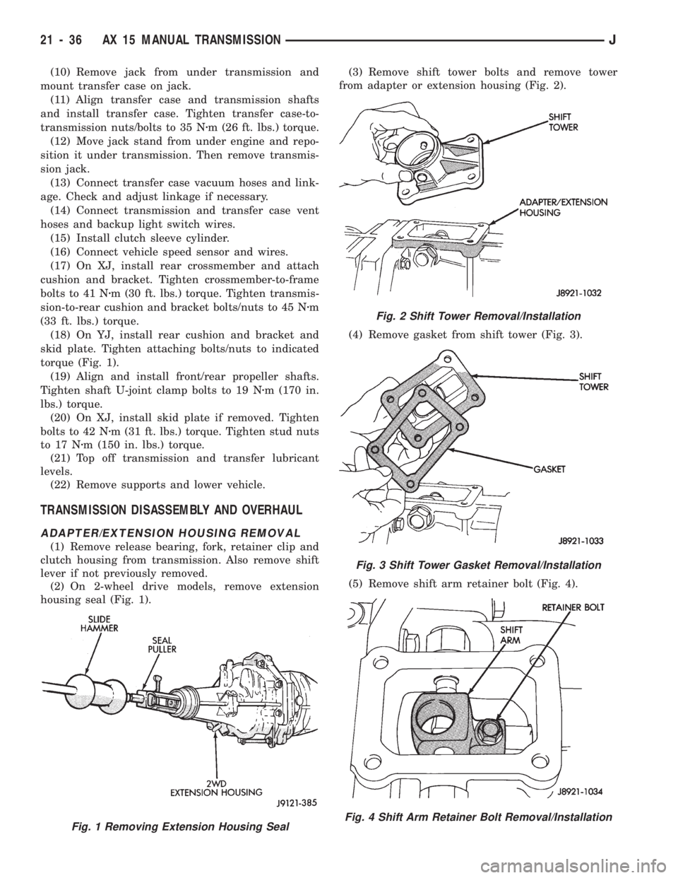
housing seal (Fig. 1).(3) Remove shift tower bolts and remove tower
from adapter or extension housing (Fig. 2).
(4) Remove gasket from shift tower (Fig. 3).
(5) Remove shift arm retainer bolt (Fig. 4).
Fig. 1 Removing Extension Housing Seal
Fig. 2 Shift Tower Removal/Installation
Fig. 3 Shift Tower Gasket Removal/Installation
Fig. 4 Shift Arm Retainer Bolt Removal/Installation
21 - 36 AX 15 MANUAL TRANSMISSIONJ
Page 1149 of 1784
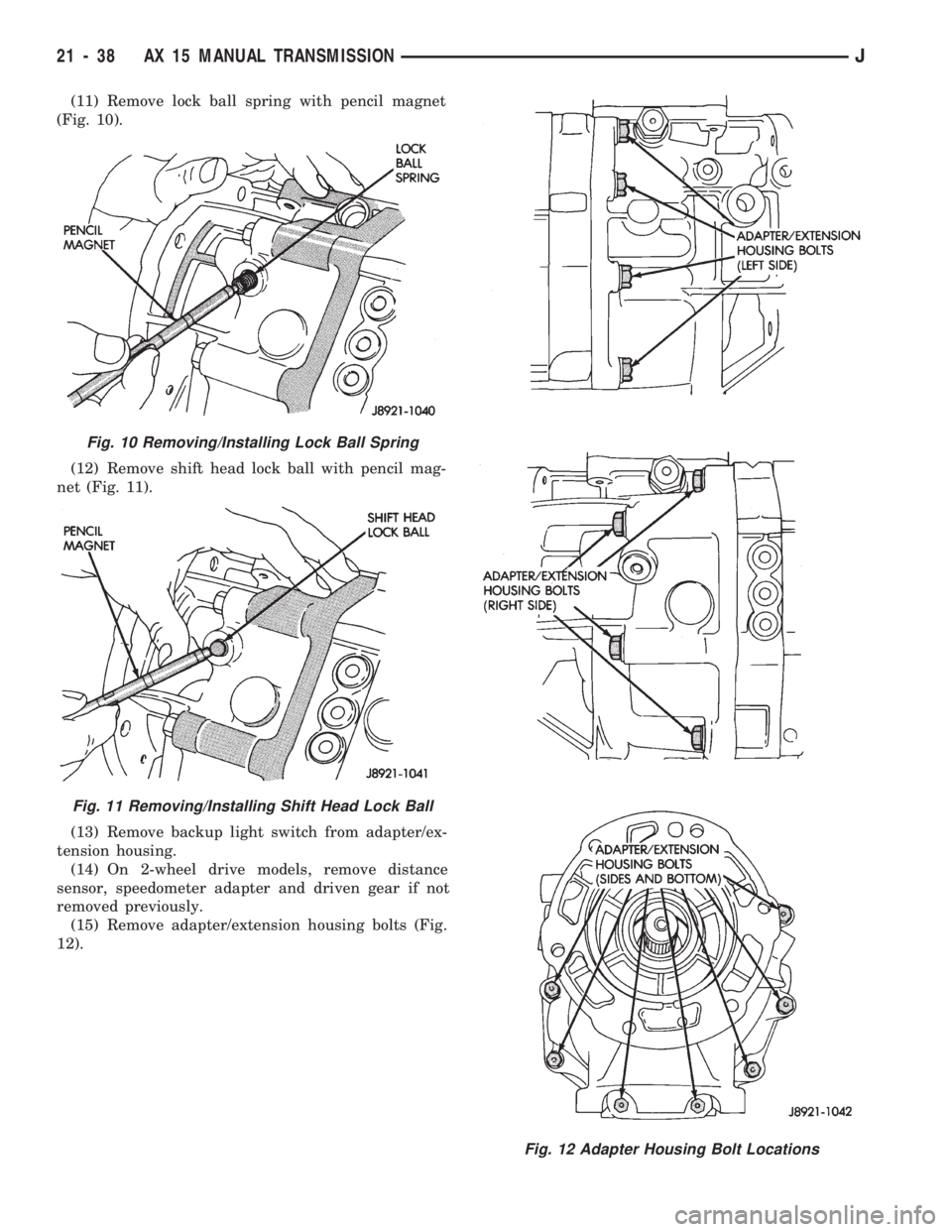
(11) Remove lock ball spring with pencil magnet
(Fig. 10).
(12) Remove shift head lock ball with pencil mag-
net (Fig. 11).
(13) Remove backup light switch from adapter/ex-
tension housing.
(14) On 2-wheel drive models, remove distance
sensor, speedometer adapter and driven gear if not
removed previously.
(15) Remove adapter/extension housing bolts (Fig.
12).
Fig. 10 Removing/Installing Lock Ball Spring
Fig. 11 Removing/Installing Shift Head Lock Ball
Fig. 12 Adapter Housing Bolt Locations
21 - 38 AX 15 MANUAL TRANSMISSIONJ
Page 1173 of 1784
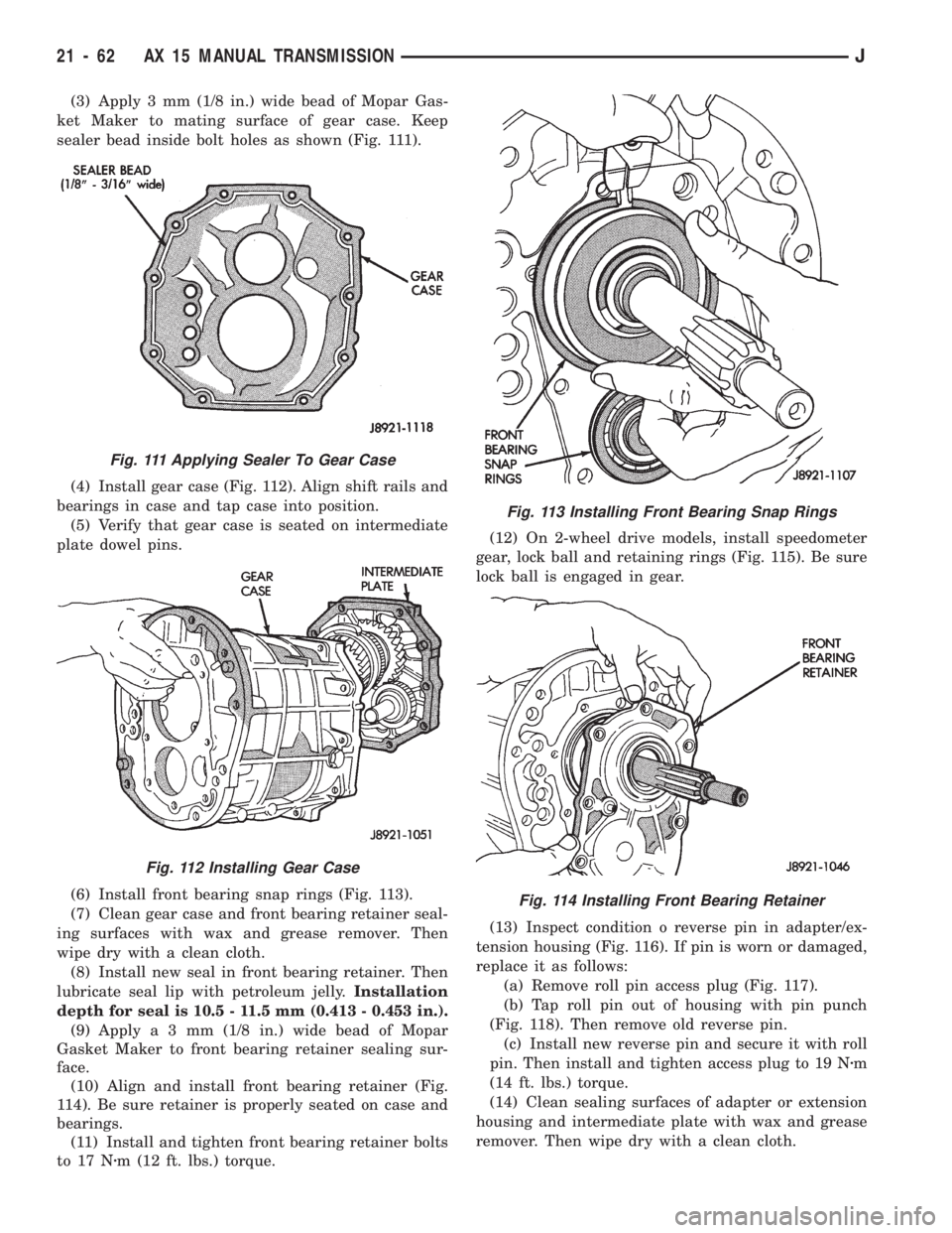
(3) Apply 3 mm (1/8 in.) wide bead of Mopar Gas-
ket Maker to mating surface of gear case. Keep
sealer bead inside bolt holes as shown (Fig. 111).
(4) Install gear case (Fig. 112). Align shift rails and
bearings in case and tap case into position.
(5) Verify that gear case is seated on intermediate
plate dowel pins.
(6) Install front bearing snap rings (Fig. 113).
(7) Clean gear case and front bearing retainer seal-
ing surfaces with wax and grease remover. Then
wipe dry with a clean cloth.
(8) Install new seal in front bearing retainer. Then
lubricate seal lip with petroleum jelly.Installation
depth for seal is 10.5 - 11.5 mm (0.413 - 0.453 in.).
(9) Applya3mm(1/8 in.) wide bead of Mopar
Gasket Maker to front bearing retainer sealing sur-
face.
(10) Align and install front bearing retainer (Fig.
114). Be sure retainer is properly seated on case and
bearings.
(11) Install and tighten front bearing retainer bolts
to 17 Nzm (12 ft. lbs.) torque.(12) On 2-wheel drive models, install speedometer
gear, lock ball and retaining rings (Fig. 115). Be sure
lock ball is engaged in gear.
(13) Inspect condition o reverse pin in adapter/ex-
tension housing (Fig. 116). If pin is worn or damaged,
replace it as follows:
(a) Remove roll pin access plug (Fig. 117).
(b) Tap roll pin out of housing with pin punch
(Fig. 118). Then remove old reverse pin.
(c) Install new reverse pin and secure it with roll
pin. Then install and tighten access plug to 19 Nzm
(14 ft. lbs.) torque.
(14) Clean sealing surfaces of adapter or extension
housing and intermediate plate with wax and grease
remover. Then wipe dry with a clean cloth.
Fig. 111 Applying Sealer To Gear Case
Fig. 112 Installing Gear Case
Fig. 113 Installing Front Bearing Snap Rings
Fig. 114 Installing Front Bearing Retainer
21 - 62 AX 15 MANUAL TRANSMISSIONJ