1994 JEEP CHEROKEE ECU
[x] Cancel search: ECUPage 1387 of 1784
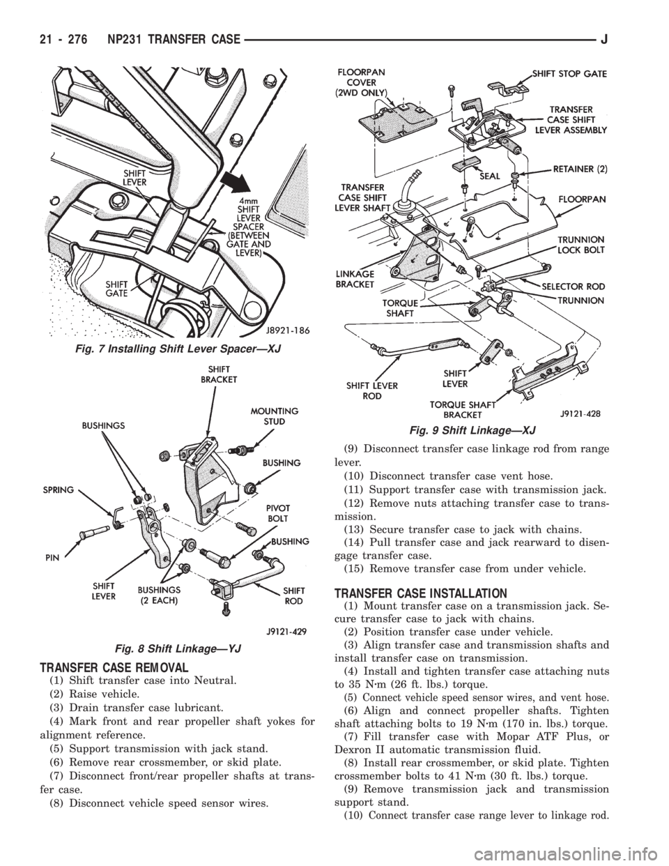
TRANSFER CASE REMOVAL
(1) Shift transfer case into Neutral.
(2) Raise vehicle.
(3) Drain transfer case lubricant.
(4) Mark front and rear propeller shaft yokes for
alignment reference.
(5) Support transmission with jack stand.
(6) Remove rear crossmember, or skid plate.
(7) Disconnect front/rear propeller shafts at trans-
fer case.
(8) Disconnect vehicle speed sensor wires.(9) Disconnect transfer case linkage rod from range
lever.
(10) Disconnect transfer case vent hose.
(11) Support transfer case with transmission jack.
(12) Remove nuts attaching transfer case to trans-
mission.
(13) Secure transfer case to jack with chains.
(14) Pull transfer case and jack rearward to disen-
gage transfer case.
(15) Remove transfer case from under vehicle.
TRANSFER CASE INSTALLATION
(1) Mount transfer case on a transmission jack. Se-
cure transfer case to jack with chains.
(2) Position transfer case under vehicle.
(3) Align transfer case and transmission shafts and
install transfer case on transmission.
(4) Install and tighten transfer case attaching nuts
to 35 Nzm (26 ft. lbs.) torque.
(5) Connect vehicle speed sensor wires, and vent hose.
(6) Align and connect propeller shafts. Tighten
shaft attaching bolts to 19 Nzm (170 in. lbs.) torque.
(7) Fill transfer case with Mopar ATF Plus, or
Dexron II automatic transmission fluid.
(8) Install rear crossmember, or skid plate. Tighten
crossmember bolts to 41 Nzm (30 ft. lbs.) torque.
(9) Remove transmission jack and transmission
support stand.
(10) Connect transfer case range lever to linkage rod.
Fig. 7 Installing Shift Lever SpacerÐXJ
Fig. 8 Shift LinkageÐYJ
Fig. 9 Shift LinkageÐXJ
21 - 276 NP231 TRANSFER CASEJ
Page 1393 of 1784
CLEANING AND INSPECTION
Clean the transfer case components thoroughly
with solvent. Remove all traces of sealer from the
case and retainer seal surfaces.Clean the oil pickup screen with solvent and dry it
with compressed air. Also use compressed air to re-
move solvent residue from all oil feed passages and
channels.
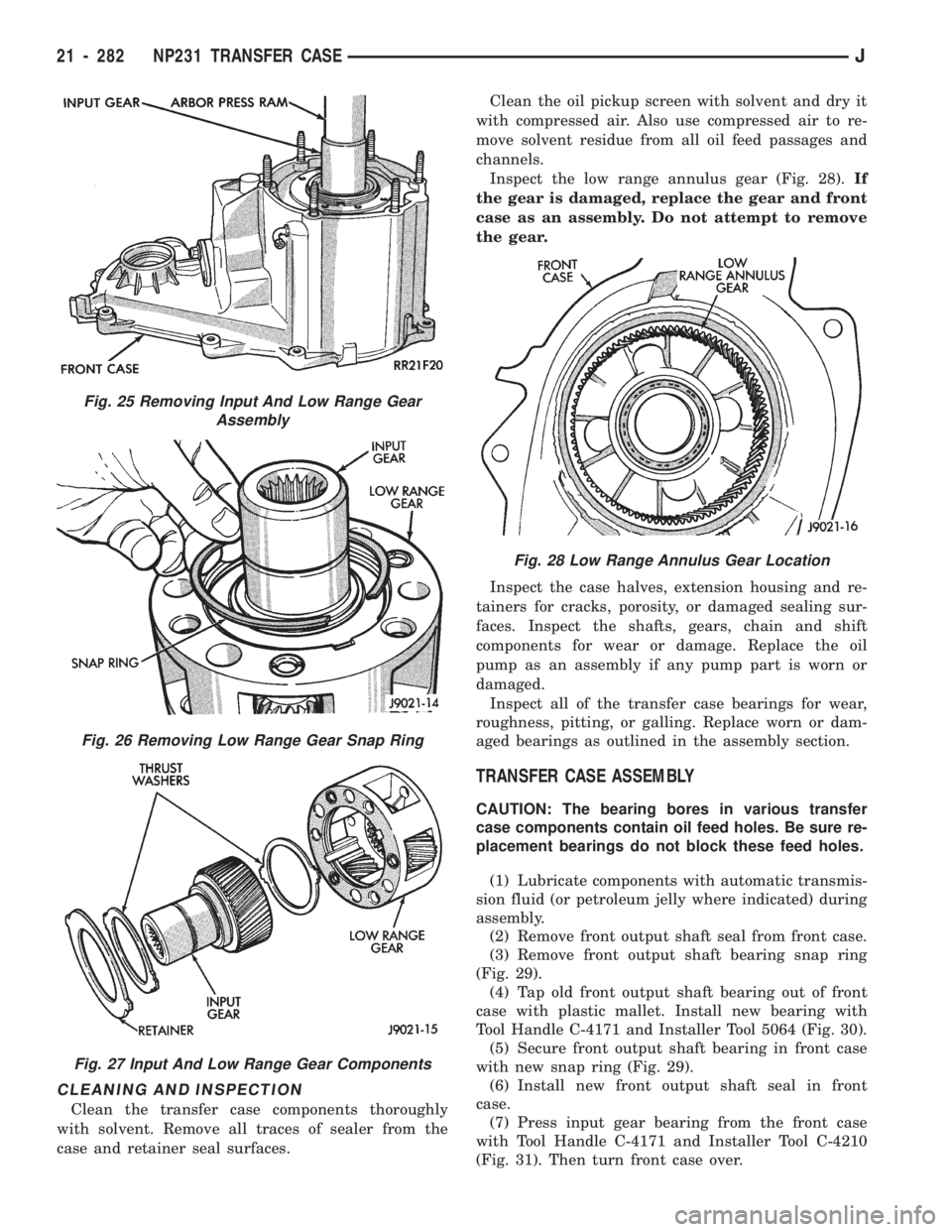
Inspect the low range annulus gear (Fig. 28).If
the gear is damaged, replace the gear and front
case as an assembly. Do not attempt to remove
the gear.
Inspect the case halves, extension housing and re-
tainers for cracks, porosity, or damaged sealing sur-
faces. Inspect the shafts, gears, chain and shift
components for wear or damage. Replace the oil
pump as an assembly if any pump part is worn or
damaged.
Inspect all of the transfer case bearings for wear,
roughness, pitting, or galling. Replace worn or dam-
aged bearings as outlined in the assembly section.
TRANSFER CASE ASSEMBLY
CAUTION: The bearing bores in various transfer
case components contain oil feed holes. Be sure re-
placement bearings do not block these feed holes.
(1) Lubricate components with automatic transmis-
sion fluid (or petroleum jelly where indicated) during
assembly.
(2) Remove front output shaft seal from front case.
(3) Remove front output shaft bearing snap ring
(Fig. 29).
(4) Tap old front output shaft bearing out of front
case with plastic mallet. Install new bearing with
Tool Handle C-4171 and Installer Tool 5064 (Fig. 30).
(5) Secure front output shaft bearing in front case
with new snap ring (Fig. 29).
(6) Install new front output shaft seal in front
case.
(7) Press input gear bearing from the front case
with Tool Handle C-4171 and Installer Tool C-4210
(Fig. 31). Then turn front case over.
Fig. 25 Removing Input And Low Range Gear
Assembly
Fig. 26 Removing Low Range Gear Snap Ring
Fig. 27 Input And Low Range Gear Components
Fig. 28 Low Range Annulus Gear Location
21 - 282 NP231 TRANSFER CASEJ
Page 1396 of 1784
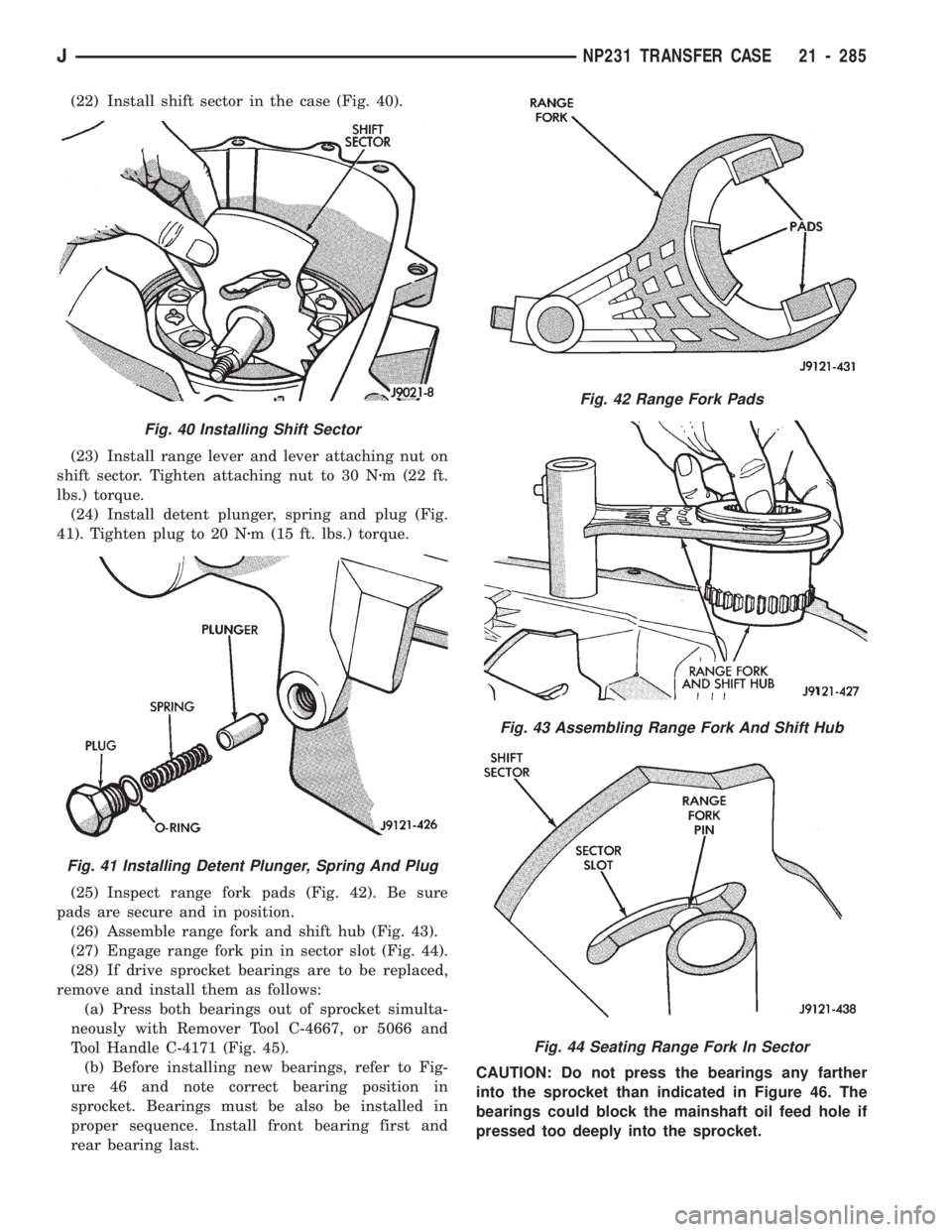
(22) Install shift sector in the case (Fig. 40).
(23) Install range lever and lever attaching nut on
shift sector. Tighten attaching nut to 30 Nzm (22 ft.
lbs.) torque.
(24) Install detent plunger, spring and plug (Fig.
41). Tighten plug to 20 Nzm (15 ft. lbs.) torque.
(25) Inspect range fork pads (Fig. 42). Be sure
pads are secure and in position.
(26) Assemble range fork and shift hub (Fig. 43).
(27) Engage range fork pin in sector slot (Fig. 44).
(28) If drive sprocket bearings are to be replaced,
remove and install them as follows:
(a) Press both bearings out of sprocket simulta-
neously with Remover Tool C-4667, or 5066 and
Tool Handle C-4171 (Fig. 45).
(b) Before installing new bearings, refer to Fig-
ure 46 and note correct bearing position in
sprocket. Bearings must be also be installed in
proper sequence. Install front bearing first and
rear bearing last.CAUTION: Do not press the bearings any farther
into the sprocket than indicated in Figure 46. The
bearings could block the mainshaft oil feed hole if
pressed too deeply into the sprocket.
Fig. 42 Range Fork Pads
Fig. 43 Assembling Range Fork And Shift Hub
Fig. 44 Seating Range Fork In Sector
Fig. 40 Installing Shift Sector
Fig. 41 Installing Detent Plunger, Spring And Plug
JNP231 TRANSFER CASE 21 - 285
Page 1401 of 1784
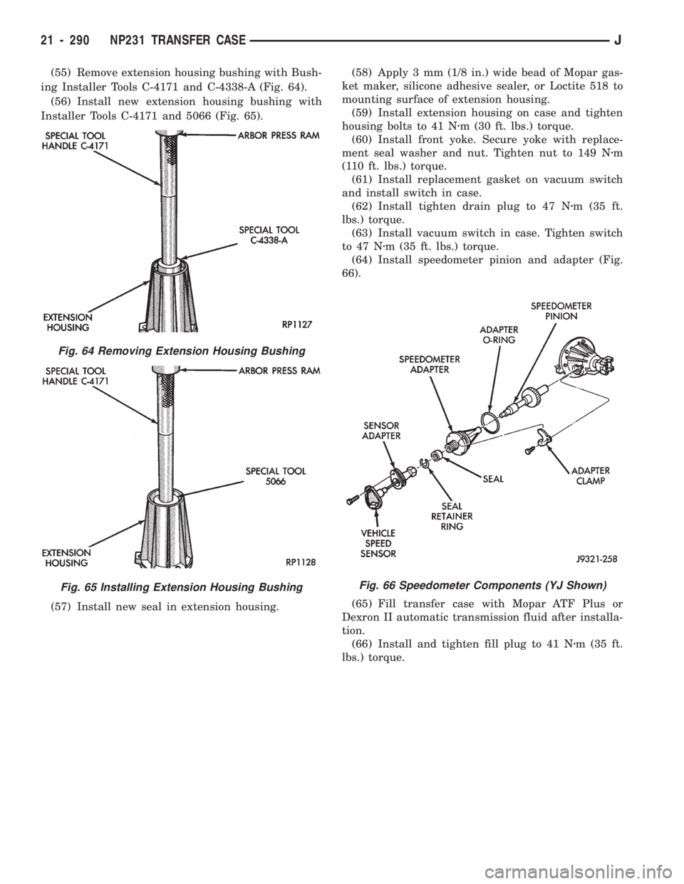
(55) Remove extension housing bushing with Bush-
ing Installer Tools C-4171 and C-4338-A (Fig. 64).
(56) Install new extension housing bushing with
Installer Tools C-4171 and 5066 (Fig. 65).
(57) Install new seal in extension housing.(58) Apply 3 mm (1/8 in.) wide bead of Mopar gas-
ket maker, silicone adhesive sealer, or Loctite 518 to
mounting surface of extension housing.
(59) Install extension housing on case and tighten
housing bolts to 41 Nzm (30 ft. lbs.) torque.
(60) Install front yoke. Secure yoke with replace-
ment seal washer and nut. Tighten nut to 149 Nzm
(110 ft. lbs.) torque.
(61) Install replacement gasket on vacuum switch
and install switch in case.
(62) Install tighten drain plug to 47 Nzm (35 ft.
lbs.) torque.
(63) Install vacuum switch in case. Tighten switch
to 47 Nzm (35 ft. lbs.) torque.
(64) Install speedometer pinion and adapter (Fig.
66).
(65) Fill transfer case with Mopar ATF Plus or
Dexron II automatic transmission fluid after installa-
tion.
(66) Install and tighten fill plug to 41 Nzm (35 ft.
lbs.) torque.
Fig. 64 Removing Extension Housing Bushing
Fig. 65 Installing Extension Housing BushingFig. 66 Speedometer Components (YJ Shown)
21 - 290 NP231 TRANSFER CASEJ
Page 1407 of 1784
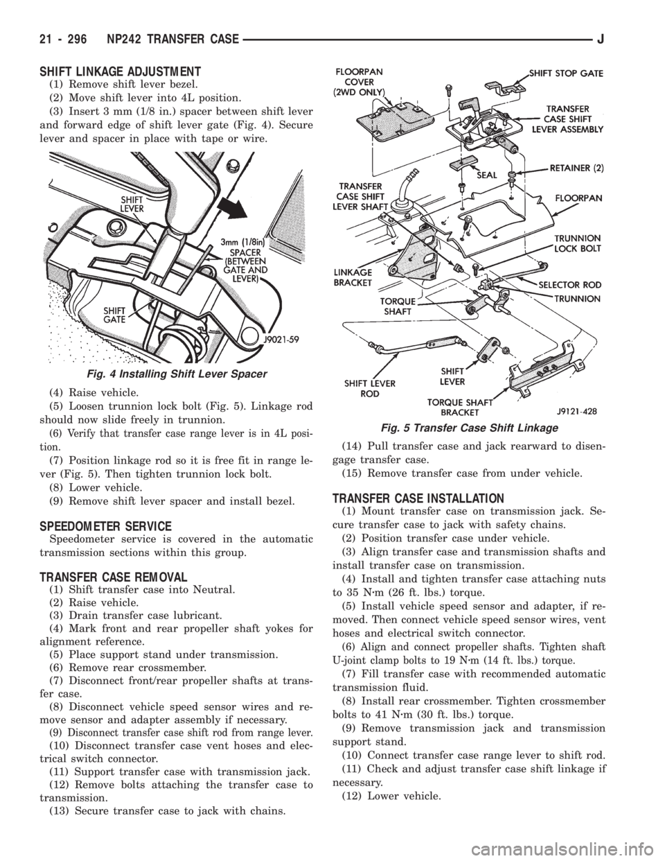
SHIFT LINKAGE ADJUSTMENT
(1) Remove shift lever bezel.
(2) Move shift lever into 4L position.
(3) Insert 3 mm (1/8 in.) spacer between shift lever
and forward edge of shift lever gate (Fig. 4). Secure
lever and spacer in place with tape or wire.
(4) Raise vehicle.
(5) Loosen trunnion lock bolt (Fig. 5). Linkage rod
should now slide freely in trunnion.
(6) Verify that transfer case range lever is in 4L posi-
tion.
(7) Position linkage rod so it is free fit in range le-
ver (Fig. 5). Then tighten trunnion lock bolt.
(8) Lower vehicle.
(9) Remove shift lever spacer and install bezel.
SPEEDOMETER SERVICE
Speedometer service is covered in the automatic
transmission sections within this group.
TRANSFER CASE REMOVAL
(1) Shift transfer case into Neutral.
(2) Raise vehicle.
(3) Drain transfer case lubricant.
(4) Mark front and rear propeller shaft yokes for
alignment reference.
(5) Place support stand under transmission.
(6) Remove rear crossmember.
(7) Disconnect front/rear propeller shafts at trans-
fer case.
(8) Disconnect vehicle speed sensor wires and re-
move sensor and adapter assembly if necessary.
(9) Disconnect transfer case shift rod from range lever.
(10) Disconnect transfer case vent hoses and elec-
trical switch connector.
(11) Support transfer case with transmission jack.
(12) Remove bolts attaching the transfer case to
transmission.
(13) Secure transfer case to jack with chains.(14) Pull transfer case and jack rearward to disen-
gage transfer case.
(15) Remove transfer case from under vehicle.
TRANSFER CASE INSTALLATION
(1) Mount transfer case on transmission jack. Se-
cure transfer case to jack with safety chains.
(2) Position transfer case under vehicle.
(3) Align transfer case and transmission shafts and
install transfer case on transmission.
(4) Install and tighten transfer case attaching nuts
to 35 Nzm (26 ft. lbs.) torque.
(5) Install vehicle speed sensor and adapter, if re-
moved. Then connect vehicle speed sensor wires, vent
hoses and electrical switch connector.
(6) Align and connect propeller shafts. Tighten shaft
U-joint clamp bolts to 19 Nzm (14 ft. lbs.) torque.
(7) Fill transfer case with recommended automatic
transmission fluid.
(8) Install rear crossmember. Tighten crossmember
bolts to 41 Nzm (30 ft. lbs.) torque.
(9) Remove transmission jack and transmission
support stand.
(10) Connect transfer case range lever to shift rod.
(11) Check and adjust transfer case shift linkage if
necessary.
(12) Lower vehicle.
Fig. 4 Installing Shift Lever Spacer
Fig. 5 Transfer Case Shift Linkage
21 - 296 NP242 TRANSFER CASEJ
Page 1424 of 1784
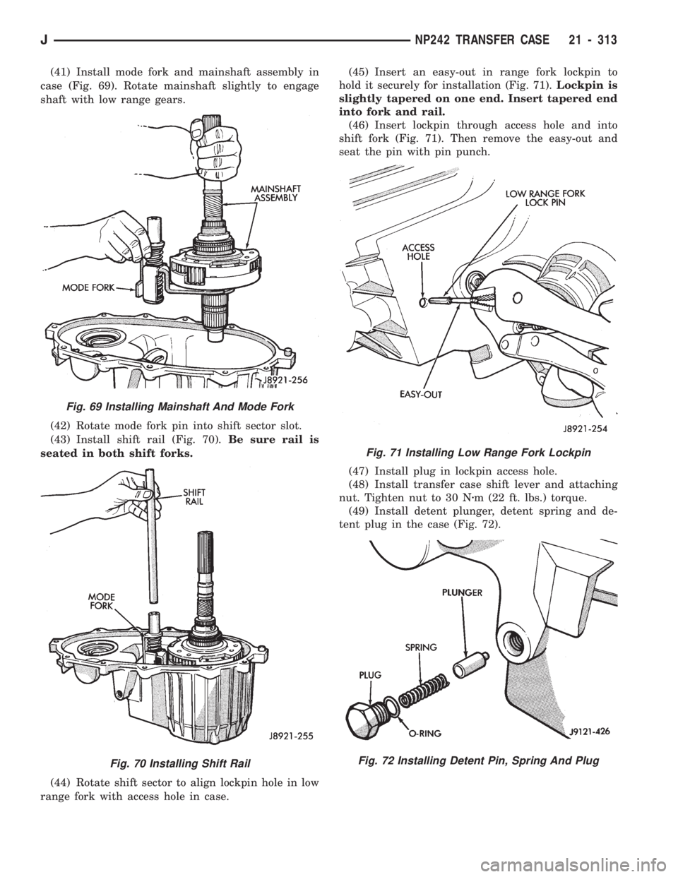
(41) Install mode fork and mainshaft assembly in
case (Fig. 69). Rotate mainshaft slightly to engage
shaft with low range gears.
(42) Rotate mode fork pin into shift sector slot.
(43) Install shift rail (Fig. 70).Be sure rail is
seated in both shift forks.
(44) Rotate shift sector to align lockpin hole in low
range fork with access hole in case.(45) Insert an easy-out in range fork lockpin to
hold it securely for installation (Fig. 71).Lockpin is
slightly tapered on one end. Insert tapered end
into fork and rail.
(46) Insert lockpin through access hole and into
shift fork (Fig. 71). Then remove the easy-out and
seat the pin with pin punch.
(47) Install plug in lockpin access hole.
(48) Install transfer case shift lever and attaching
nut. Tighten nut to 30 Nzm (22 ft. lbs.) torque.
(49) Install detent plunger, detent spring and de-
tent plug in the case (Fig. 72).
Fig. 69 Installing Mainshaft And Mode Fork
Fig. 70 Installing Shift Rail
Fig. 71 Installing Low Range Fork Lockpin
Fig. 72 Installing Detent Pin, Spring And Plug
JNP242 TRANSFER CASE 21 - 313
Page 1428 of 1784
(72) Apply 3 mm (1/8 in.) wide bead of Mopar gas-
ket maker, silicone adhesive sealer, or Loctite 518 to
seal surface of extension housing.
(73) Install extension housing on case. Tighten
housing bolts to 41 Nzm (30 ft. lbs.) torque.
(74) Install front yoke. Secure yoke with new seal
washer and nut. Tighten nut to 149 Nzm (110 ft. lbs.)
torque.
(75) Install new gasket on vacuum switch and in-
stall switch in the case. Tighten switch to 27 Nzm (20
ft. lbs.) torque.
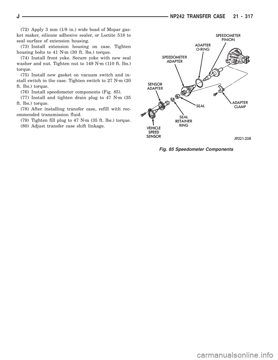
(76) Install speedometer components (Fig. 85).
(77) Install and tighten drain plug to 47 Nzm (35
ft. lbs.) torque.
(78) After installing transfer case, refill with rec-
ommended transmission fluid.
(79) Tighten fill plug to 47 Nzm (35 ft. lbs.) torque.
(80) Adjust transfer case shift linkage.
Fig. 85 Speedometer Components
JNP242 TRANSFER CASE 21 - 317
Page 1487 of 1784
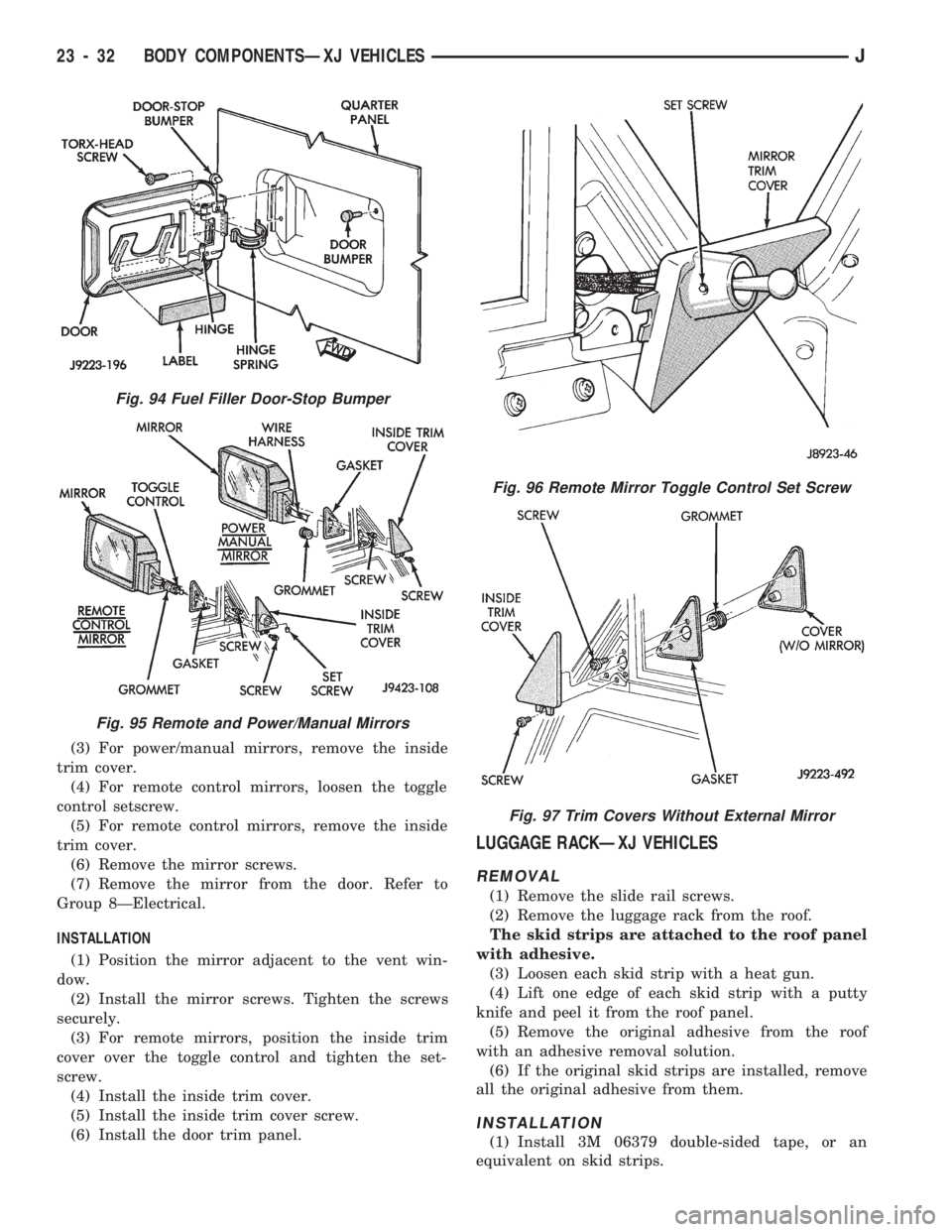
(3) For power/manual mirrors, remove the inside
trim cover.
(4) For remote control mirrors, loosen the toggle
control setscrew.
(5) For remote control mirrors, remove the inside
trim cover.
(6) Remove the mirror screws.
(7) Remove the mirror from the door. Refer to
Group 8ÐElectrical.
INSTALLATION
(1) Position the mirror adjacent to the vent win-
dow.
(2) Install the mirror screws. Tighten the screws
securely.
(3) For remote mirrors, position the inside trim
cover over the toggle control and tighten the set-
screw.
(4) Install the inside trim cover.
(5) Install the inside trim cover screw.
(6) Install the door trim panel.
LUGGAGE RACKÐXJ VEHICLES
REMOVAL
(1) Remove the slide rail screws.
(2) Remove the luggage rack from the roof.
The skid strips are attached to the roof panel
with adhesive.
(3) Loosen each skid strip with a heat gun.
(4) Lift one edge of each skid strip with a putty
knife and peel it from the roof panel.
(5) Remove the original adhesive from the roof
with an adhesive removal solution.
(6) If the original skid strips are installed, remove
all the original adhesive from them.
INSTALLATION
(1) Install 3M 06379 double-sided tape, or an
equivalent on skid strips.
Fig. 94 Fuel Filler Door-Stop Bumper
Fig. 95 Remote and Power/Manual Mirrors
Fig. 96 Remote Mirror Toggle Control Set Screw
Fig. 97 Trim Covers Without External Mirror
23 - 32 BODY COMPONENTSÐXJ VEHICLESJ