1994 JEEP CHEROKEE ECU
[x] Cancel search: ECUPage 1620 of 1784
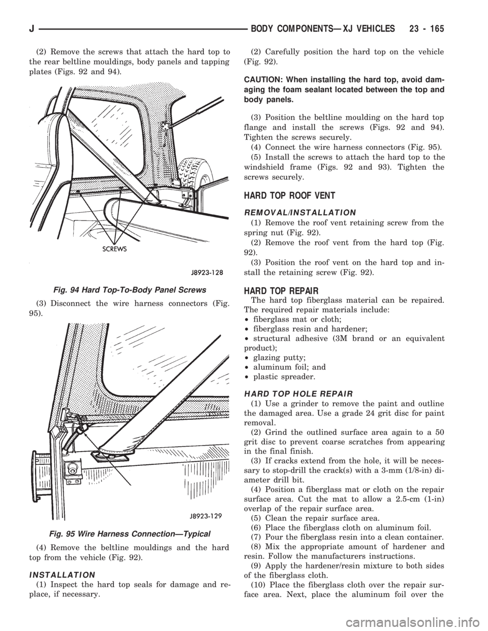
(2) Remove the screws that attach the hard top to
the rear beltline mouldings, body panels and tapping
plates (Figs. 92 and 94).
(3) Disconnect the wire harness connectors (Fig.
95).
(4) Remove the beltline mouldings and the hard
top from the vehicle (Fig. 92).
INSTALLATION
(1) Inspect the hard top seals for damage and re-
place, if necessary.(2) Carefully position the hard top on the vehicle
(Fig. 92).
CAUTION: When installing the hard top, avoid dam-
aging the foam sealant located between the top and
body panels.
(3) Position the beltline moulding on the hard top
flange and install the screws (Figs. 92 and 94).
Tighten the screws securely.
(4) Connect the wire harness connectors (Fig. 95).
(5) Install the screws to attach the hard top to the
windshield frame (Figs. 92 and 93). Tighten the
screws securely.
HARD TOP ROOF VENT
REMOVAL/INSTALLATION
(1) Remove the roof vent retaining screw from the
spring nut (Fig. 92).
(2) Remove the roof vent from the hard top (Fig.
92).
(3) Position the roof vent on the hard top and in-
stall the retaining screw (Fig. 92).
HARD TOP REPAIR
The hard top fiberglass material can be repaired.
The required repair materials include:
²fiberglass mat or cloth;
²fiberglass resin and hardener;
²structural adhesive (3M brand or an equivalent
product);
²glazing putty;
²aluminum foil; and
²plastic spreader.
HARD TOP HOLE REPAIR
(1) Use a grinder to remove the paint and outline
the damaged area. Use a grade 24 grit disc for paint
removal.
(2) Grind the outlined surface area again to a 50
grit disc to prevent coarse scratches from appearing
in the final finish.
(3) If cracks extend from the hole, it will be neces-
sary to stop-drill the crack(s) with a 3-mm (1/8-in) di-
ameter drill bit.
(4) Position a fiberglass mat or cloth on the repair
surface area. Cut the mat to allow a 2.5-cm (1-in)
overlap of the repair surface area.
(5) Clean the repair surface area.
(6) Place the fiberglass cloth on aluminum foil.
(7) Pour the fiberglass resin into a clean container.
(8) Mix the appropriate amount of hardener and
resin. Follow the manufacturers instructions.
(9) Apply the hardener/resin mixture to both sides
of the fiberglass cloth.
(10) Place the fiberglass cloth over the repair sur-
face area. Next, place the aluminum foil over the
Fig. 94 Hard Top-To-Body Panel Screws
Fig. 95 Wire Harness ConnectionÐTypical
JBODY COMPONENTSÐXJ VEHICLES 23 - 165
Page 1627 of 1784
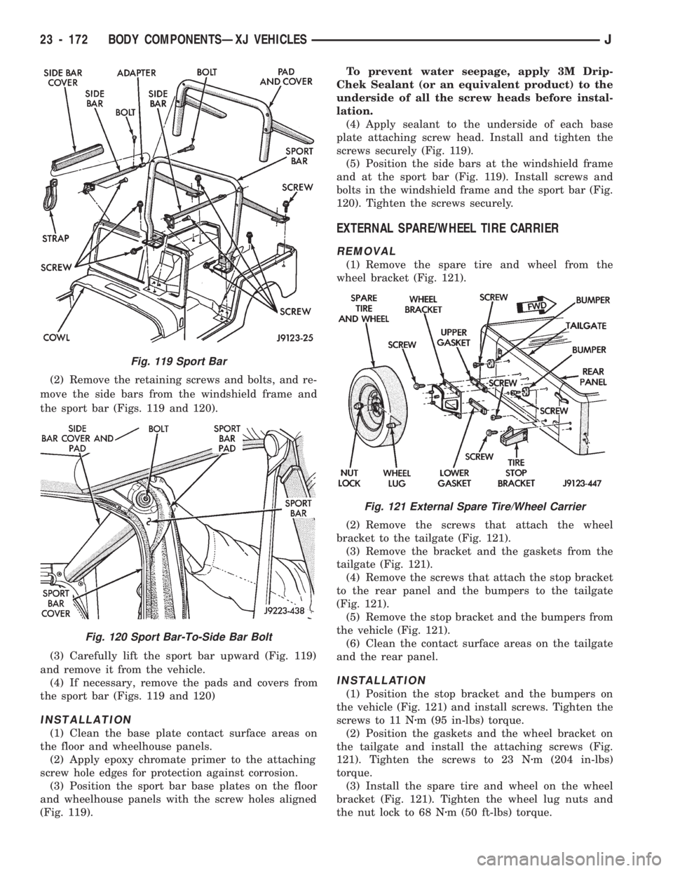
(2) Remove the retaining screws and bolts, and re-
move the side bars from the windshield frame and
the sport bar (Figs. 119 and 120).
(3) Carefully lift the sport bar upward (Fig. 119)
and remove it from the vehicle.
(4) If necessary, remove the pads and covers from
the sport bar (Figs. 119 and 120)
INSTALLATION
(1) Clean the base plate contact surface areas on
the floor and wheelhouse panels.
(2) Apply epoxy chromate primer to the attaching
screw hole edges for protection against corrosion.
(3) Position the sport bar base plates on the floor
and wheelhouse panels with the screw holes aligned
(Fig. 119).To prevent water seepage, apply 3M Drip-
Chek Sealant (or an equivalent product) to the
underside of all the screw heads before instal-
lation.
(4) Apply sealant to the underside of each base
plate attaching screw head. Install and tighten the
screws securely (Fig. 119).
(5) Position the side bars at the windshield frame
and at the sport bar (Fig. 119). Install screws and
bolts in the windshield frame and the sport bar (Fig.
120). Tighten the screws securely.
EXTERNAL SPARE/WHEEL TIRE CARRIER
REMOVAL
(1) Remove the spare tire and wheel from the
wheel bracket (Fig. 121).
(2) Remove the screws that attach the wheel
bracket to the tailgate (Fig. 121).
(3) Remove the bracket and the gaskets from the
tailgate (Fig. 121).
(4) Remove the screws that attach the stop bracket
to the rear panel and the bumpers to the tailgate
(Fig. 121).
(5) Remove the stop bracket and the bumpers from
the vehicle (Fig. 121).
(6) Clean the contact surface areas on the tailgate
and the rear panel.
INSTALLATION
(1) Position the stop bracket and the bumpers on
the vehicle (Fig. 121) and install screws. Tighten the
screws to 11 Nzm (95 in-lbs) torque.
(2) Position the gaskets and the wheel bracket on
the tailgate and install the attaching screws (Fig.
121). Tighten the screws to 23 Nzm (204 in-lbs)
torque.
(3) Install the spare tire and wheel on the wheel
bracket (Fig. 121). Tighten the wheel lug nuts and
the nut lock to 68 Nzm (50 ft-lbs) torque.
Fig. 119 Sport Bar
Fig. 120 Sport Bar-To-Side Bar Bolt
Fig. 121 External Spare Tire/Wheel Carrier
23 - 172 BODY COMPONENTSÐXJ VEHICLESJ
Page 1629 of 1784
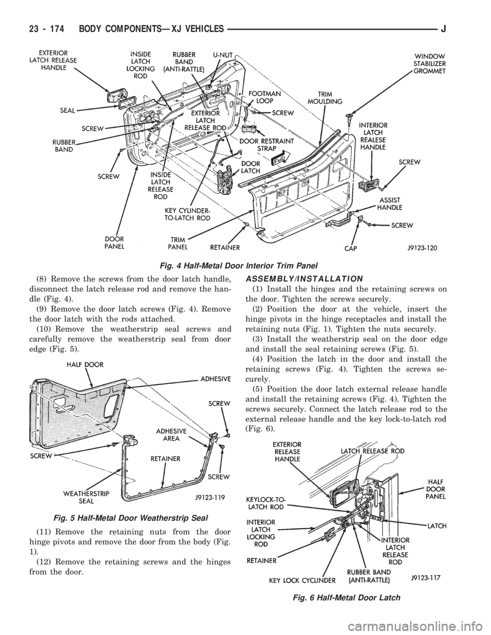
(8) Remove the screws from the door latch handle,
disconnect the latch release rod and remove the han-
dle (Fig. 4).
(9) Remove the door latch screws (Fig. 4). Remove
the door latch with the rods attached.
(10) Remove the weatherstrip seal screws and
carefully remove the weatherstrip seal from door
edge (Fig. 5).
(11) Remove the retaining nuts from the door
hinge pivots and remove the door from the body (Fig.
1).
(12) Remove the retaining screws and the hinges
from the door.ASSEMBLY/INSTALLATION
(1) Install the hinges and the retaining screws on
the door. Tighten the screws securely.
(2) Position the door at the vehicle, insert the
hinge pivots in the hinge receptacles and install the
retaining nuts (Fig. 1). Tighten the nuts securely.
(3) Install the weatherstrip seal on the door edge
and install the seal retaining screws (Fig. 5).
(4) Position the latch in the door and install the
retaining screws (Fig. 4). Tighten the screws se-
curely.
(5) Position the door latch external release handle
and install the retaining screws (Fig. 4). Tighten the
screws securely. Connect the latch release rod to the
external release handle and the key lock-to-latch rod
(Fig. 6).
Fig. 4 Half-Metal Door Interior Trim Panel
Fig. 5 Half-Metal Door Weatherstrip Seal
Fig. 6 Half-Metal Door Latch
23 - 174 BODY COMPONENTSÐXJ VEHICLESJ
Page 1633 of 1784
(6) Install the door waterdam and the trim panel
(Figs. 8 and 10).
FULL-METAL DOOR WINDOW GLASS
ADJUSTMENT
One adjustment location provides amount of effort
required to raise and lower the door window glass.
The door window glass division channel is adjustable
fore and aft at the lower attaching location.
(1) Remove the door trim panel and the waterdam
(Figs. 8 and 10).
(2) Loosen channel lower adjustment screw and
move the division channel fore or aft to obtain the
desired door window glass operation.
Movement of the division channel fore or aft
will decrease or increase the free-play between
the channels.
(3) Tighten the division channel lower adjustment
screw.
(4) Install the door waterdam and the trim panel
(Figs. 8 and 10).
REMOVAL
(1) Remove the door trim panel and the waterdam
(Figs. 8 and 10).
(2) Remove the window glass down-stop bumper
(Fig. 11).
(3) Remove the screws that attach the regulator
arm guide to the window glass. Remove the screws,
bushings, nuts and the guide from the glass (Fig. 11).
(4) Lower the window glass to the bottom of the
door.
(5) Remove the division channel upper attaching
screw and the lower adjustment screw. Detach the
front 3 inches of window glass weatherstrip seal from
the door upper frame.
(6) Separate the division channel from the front
window glass rubber seal. Pull the division channel
up and in toward the inside of vehicle.
(7) Raise and tilt the window glass toward the
hinge side of the door and disengage it from the rear
channel.
(8) Pull the window glass up and out of the door
panel.
INSTALLATION
(1) Lower the window glass into the door, while in-
serting the window glass into the front and rear
channels.
(2) Slide the window glass downward to the bottom
of the door panel.
(3) Lower the division channel into the door and
position the window glass securely in the channel.
(4) Install the weatherstrip seal in the upper door
frame and install the upper attaching screw and the
lower adjustment screw.(5) Slide the guide onto the regulator arm and po-
sition the guide on the window glass. Install the re-
taining nuts, bushings and screws (Fig. 12).
(6) Install the window glass down-stop bumper
(Fig. 11).
(7) Test the window operation for proper adjust-
ment.
(8) Install the door waterdam and the trim panel
(Fig. 8 and 10).
FULL-METAL DOOR KEY LOCK CYLINDER
REMOVAL
(1) Remove the door trim panel and the waterdam
(Figs. 8 and 10).
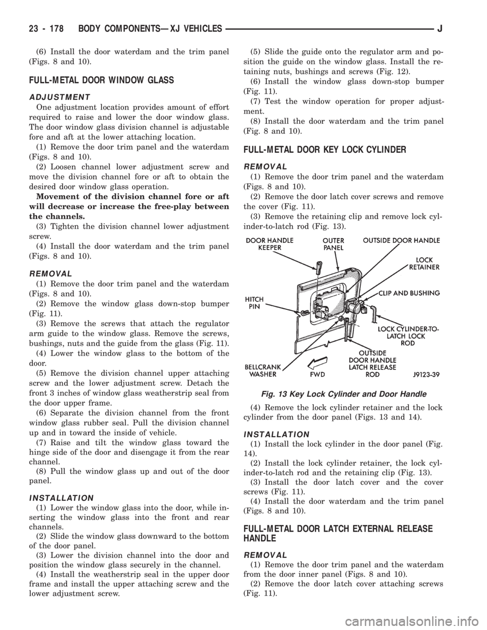
(2) Remove the door latch cover screws and remove
the cover (Fig. 11).
(3) Remove the retaining clip and remove lock cyl-
inder-to-latch rod (Fig. 13).
(4) Remove the lock cylinder retainer and the lock
cylinder from the door panel (Figs. 13 and 14).
INSTALLATION
(1) Install the lock cylinder in the door panel (Fig.
14).
(2) Install the lock cylinder retainer, the lock cyl-
inder-to-latch rod and the retaining clip (Fig. 13).
(3) Install the door latch cover and the cover
screws (Fig. 11).
(4) Install the door waterdam and the trim panel
(Figs. 8 and 10).
FULL-METAL DOOR LATCH EXTERNAL RELEASE
HANDLE
REMOVAL
(1) Remove the door trim panel and the waterdam
from the door inner panel (Figs. 8 and 10).
(2) Remove the door latch cover attaching screws
(Fig. 11).
Fig. 13 Key Lock Cylinder and Door Handle
23 - 178 BODY COMPONENTSÐXJ VEHICLESJ
Page 1637 of 1784
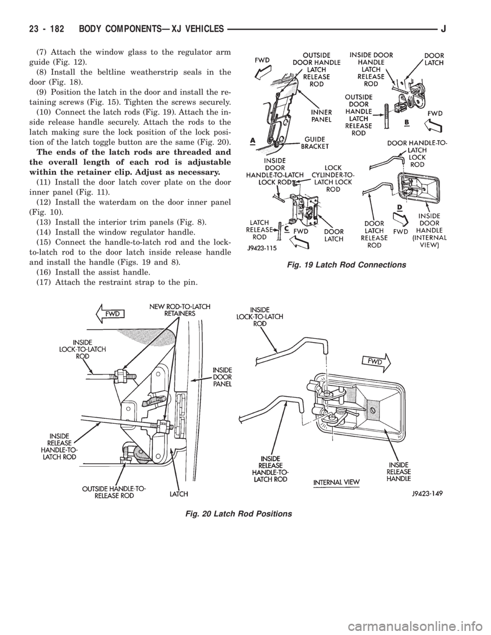
(7) Attach the window glass to the regulator arm
guide (Fig. 12).
(8) Install the beltline weatherstrip seals in the
door (Fig. 18).
(9) Position the latch in the door and install the re-
taining screws (Fig. 15). Tighten the screws securely.
(10) Connect the latch rods (Fig. 19). Attach the in-
side release handle securely. Attach the rods to the
latch making sure the lock position of the lock posi-
tion of the latch toggle button are the same (Fig. 20).
The ends of the latch rods are threaded and
the overall length of each rod is adjustable
within the retainer clip. Adjust as necessary.
(11) Install the door latch cover plate on the door
inner panel (Fig. 11).
(12) Install the waterdam on the door inner panel
(Fig. 10).
(13) Install the interior trim panels (Fig. 8).
(14) Install the window regulator handle.
(15) Connect the handle-to-latch rod and the lock-
to-latch rod to the door latch inside release handle
and install the handle (Figs. 19 and 8).
(16) Install the assist handle.
(17) Attach the restraint strap to the pin.
Fig. 20 Latch Rod Positions
Fig. 19 Latch Rod Connections
23 - 182 BODY COMPONENTSÐXJ VEHICLESJ
Page 1649 of 1784
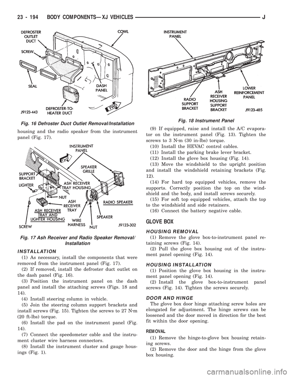
housing and the radio speaker from the instrument
panel (Fig. 17).
INSTALLATION
(1) As necessary, install the components that were
removed from the instrument panel (Fig. 17).
(2) If removed, install the defroster duct outlet on
the dash panel (Fig. 16).
(3) Position the instrument panel on the dash
panel and install the attaching screws (Figs. 18 and
14).
(4) Install steering column in vehicle.
(5) Join the steering column support brackets and
install screws (Fig. 15). Tighten the screws to 27 Nzm
(20 ft-lbs) torque.
(6) Install the pad on the instrument panel (Fig.
14).
(7) Connect the speedometer cable and the instru-
ment cluster wire harness connectors.
(8) Install the instrument cluster and gauge hous-
ings (Fig. 1).(9) If equipped, raise and install the A/C evapora-
tor on the instrument panel (Fig. 13). Tighten the
screws to 3 Nzm (30 in-lbs) torque.
(10) Install the HEVAC control cables.
(11) Install the parking brake lever bracket.
(12) Install the glove box housing (Fig. 14).
(13) Move the windshield to the upright position
and install the windshield retaining brackets (Fig.
12).
(14) For hard top equipped vehicles, remove the
supports. Correctly position the top on the wind-
shield and the body, and install screws securely.
(15) For soft top equipped vehicles, attach the top
to the windshield and side retainers.
(16) Connect the battery negative cable.
GLOVE BOX
HOUSING REMOVAL
(1) Remove the glove box-to-instrument panel re-
taining screws (Fig. 14).
(2) Pull the glove box housing out of the instru-
ment panel opening (Fig. 14).
HOUSING INSTALLATION
(1) Position the glove box housing in the instru-
ment panel opening (Fig. 14).
(2) Install the glove box-to-instrument panel
screws (Fig. 14). Tighten the screws securely.
DOOR AND HINGE
The glove box door hinge attaching screw holes are
elongated for adjustment. The hinge screws can be
loosened and the door moved in direction for the best
fit within the door opening.
REMOVAL
(1) Remove the hinge-to-glove box housing retain-
ing screws.
(2) Remove the door and the hinge from the glove
box housing.
Fig. 16 Defroster Duct Outlet Removal/Installation
Fig. 17 Ash Receiver and Radio Speaker Removal/
Installation
Fig. 18 Instrument Panel
23 - 194 BODY COMPONENTSÐXJ VEHICLESJ
Page 1650 of 1784
(3) If necessary, remove the retaining screws and
the hinge from the glove box door.
INSTALLATION
(1) If removed, install the hinge on the glove box
door with screws. Tighten the screws securely.
(2) Position the glove box door and hinge on the
glove box housing.
(3) Install the hinge-to-glove box housing screws
and adjust the door for proper fit within the opening.
Tighten the screws securely.
DOOR LATCH STRIKER ADJUSTMENT
The glove box door lock cylinder latch striker is at-
tached to the glove box housing opening with screws.
The striker can be moved in or out for adjustment.
SEATS
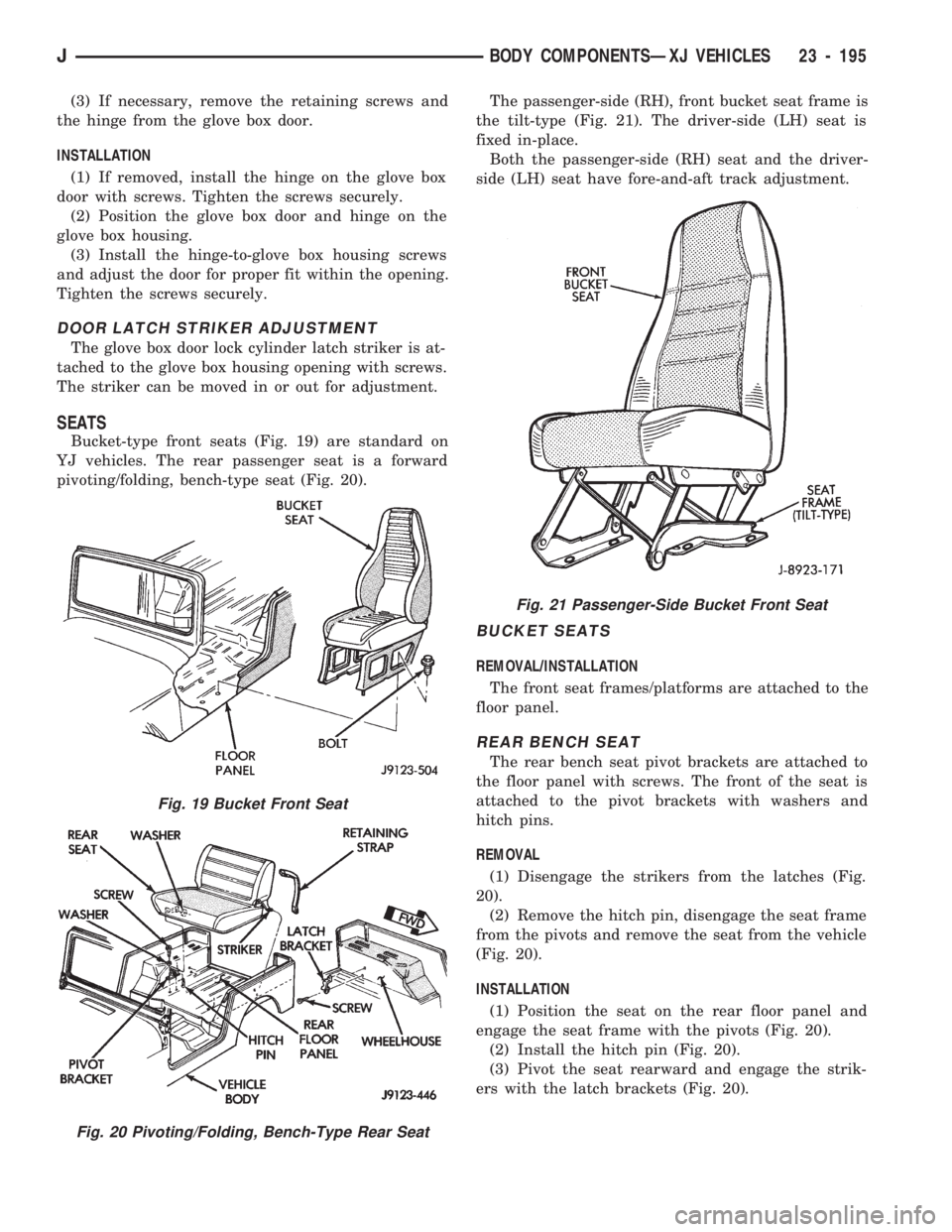
Bucket-type front seats (Fig. 19) are standard on
YJ vehicles. The rear passenger seat is a forward
pivoting/folding, bench-type seat (Fig. 20).The passenger-side (RH), front bucket seat frame is
the tilt-type (Fig. 21). The driver-side (LH) seat is
fixed in-place.
Both the passenger-side (RH) seat and the driver-
side (LH) seat have fore-and-aft track adjustment.
BUCKET SEATS
REMOVAL/INSTALLATION
The front seat frames/platforms are attached to the
floor panel.
REAR BENCH SEAT
The rear bench seat pivot brackets are attached to
the floor panel with screws. The front of the seat is
attached to the pivot brackets with washers and
hitch pins.
REMOVAL
(1) Disengage the strikers from the latches (Fig.
20).
(2) Remove the hitch pin, disengage the seat frame
from the pivots and remove the seat from the vehicle
(Fig. 20).
INSTALLATION
(1) Position the seat on the rear floor panel and
engage the seat frame with the pivots (Fig. 20).
(2) Install the hitch pin (Fig. 20).
(3) Pivot the seat rearward and engage the strik-
ers with the latch brackets (Fig. 20).
Fig. 19 Bucket Front Seat
Fig. 20 Pivoting/Folding, Bench-Type Rear Seat
Fig. 21 Passenger-Side Bucket Front Seat
JBODY COMPONENTSÐXJ VEHICLES 23 - 195
Page 1652 of 1784
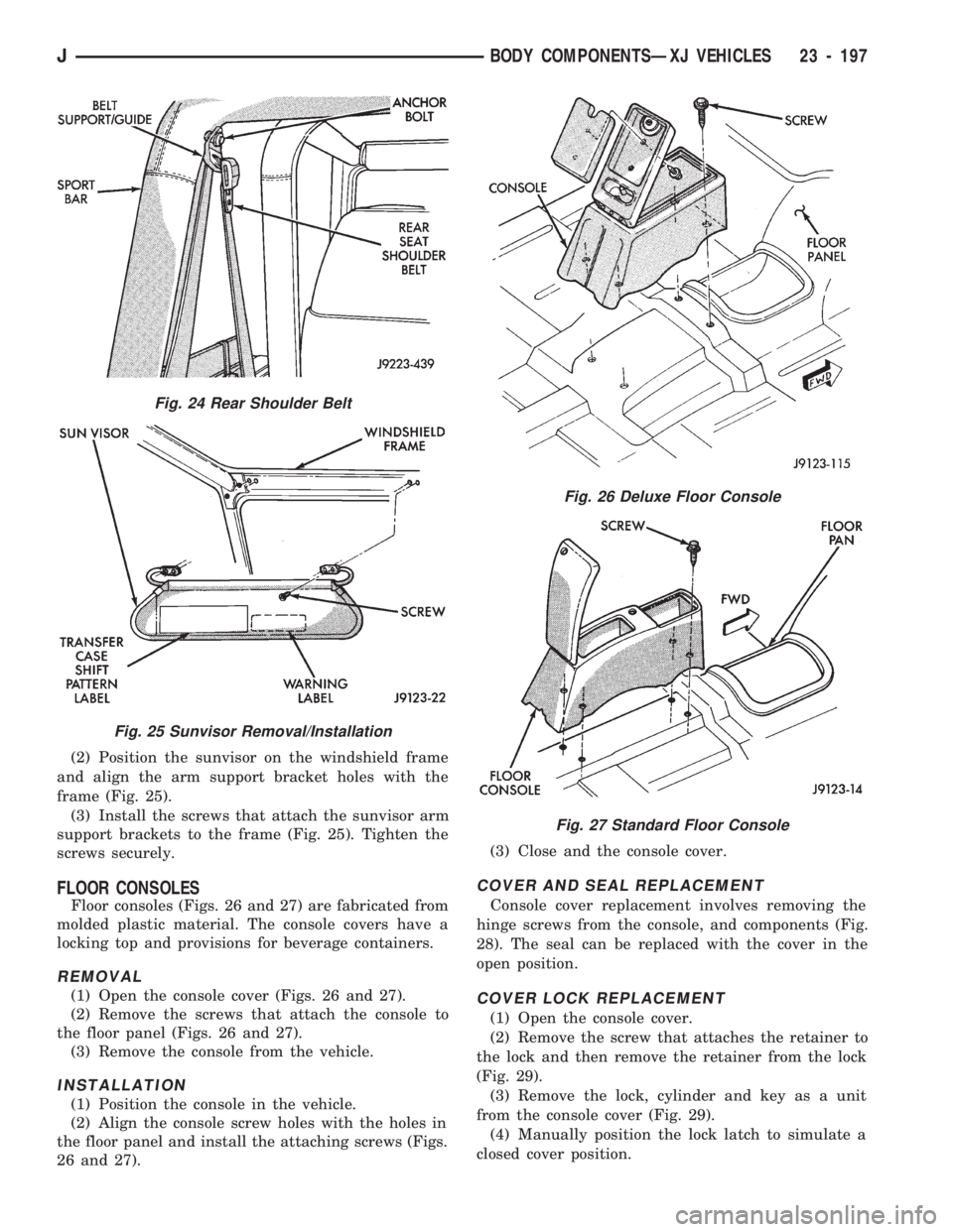
(2) Position the sunvisor on the windshield frame
and align the arm support bracket holes with the
frame (Fig. 25).
(3) Install the screws that attach the sunvisor arm
support brackets to the frame (Fig. 25). Tighten the
screws securely.
FLOOR CONSOLES
Floor consoles (Figs. 26 and 27) are fabricated from
molded plastic material. The console covers have a
locking top and provisions for beverage containers.
REMOVAL
(1) Open the console cover (Figs. 26 and 27).
(2) Remove the screws that attach the console to
the floor panel (Figs. 26 and 27).
(3) Remove the console from the vehicle.
INSTALLATION
(1) Position the console in the vehicle.
(2) Align the console screw holes with the holes in
the floor panel and install the attaching screws (Figs.
26 and 27).(3) Close and the console cover.
COVER AND SEAL REPLACEMENT
Console cover replacement involves removing the
hinge screws from the console, and components (Fig.
28). The seal can be replaced with the cover in the
open position.
COVER LOCK REPLACEMENT
(1) Open the console cover.
(2) Remove the screw that attaches the retainer to
the lock and then remove the retainer from the lock
(Fig. 29).
(3) Remove the lock, cylinder and key as a unit
from the console cover (Fig. 29).
(4) Manually position the lock latch to simulate a
closed cover position.
Fig. 24 Rear Shoulder Belt
Fig. 25 Sunvisor Removal/Installation
Fig. 26 Deluxe Floor Console
Fig. 27 Standard Floor Console
JBODY COMPONENTSÐXJ VEHICLES 23 - 197