1994 JEEP CHEROKEE ECU
[x] Cancel search: ECUPage 1241 of 1784
seal ring is teflon with chamfered ends. The rear
ring is metal with interlocking ends.
Check the input shaft for wear, or damage. Replace
the shaft if worn, scored or damaged in any way.
ASSEMBLING REAR CLUTCH
(1) Soak clutch discs in transmission fluid while
assembling other clutch parts.
(2) Install new seal rings on clutch retainer hub
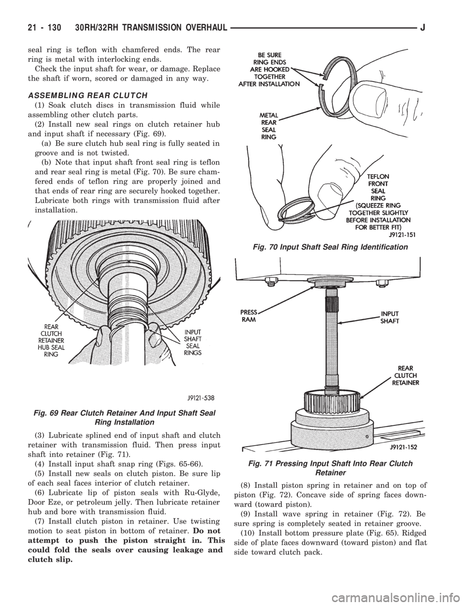
and input shaft if necessary (Fig. 69).
(a) Be sure clutch hub seal ring is fully seated in
groove and is not twisted.
(b) Note that input shaft front seal ring is teflon
and rear seal ring is metal (Fig. 70). Be sure cham-
fered ends of teflon ring are properly joined and
that ends of rear ring are securely hooked together.
Lubricate both rings with transmission fluid after
installation.
(3) Lubricate splined end of input shaft and clutch
retainer with transmission fluid. Then press input
shaft into retainer (Fig. 71).
(4) Install input shaft snap ring (Figs. 65-66).
(5) Install new seals on clutch piston. Be sure lip
of each seal faces interior of clutch retainer.
(6) Lubricate lip of piston seals with Ru-Glyde,
Door Eze, or petroleum jelly. Then lubricate retainer
hub and bore with transmission fluid.
(7) Install clutch piston in retainer. Use twisting
motion to seat piston in bottom of retainer.Do not
attempt to push the piston straight in. This
could fold the seals over causing leakage and
clutch slip.(8) Install piston spring in retainer and on top of
piston (Fig. 72). Concave side of spring faces down-
ward (toward piston).
(9) Install wave spring in retainer (Fig. 72). Be
sure spring is completely seated in retainer groove.
(10) Install bottom pressure plate (Fig. 65). Ridged
side of plate faces downward (toward piston) and flat
side toward clutch pack.
Fig. 69 Rear Clutch Retainer And Input Shaft Seal
Ring Installation
Fig. 70 Input Shaft Seal Ring Identification
Fig. 71 Pressing Input Shaft Into Rear Clutch
Retainer
21 - 130 30RH/32RH TRANSMISSION OVERHAULJ
Page 1249 of 1784
VALVE BODY DISASSEMBLY AND INSPECTION
CAUTION: Do not clamp any part of the valve body as-
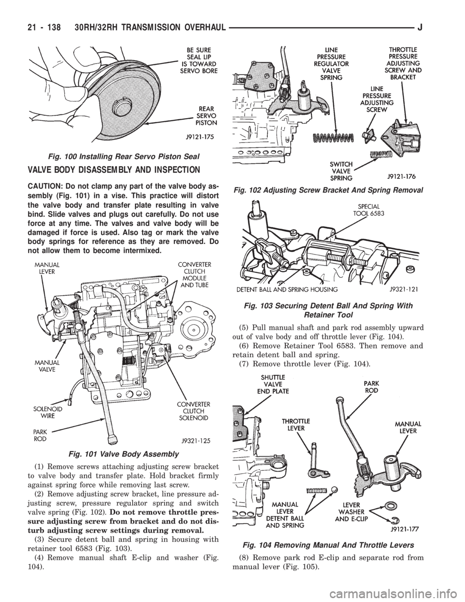
sembly (Fig. 101) in a vise. This practice will distort
the valve body and transfer plate resulting in valve
bind. Slide valves and plugs out carefully. Do not use
force at any time. The valves and valve body will be
damaged if force is used. Also tag or mark the valve
body springs for reference as they are removed. Do
not allow them to become intermixed.
(1) Remove screws attaching adjusting screw bracket
to valve body and transfer plate. Hold bracket firmly
against spring force while removing last screw.
(2) Remove adjusting screw bracket, line pressure ad-
justing screw, pressure regulator spring and switch
valve spring (Fig. 102).Do not remove throttle pres-
sure adjusting screw from bracket and do not dis-
turb adjusting screw settings during removal.
(3) Secure detent ball and spring in housing with
retainer tool 6583 (Fig. 103).
(4) Remove manual shaft E-clip and washer (Fig.
104).(5) Pull manual shaft and park rod assembly upward
out of valve body and off throttle lever (Fig. 104).
(6) Remove Retainer Tool 6583. Then remove and
retain detent ball and spring.
(7) Remove throttle lever (Fig. 104).
(8) Remove park rod E-clip and separate rod from
manual lever (Fig. 105).
Fig. 102 Adjusting Screw Bracket And Spring Removal
Fig. 103 Securing Detent Ball And Spring With
Retainer Tool
Fig. 104 Removing Manual And Throttle Levers
Fig. 100 Installing Rear Servo Piston Seal
Fig. 101 Valve Body Assembly
21 - 138 30RH/32RH TRANSMISSION OVERHAULJ
Page 1255 of 1784
VALVE BODY ASSEMBLY AND ADJUSTMENT
CAUTION: Do not force valves or plugs into place
during reassembly. If the valve body bores, valves
and plugs are free of distortion or burrs, the valve
body components should all slide into place easily.
In addition, do not overtighten the transfer plate
and valve body screws during reassembly. Over-
tightening can distort the valve body resulting in
valve sticking, cross leakage and unsatisfactory op-
eration. Tighten valve body screws to recom-
mended torque only.
(1) Lubricate valve body bores, valves and plugs
with ATF Plus, or Dexron IIŸ transmission fluid.
(2) Insert rear clutch and rear servo check balls in
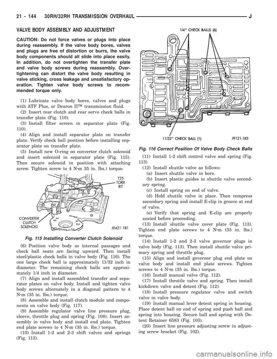
transfer plate (Fig. 110).
(3) Install filter screen in separator plate (Fig.
110).
(4) Align and install separator plate on transfer
plate. Verify check ball position before installing sep-
arator plate on transfer plate.
(5) Install new O-ring on converter clutch solenoid
and insert solenoid in separator plate (Fig. 115).
Then secure solenoid in position with attaching
screw. Tighten screw to 4 Nzm 35 in. lbs.) torque.
(6) Position valve body so internal passages and
check ball seats are facing upward. Then install
steel/plastic check balls in valve body (Fig. 116). The
one large check ball is approximately 11/32 inch in
diameter. The remaining check balls are approxi-
mately 1/4 inch in diameter.
(7) Align and install assembled transfer and sepa-
rator plates on valve body. Install and tighten valve
body screws alternately in a diagonal pattern to 4
Nzm (35 in. lbs.) torque.
(8) Assemble and install clutch module and compo-
nents on valve body (Fig. 117).
(9) Assemble regulator valve line pressure plug,
sleeve, throttle plug and spring (Fig. 108). Insert as-
sembly in valve body and install end plate. Tighten
end plate screws to 4 Nzm (35 in. lbs.) torque.
(10) Install 1-2 and 2-3 shift valves and springs
(Fig. 113).(11) Install 1-2 shift control valve and spring (Fig.
113)
(12) Install shuttle valve as follows:
(a) Insert shuttle valve in bore.
(b) Insert plastic guides in shuttle valve second-
ary spring.
(c) Install spring on end of valve.
(d) Hold shuttle valve in place. Then compress
secondary spring and install E-clip in groove at end
of valve.
(e) Verify that spring and E-clip are properly
seated before proceeding.
(13) Install shuttle valve cover plate (Fig. 113).
Tighten end plate screws to 4 Nzm (35 in. lbs.)
torque.
(14) Install 1-2 and 2-3 valve governor plugs in
valve body (Fig. 113). Then install shuttle valve pri-
mary spring and throttle plug.
(15) Align and install governor plug end plate on
valve body and install end plate screws. Tighten
screws to 4 Nzm (35 in. lbs.) torque.
(16) Install manual valve (Fig. 112).
(17) Install throttle valve and spring. Then install
kickdown valve and detent (Fig. 112).
(18) Install pressure regulator valve and switch
valve in valve body.
(19) Install manual lever detent spring in housing.
Place detent ball on end of spring and push ball and
spring into housing. Secure ball and spring with De-
tent Retainer 6583 (Fig. 103).
(20) Insert line pressure adjusting screw in adjust-
ing screw bracket (Fig. 102).
Fig. 116 Correct Position Of Valve Body Check Balls
Fig. 115 Installing Converter Clutch Solenoid
21 - 144 30RH/32RH TRANSMISSION OVERHAULJ
Page 1262 of 1784
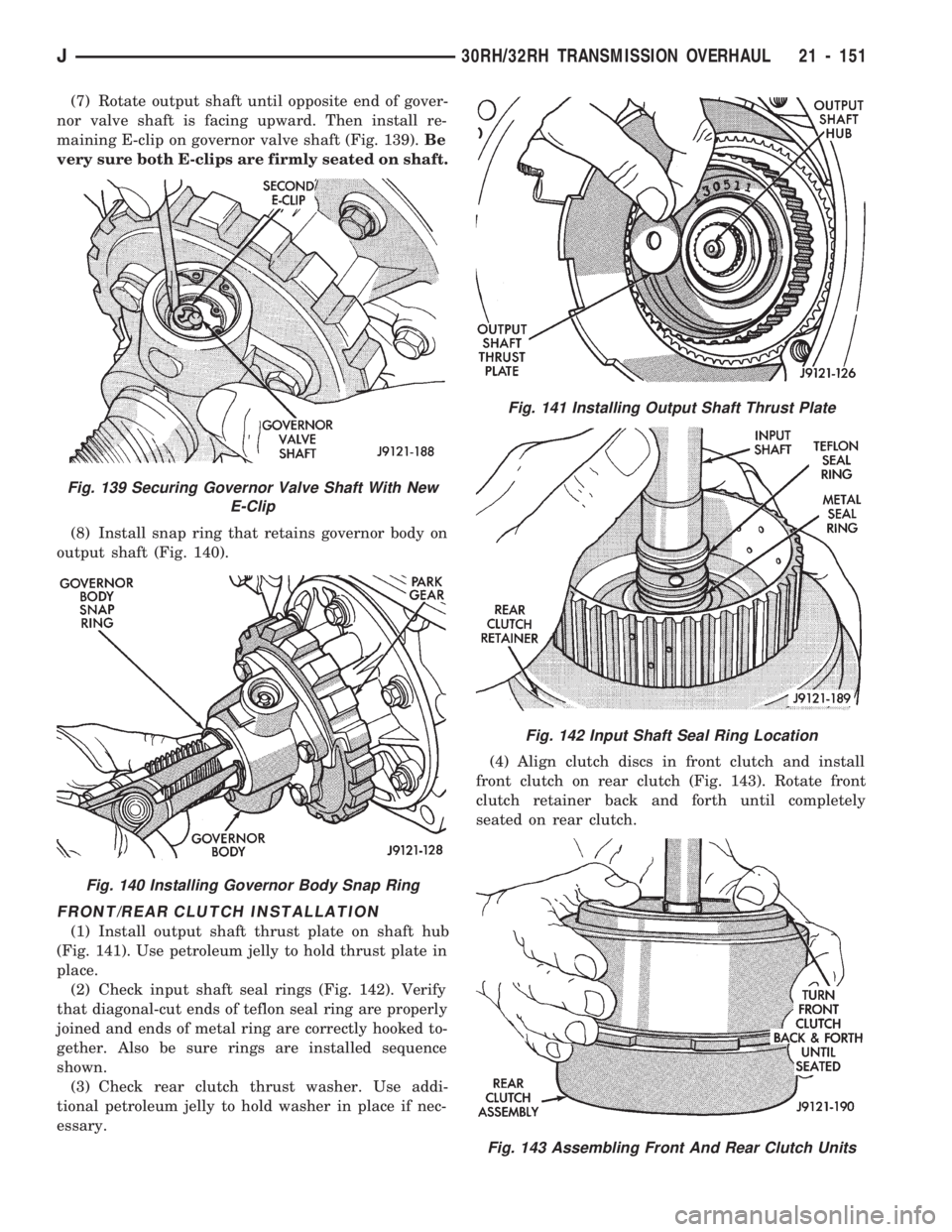
(7) Rotate output shaft until opposite end of gover-
nor valve shaft is facing upward. Then install re-
maining E-clip on governor valve shaft (Fig. 139).Be
very sure both E-clips are firmly seated on shaft.
(8) Install snap ring that retains governor body on
output shaft (Fig. 140).
FRONT/REAR CLUTCH INSTALLATION
(1) Install output shaft thrust plate on shaft hub
(Fig. 141). Use petroleum jelly to hold thrust plate in
place.
(2) Check input shaft seal rings (Fig. 142). Verify
that diagonal-cut ends of teflon seal ring are properly
joined and ends of metal ring are correctly hooked to-
gether. Also be sure rings are installed sequence
shown.
(3) Check rear clutch thrust washer. Use addi-
tional petroleum jelly to hold washer in place if nec-
essary.(4) Align clutch discs in front clutch and install
front clutch on rear clutch (Fig. 143). Rotate front
clutch retainer back and forth until completely
seated on rear clutch.
Fig. 139 Securing Governor Valve Shaft With New
E-Clip
Fig. 140 Installing Governor Body Snap Ring
Fig. 141 Installing Output Shaft Thrust Plate
Fig. 142 Input Shaft Seal Ring Location
Fig. 143 Assembling Front And Rear Clutch Units
J30RH/32RH TRANSMISSION OVERHAUL 21 - 151
Page 1266 of 1784
(c) Back off front band adjusting screw as fol-
lows:
²On 30RH (2.5L), back adjusting screw off 2
1/2 turns
²On 32RH (4.0L), back adjusting screw off 2
1/4 turns
(d) Hold adjusting screw in position and tighten
locknut to 34 Nzm (25 ft. lbs.).
(2) Adjustrear bandas follows:
(a) Loosen locknut.
(b) Tighten adjusting screw as follows: On 32RH
transmission, tighten screw to 8 Nzm (72 in. lbs).
torque. On 30RH transmission. Tighten screw to 5
Nzm (41 in. lbs.) torque.
(c) Back off rear band adjusting screw as follows:
²On 30RH (2.5L), back adjusting screw off 7
turns
²On 32RH (4.0L), back adjusting screw off 4
turns
(d) Hold adjusting screw in place and tighten
locknut to 34 Nzm (25 ft. lbs.) torque.(3) Install new pan gasket on transmission and in-
stall oil pan. Tighten pan bolts to 17 Nzm (13 ft. lbs.).
(4) Turn transmission over.
EXTENSION HOUSING, CONTROL LEVER AND
CONVERTER INSTALLATION
(1) Install throttle valve and manual valve levers
on shaft.
(2) Position new extension adapter housing gasket
on transmission case. Use petroleum jelly to hold
gasket in place.
(3) Install new rear seal in extension housing if re-
quired.
(4) Install extension/adapter housing on transmis-
sion case. Tighten housing fasteners to 33 Nzm (24 ft.
lbs.). Be sure park lock rod is properly engaged in
sprag before tightening fasteners.
(5) Lubricate converter hub with transmission
fluid and carefully install converter. Turn converter
back and forth until seated. Be sure converter hub
slots are fully seated in oil pump gear lugs.
(6) Secure converter in oil pump before mounting
transmission on jack and before moving transmission
back under vehicle. Use metal strapping, C-clamp, or
locking pliers to hold converter in place. Attach hold-
ing tool to converter housing.
CAUTION: The transmission cooler and lines must
be reverse flushed if overhaul corrected a malfunc-
tion that generated sludge, metal particles, or
clutch friction material. The torque converter should
also be replaced if contaminated by the same mal-
function. Debris and residue not flushed from the
cooler and lines will flow back into the transmission
and converter. The result could be a repeat failure
and shop comeback.
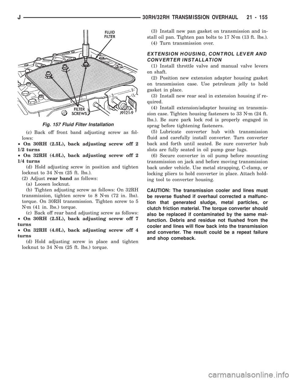
Fig. 157 Fluid Filter Installation
J30RH/32RH TRANSMISSION OVERHAUL 21 - 155
Page 1284 of 1784
AW-4 IN-VEHICLE SERVICE
INDEX
page page
Accumulator Pistons and Springs........... 179
Adapter Housing Seal Replacement.......... 182
Checking Fluid Level and Condition.......... 173
Manual Valve Shaft Seal Replacement....... 178
Park Interlock Cable Adjustment............ 186
Park Rod and Pawl Service................ 181
Park/Neutral Position Switch............... 173
Second Coast Brake Servo................ 181
Shift Cable Adjustment................... 186
Speed Sensor.......................... 182Speed Sensor RotorÐSpeedometer Drive Gear . 183
Throttle Position Sensor (TPS) Service....... 184
Transmission Control Module (TCM) Service . . . 173
Transmission Cooler Line Fittings........... 187
Transmission Cooler Service............... 187
Transmission Throttle Cable Adjustment....... 185
Transmission Throttle Cable Replacement..... 184
Transmission Valve Body Installation......... 177
Transmission Valve Body Removal.......... 176
Transmission Valve Body Solenoids.......... 175
CHECKING FLUID LEVEL AND CONDITION
Recommended fluid for AW-4 transmissions is Mo-
par Dexron IIE/Mercon. Mopar Dexron II may be
used if Mercon fluid is not readily available.
CHECKING FLUID LEVEL
(1) Be sure transmission fluid is at normal operat-
ing temperature. Normal operating temperature is
reached after approximately 15 miles (25 km) of op-
eration.
(2) Position vehicle on level surface. This is impor-
tant for an accurate fluid level check.
(3) Shift transmission through all gear ranges and
back to Park.
(4) Apply parking brakes.
(5) Verify that transmission is in Park.
(6) Wipe off dipstick handle to prevent dirt from
entering fill tube. Then remove dipstick and check
fluid level and condition.
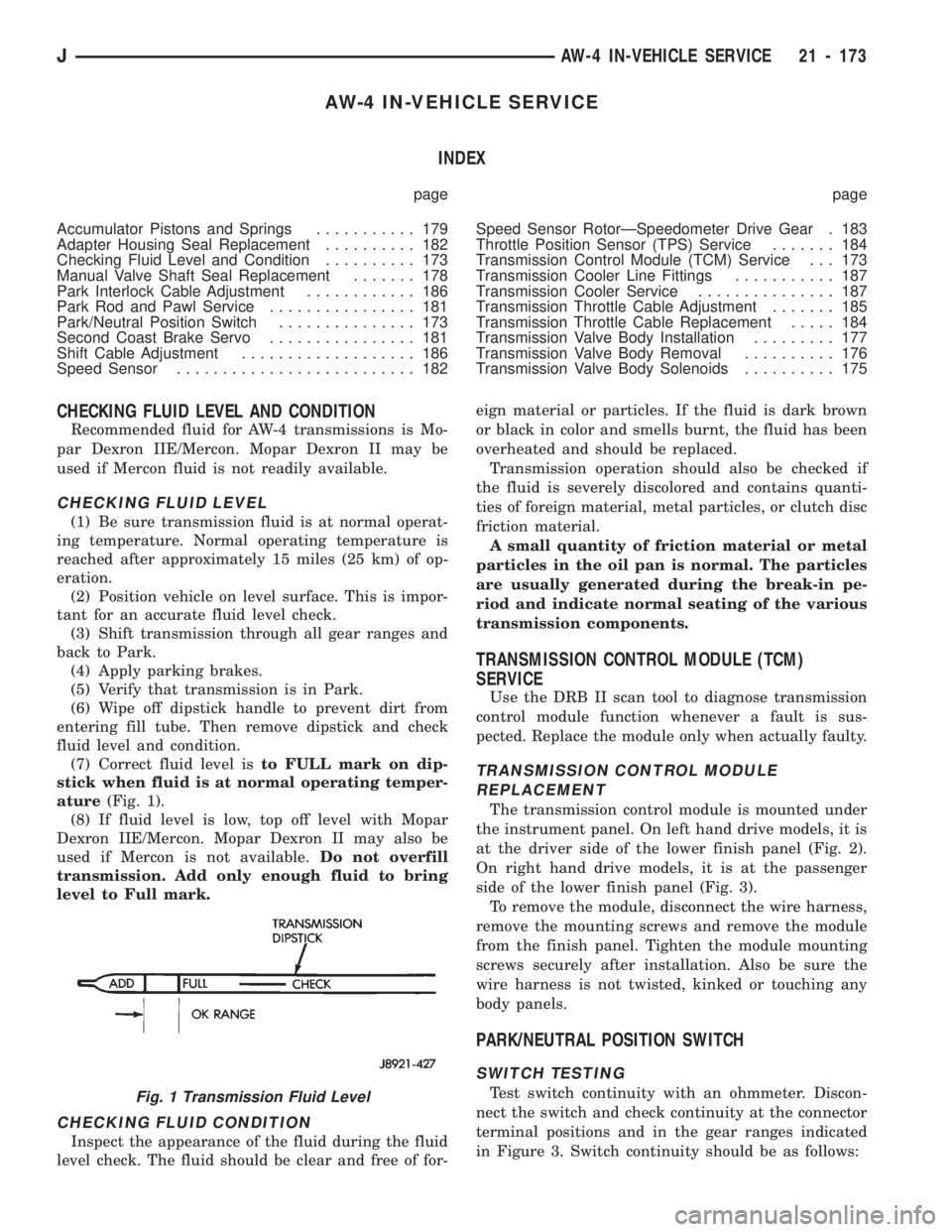
(7) Correct fluid level isto FULL mark on dip-
stick when fluid is at normal operating temper-
ature(Fig. 1).
(8) If fluid level is low, top off level with Mopar
Dexron IIE/Mercon. Mopar Dexron II may also be
used if Mercon is not available.Do not overfill
transmission. Add only enough fluid to bring
level to Full mark.
CHECKING FLUID CONDITION
Inspect the appearance of the fluid during the fluid
level check. The fluid should be clear and free of for-eign material or particles. If the fluid is dark brown
or black in color and smells burnt, the fluid has been
overheated and should be replaced.
Transmission operation should also be checked if
the fluid is severely discolored and contains quanti-
ties of foreign material, metal particles, or clutch disc
friction material.
A small quantity of friction material or metal
particles in the oil pan is normal. The particles
are usually generated during the break-in pe-
riod and indicate normal seating of the various
transmission components.
TRANSMISSION CONTROL MODULE (TCM)
SERVICE
Use the DRB II scan tool to diagnose transmission
control module function whenever a fault is sus-
pected. Replace the module only when actually faulty.
TRANSMISSION CONTROL MODULE
REPLACEMENT
The transmission control module is mounted under
the instrument panel. On left hand drive models, it is
at the driver side of the lower finish panel (Fig. 2).
On right hand drive models, it is at the passenger
side of the lower finish panel (Fig. 3).
To remove the module, disconnect the wire harness,
remove the mounting screws and remove the module
from the finish panel. Tighten the module mounting
screws securely after installation. Also be sure the
wire harness is not twisted, kinked or touching any
body panels.
PARK/NEUTRAL POSITION SWITCH
SWITCH TESTING
Test switch continuity with an ohmmeter. Discon-
nect the switch and check continuity at the connector
terminal positions and in the gear ranges indicated
in Figure 3. Switch continuity should be as follows:Fig. 1 Transmission Fluid Level
JAW-4 IN-VEHICLE SERVICE 21 - 173
Page 1286 of 1784
(8) Tighten switch adjusting bolt to 13 Nzm(9ft.
lbs.) torque.
(9) Bend at least two washer lock tabs over switch
attaching nut to secure it.
(10) Connect shift linkage rod to shift lever on left
side of case.
(11) Connect switch wires to harness and lower ve-
hicle.
(12) Check switch operation. Engine should start
in Park and Neutral only.
TRANSMISSION VALVE BODY SOLENOIDS
SOLENOID REMOVAL
(1) Remove transmission oil pan drain plug and
drain fluid.
(2) Remove pan bolts and remove oil pan.
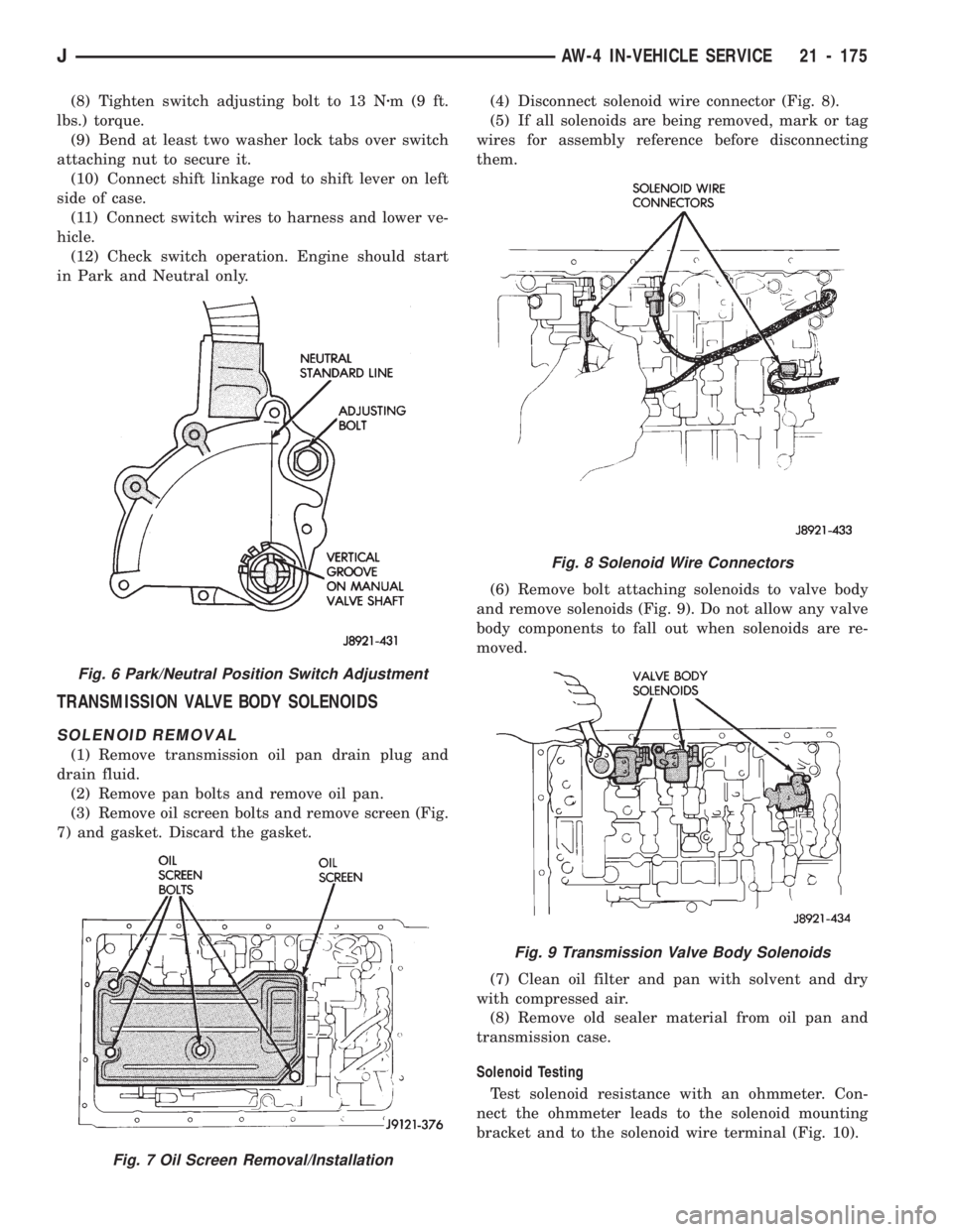
(3) Remove oil screen bolts and remove screen (Fig.
7) and gasket. Discard the gasket.(4) Disconnect solenoid wire connector (Fig. 8).
(5) If all solenoids are being removed, mark or tag
wires for assembly reference before disconnecting
them.
(6) Remove bolt attaching solenoids to valve body
and remove solenoids (Fig. 9). Do not allow any valve
body components to fall out when solenoids are re-
moved.
(7) Clean oil filter and pan with solvent and dry
with compressed air.
(8) Remove old sealer material from oil pan and
transmission case.
Solenoid Testing
Test solenoid resistance with an ohmmeter. Con-
nect the ohmmeter leads to the solenoid mounting
bracket and to the solenoid wire terminal (Fig. 10).
Fig. 8 Solenoid Wire Connectors
Fig. 9 Transmission Valve Body Solenoids
Fig. 6 Park/Neutral Position Switch Adjustment
Fig. 7 Oil Screen Removal/Installation
JAW-4 IN-VEHICLE SERVICE 21 - 175
Page 1287 of 1784
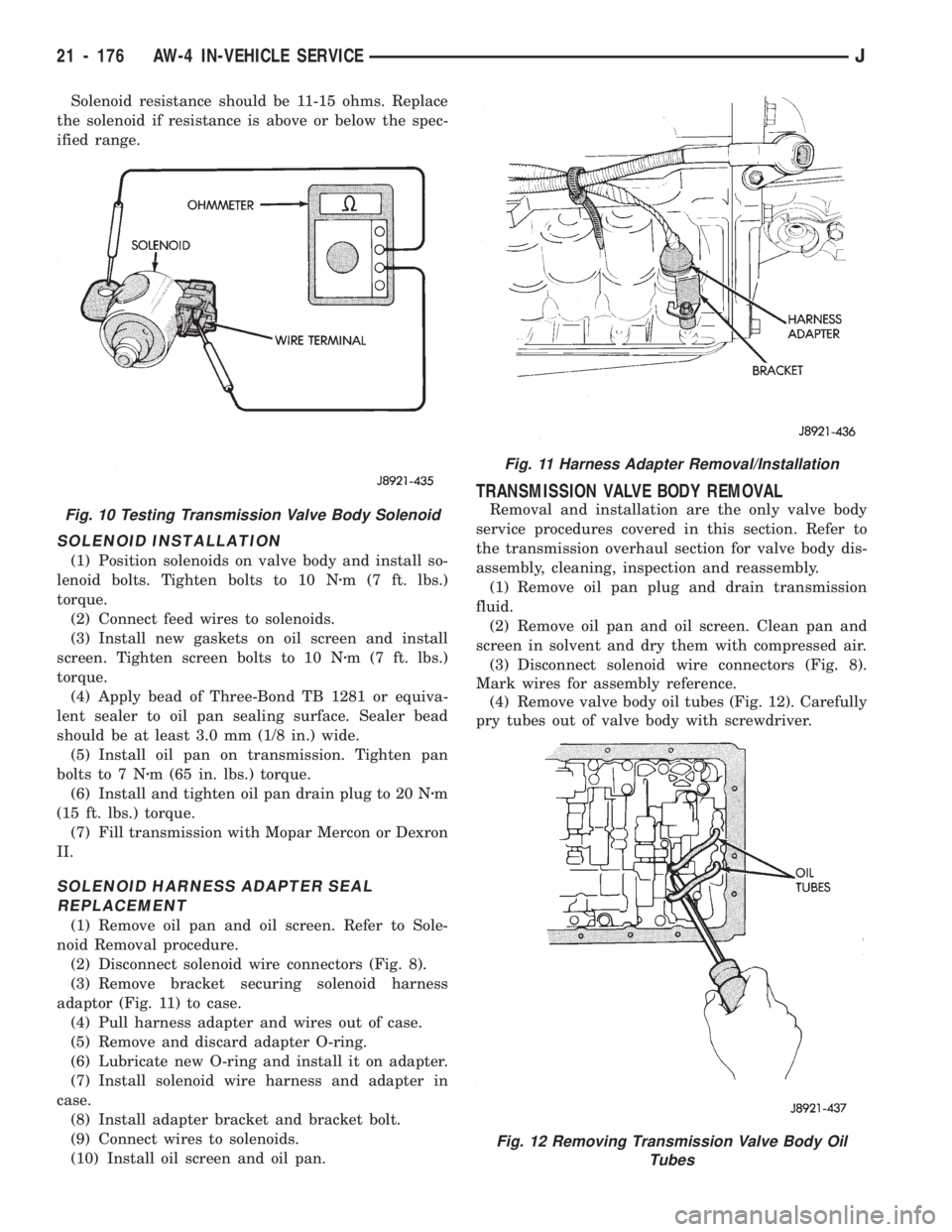
Solenoid resistance should be 11-15 ohms. Replace
the solenoid if resistance is above or below the spec-
ified range.
SOLENOID INSTALLATION
(1) Position solenoids on valve body and install so-
lenoid bolts. Tighten bolts to 10 Nzm (7 ft. lbs.)
torque.
(2) Connect feed wires to solenoids.
(3) Install new gaskets on oil screen and install
screen. Tighten screen bolts to 10 Nzm (7 ft. lbs.)
torque.
(4) Apply bead of Three-Bond TB 1281 or equiva-
lent sealer to oil pan sealing surface. Sealer bead
should be at least 3.0 mm (1/8 in.) wide.
(5) Install oil pan on transmission. Tighten pan
bolts to 7 Nzm (65 in. lbs.) torque.
(6) Install and tighten oil pan drain plug to 20 Nzm
(15 ft. lbs.) torque.
(7) Fill transmission with Mopar Mercon or Dexron
II.
SOLENOID HARNESS ADAPTER SEAL
REPLACEMENT
(1) Remove oil pan and oil screen. Refer to Sole-
noid Removal procedure.
(2) Disconnect solenoid wire connectors (Fig. 8).
(3) Remove bracket securing solenoid harness
adaptor (Fig. 11) to case.
(4) Pull harness adapter and wires out of case.
(5) Remove and discard adapter O-ring.
(6) Lubricate new O-ring and install it on adapter.
(7) Install solenoid wire harness and adapter in
case.
(8) Install adapter bracket and bracket bolt.
(9) Connect wires to solenoids.
(10) Install oil screen and oil pan.
TRANSMISSION VALVE BODY REMOVAL
Removal and installation are the only valve body
service procedures covered in this section. Refer to
the transmission overhaul section for valve body dis-
assembly, cleaning, inspection and reassembly.
(1) Remove oil pan plug and drain transmission
fluid.
(2) Remove oil pan and oil screen. Clean pan and
screen in solvent and dry them with compressed air.
(3) Disconnect solenoid wire connectors (Fig. 8).
Mark wires for assembly reference.
(4) Remove valve body oil tubes (Fig. 12). Carefully
pry tubes out of valve body with screwdriver.
Fig. 11 Harness Adapter Removal/Installation
Fig. 12 Removing Transmission Valve Body Oil
Tubes
Fig. 10 Testing Transmission Valve Body Solenoid
21 - 176 AW-4 IN-VEHICLE SERVICEJ