1994 JEEP CHEROKEE ECU
[x] Cancel search: ECUPage 897 of 1784
(29) Disconnect the engine speed sensor wire con-
nection.
(30) Remove the exhaust pipe support.
(31) Remove the flywheel/converter housing access
cover.
(32)Vehicles with Automatic Transmission:
(a) Mark the converter and drive plate location.
(b) Remove the converter-to-drive plate bolts.
(33) Remove the upper flywheel/converter housing
bolts and loosen the bottom bolts.
(34) Remove the engine mount cushion-to-engine
compartment bracket bolts.
(35) Lower the vehicle.
(36) Attach a lifting device to the engine.
(37) Raise the engine off the front supports.
(38) Place a support or floor jack under the con-
verter (or flywheel) housing.
(39) Remove the remaining converter (or flywheel)
housing bolts.
(40) Lift the engine out of the engine compart-
ment.
INSTALLATION
CAUTION: When installing the engine into a vehicle
equipped with an automatic transmission, be care-
ful not to damage the trigger wheel on the flywheel.
(1) Attach a lifting device to the engine and lower
the engine into the engine compartment. For easier
installation, it may be necessary to remove the en-
gine mount cushions from the engine mount bracket
as an aide in alignment of the engine to the trans-
mission.
(2)Vehicles with Manual Transmission:
(a) Insert the transmission shaft into the clutch
spline.
(b) Align the flywheel housing with the engine.
(c) Install and tighten the flywheel housing
lower bolts finger tight.(3)Vehicles with Automatic Transmission:
(a) Align the transmission torque converter
housing with the engine.
(b) Loosely install the converter housing lower
bolts and install the next higher bolt and nut on
each side.
(c) Tighten all 4 bolts finger tight.
(4) Install the engine mount cushions (if removed).
(5) Lower the engine and engine mount cushions
onto the engine compartment brackets. Install the
bolts and finger tighten the nuts.
(6) Remove the engine lifting device.
(7) Raise and support the vehicle.
(8) Install the remaining flywheel/converter hous-
ing bolts. Tighten all bolts to 38 Nzm (28 ft. lbs.)
torque.
(9)Vehicles with Automatic Transmission:
(a) Install the converter-to-drive plate bolts.
(b) Ensure the installation reference marks are
aligned.
(10) Install the flywheel/converter housing access
cover.
(11) Install the exhaust pipe support and tighten
the screw.
(12) Tighten the engine mount-to-bracket bolts.
(13) Connect the engine speed sensor wire connec-
tions and tighten the screws.
(14) Connect the exhaust pipe to the manifold.
(15) Install the starter motor and connect the ca-
ble.
(16) Connect the wires to the starter motor sole-
noid.
(17) Lower the vehicle.
(18) Connect all the vacuum hoses and wire con-
nectors identified during engine removal.
(19) If equipped with power steering:
(a) Remove the protective caps
(b) Connect the hoses to the fittings at the steer-
ing gear. Tighten the nut to 52 Nzm (38 ft. lbs.)
torque.
(c) Fill the pump reservoir with fluid.
(20) Install the power brake vacuum check valve
to the booster, if equipped.
(21) Connect the fuel inlet and return hoses at the
fuel rail. Verify that the quick-connect fitting assem-
bly fits securely over the fuel lines by giving the fuel
lines a firm tug.
(22) Install the fuel line bracket to the intake
manifold.
(23) Connect the distributor electrical connector
and oil pressure switch connector.
(24) Connect the injection system wire harness
connector on the dash panel.
(25) Connect the line pressure cable (if equipped
with automatic transmission).
(26) Connect the speed control cable, if equipped.
(27) Connect the throttle cable linkages.
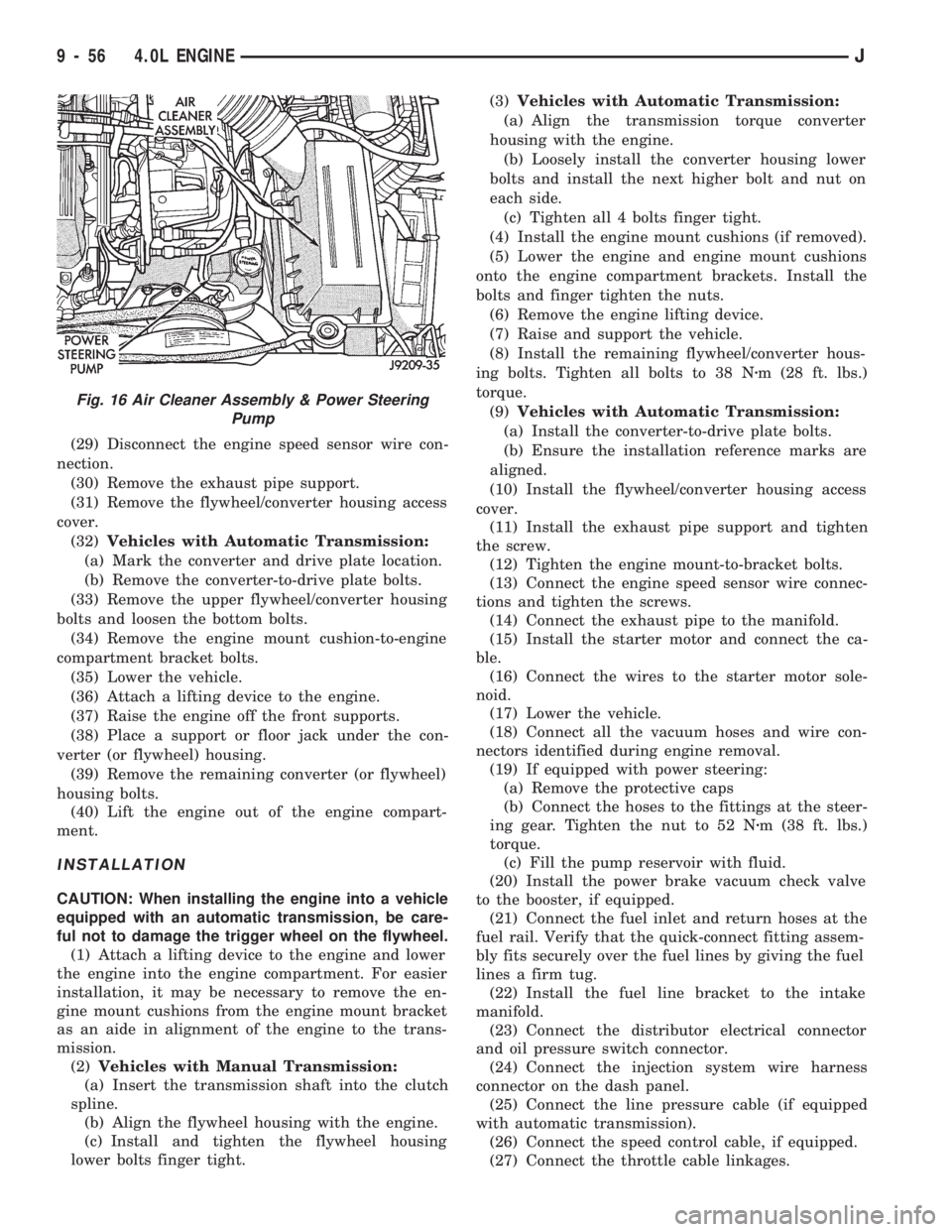
Fig. 16 Air Cleaner Assembly & Power Steering
Pump
9 - 56 4.0L ENGINEJ
Page 900 of 1784
(17) Tighten the serpentine drive belt according to
the specifications listed in Group 7, Cooling System.
(18) Install the fan shroud and radiator (refer to
Group 7, Cooling System for the proper procedure).
(19) Connect the radiator hoses.
(20) Connect the throttle valve rod and retainer.
(21) Connect the throttle cable and install the rod.
(22) Install the throttle valve rod spring.
(23) Connect the speed control cable, if equipped.
(24) Connect the oxygen sensor wire connector.
(25) Install the vacuum hose and check valve on
the brake booster.
(26) Connect the coolant temperature sensor wire
connector.
(27) Connect the idle speed actuator wire connec-
tor.
(28) Connect the fuel inlet and return hoses at the
fuel rail. Verify that the quick-connect fitting assem-
bly fits securely over the fuel lines by giving the fuel
lines a firm tug.
(29) Install the fuel line bracket to the intake
manifold.
(30) Connect all fuel injection wire connections.
(31) Install the engine ground strap.
(32) Connect the ignition coil wire connector.
(33) Remove the coolant temperature sending unit
to permit air to escape from the block. Fill the cool-
ing system with coolant. Install the coolant tempera-
ture sending unit when the system is filled.
(34) If equipped with power steering:
(a) Remove the protective caps
(b) Connect the hoses to the fittings at the steer-
ing gear. Tighten the nut to 52 Nzm (38 ft. lbs.)
torque.
(c) Fill the pump reservoir with fluid.
(35) Install the battery and connect the battery ca-
bles.
(36) Install the air cleaner bonnet to the throttle
body.
(37) Install the air cleaner.
(38) Lower the hood and secure in place.
(39) Start the engine and inspect for leaks.
(40) Stop the engine and check the fluid levels.
Add fluid, as required.
ENGINE CYLINDER HEAD COVER
A cured gasket is part of the engine cylinder head
cover.
REMOVAL
(1) Disconnect negative cable from battery.
(2) Disconnect the Crankcase Ventilation (CCV)
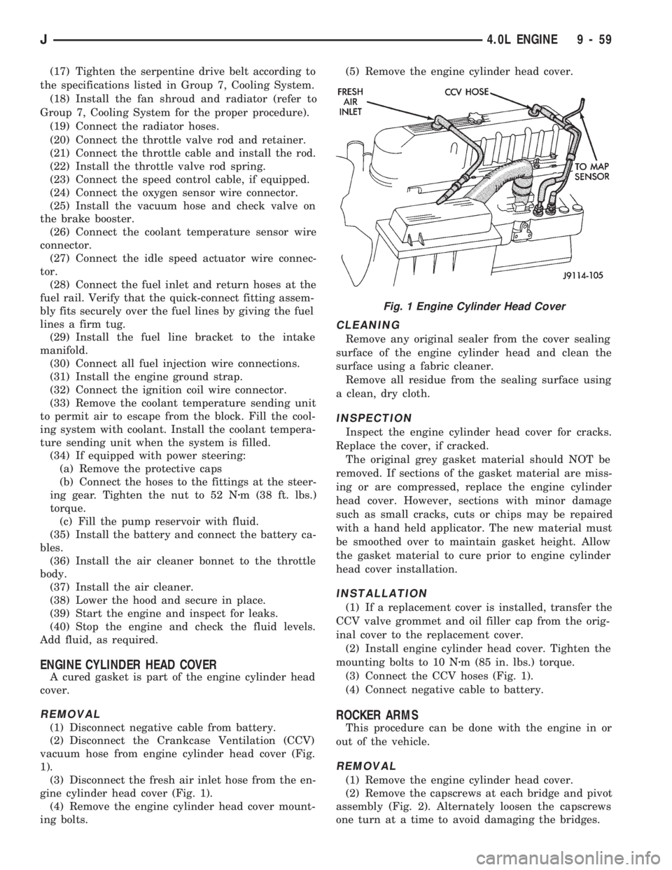
vacuum hose from engine cylinder head cover (Fig.
1).
(3) Disconnect the fresh air inlet hose from the en-
gine cylinder head cover (Fig. 1).
(4) Remove the engine cylinder head cover mount-
ing bolts.(5) Remove the engine cylinder head cover.
CLEANING
Remove any original sealer from the cover sealing
surface of the engine cylinder head and clean the
surface using a fabric cleaner.
Remove all residue from the sealing surface using
a clean, dry cloth.
INSPECTION
Inspect the engine cylinder head cover for cracks.
Replace the cover, if cracked.
The original grey gasket material should NOT be
removed. If sections of the gasket material are miss-
ing or are compressed, replace the engine cylinder
head cover. However, sections with minor damage
such as small cracks, cuts or chips may be repaired
with a hand held applicator. The new material must
be smoothed over to maintain gasket height. Allow
the gasket material to cure prior to engine cylinder
head cover installation.
INSTALLATION
(1) If a replacement cover is installed, transfer the
CCV valve grommet and oil filler cap from the orig-
inal cover to the replacement cover.
(2) Install engine cylinder head cover. Tighten the
mounting bolts to 10 Nzm (85 in. lbs.) torque.
(3) Connect the CCV hoses (Fig. 1).
(4) Connect negative cable to battery.
ROCKER ARMS
This procedure can be done with the engine in or
out of the vehicle.
REMOVAL
(1) Remove the engine cylinder head cover.
(2) Remove the capscrews at each bridge and pivot
assembly (Fig. 2). Alternately loosen the capscrews
one turn at a time to avoid damaging the bridges.
Fig. 1 Engine Cylinder Head Cover
J4.0L ENGINE 9 - 59
Page 939 of 1784
INTAKE MANIFOLDÐ2.5L ENGINE
REMOVAL
(1) Disconnect the battery negative cable.
(2) Remove the air inlet hose from the throttle
body and air cleaner.
(3) Loosen the accessory drive belt tension and re-
move the belt from the power steering pump.
(4) Remove the power steering pump and brackets
from the water pump and intake manifold. Support
power steering pump and bracket with mechanics
wire attached to the radiator upper crossmember.
(5) Remove the fuel tank filler cap to relieve the
fuel tank pressure.
(6) Install the fuel tank filler cap.
(7) Disconnect fuel supply and return tube from
the fuel rail (refer to Group 14, Fuel System - Quick
Connect Fittings).
(8) Disconnect the accelerator cable from the throt-
tle body and the holddown bracket.
CAUTION: When disconnecting the cruise control
connector at the throttle body, DO NOT pry the con-
nector off with pliers or screwdriver. Use finger
pressure only. Prying the connector off could break
it.
(9) Disconnect the electrical connectors. Pull the
harnesses away from the manifold.
²The throttle position sensor.
²The idle speed control motor.
²The coolant temperature sensor at the thermostat.
²The manifold air temperature sensor at the intake
manifold.
²The fuel injectors.
²The oxygen sensor.
(10) Disconnect the crankcase ventilation (CCV)
vacuum hose and manifold absolute pressure (MAP)
sensor vacuum hose connector at the intake mani-
fold.
(11) Disconnect vacuum hose from vacuum port on
the intake manifold.
(12) Disconnect CCV hose at the cylinder head
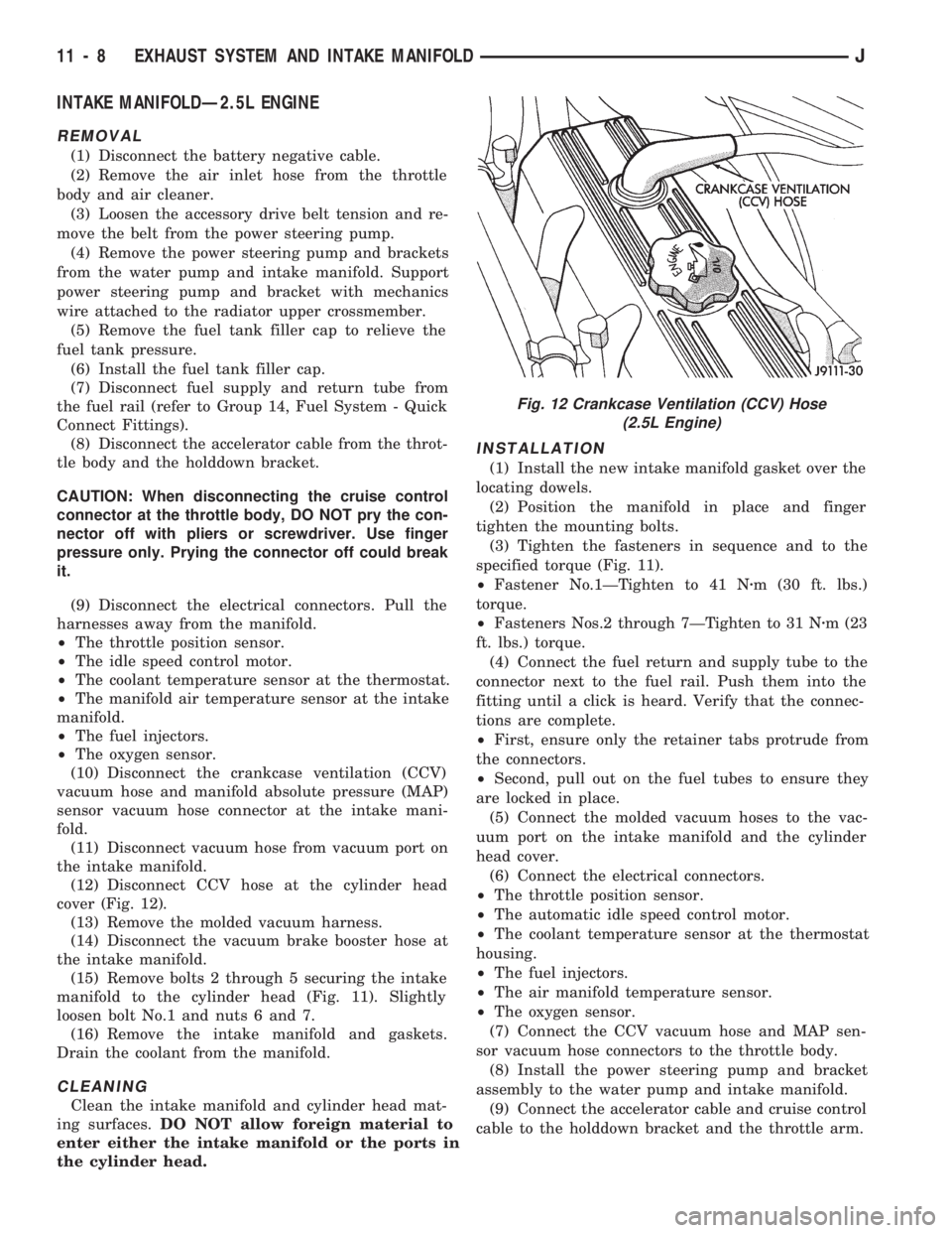
cover (Fig. 12).
(13) Remove the molded vacuum harness.
(14) Disconnect the vacuum brake booster hose at
the intake manifold.
(15) Remove bolts 2 through 5 securing the intake
manifold to the cylinder head (Fig. 11). Slightly
loosen bolt No.1 and nuts 6 and 7.
(16) Remove the intake manifold and gaskets.
Drain the coolant from the manifold.
CLEANING
Clean the intake manifold and cylinder head mat-
ing surfaces.DO NOT allow foreign material to
enter either the intake manifold or the ports in
the cylinder head.
INSTALLATION
(1) Install the new intake manifold gasket over the
locating dowels.
(2) Position the manifold in place and finger
tighten the mounting bolts.
(3) Tighten the fasteners in sequence and to the
specified torque (Fig. 11).
²Fastener No.1ÐTighten to 41 Nzm (30 ft. lbs.)
torque.
²Fasteners Nos.2 through 7ÐTighten to 31 Nzm (23
ft. lbs.) torque.
(4) Connect the fuel return and supply tube to the
connector next to the fuel rail. Push them into the
fitting until a click is heard. Verify that the connec-
tions are complete.
²First, ensure only the retainer tabs protrude from
the connectors.
²Second, pull out on the fuel tubes to ensure they
are locked in place.
(5) Connect the molded vacuum hoses to the vac-
uum port on the intake manifold and the cylinder
head cover.
(6) Connect the electrical connectors.
²The throttle position sensor.
²The automatic idle speed control motor.
²The coolant temperature sensor at the thermostat
housing.
²The fuel injectors.
²The air manifold temperature sensor.
²The oxygen sensor.
(7) Connect the CCV vacuum hose and MAP sen-
sor vacuum hose connectors to the throttle body.
(8) Install the power steering pump and bracket
assembly to the water pump and intake manifold.
(9) Connect the accelerator cable and cruise control
cable to the holddown bracket and the throttle arm.
Fig. 12 Crankcase Ventilation (CCV) Hose
(2.5L Engine)
11 - 8 EXHAUST SYSTEM AND INTAKE MANIFOLDJ
Page 946 of 1784
ets and bumper guards on the bumper rail. Tighten
hardware in the sequence indicated in Figure 7.
Tighten the locknuts with 20 Nzm (15 ft-lbs) torque.
Tighten bolts to 56 Nzm (41 ft-lbs) torque.(3) If not equipped with bumper guards, install the
bumper support brackets on the bumper rail. Tighten
bolts to 56 Nzm (41 ft-lbs) torque.
(4) If equipped with tow hooks, install the bolts
and nuts that attach them to the bumper support
brackets. Tighten nuts with 100 Nzm (74 ft-lbs)
torque.
(5) Install the bumper end caps on the bumper rail
(Fig. 8). Tighten nuts with 8 Nzm (72 in-lbs) torque.
(6) Install the license plate bracket on the bumper
rail. Tighten the nuts securely.
(7) If equipped, install the fog lamps on the
bumper rail. Tighten the nuts securely.
(8) If removed, install the vacuum reservoir(s) on
the bumper rail. Tighten the retaining screws and
bolts to 8 Nzm (72 in-lbs) torque.
(9) Position and support the bumper at the front of
the vehicle.
(10) Attach the bumper support brackets to the
right and left sillmembers and reinforcement brack-
ets. Tighten screws and bolts to 56 Nzm (41 ft-lbs)
torque.
(11) If equipped, install the Torx-head bolts and
locknuts that attach the tow hook straps to the un-
derbody sillmember. Tighten locknuts with 30 Nzm
(22 ft-lbs) torque.
Install the steering gear skid plate and screws
after the left tow hook strap has been installed.
(12) If equipped, connect the fog lamp wire harness
connectors.
(13) Connect the vacuum reservoir tube harness
connectors.
(14) Remove the bumper support.
FRONT TOW HOOKS
If a tow hook must be replaced or removed only for
service access, remove the nuts and bolts that attach
it to the bumper support bracket. When installing a
tow hook, tighten nuts with 100 Nzm (74 ft-lbs)
torque.
If a tow hook/bumper support bracket must be re-
placed, refer to the following removal and installa-
tion procedures.
REMOVAL
If equipped with a brush guard, refer to the
Brush Guard Removal within Group 23ÐBody
Components.
(1) If equipped, disconnect the fog lamp wire har-
ness connectors.
(2) Disconnect the vacuum reservoir tube harness
connectors.
(3) Support the bumper.
(4) Remove the bolts that attach the bumper sup-
port brackets to the right and left sillmembers.
(5) Remove the locknuts and Torx-head bolts that
attach the tow hook straps to the underbody sillmem-
ber.
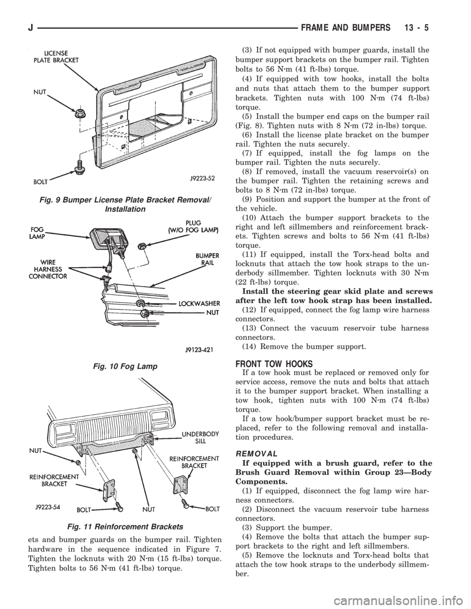
Fig. 9 Bumper License Plate Bracket Removal/
Installation
Fig. 10 Fog Lamp
Fig. 11 Reinforcement Brackets
JFRAME AND BUMPERS 13 - 5
Page 958 of 1784
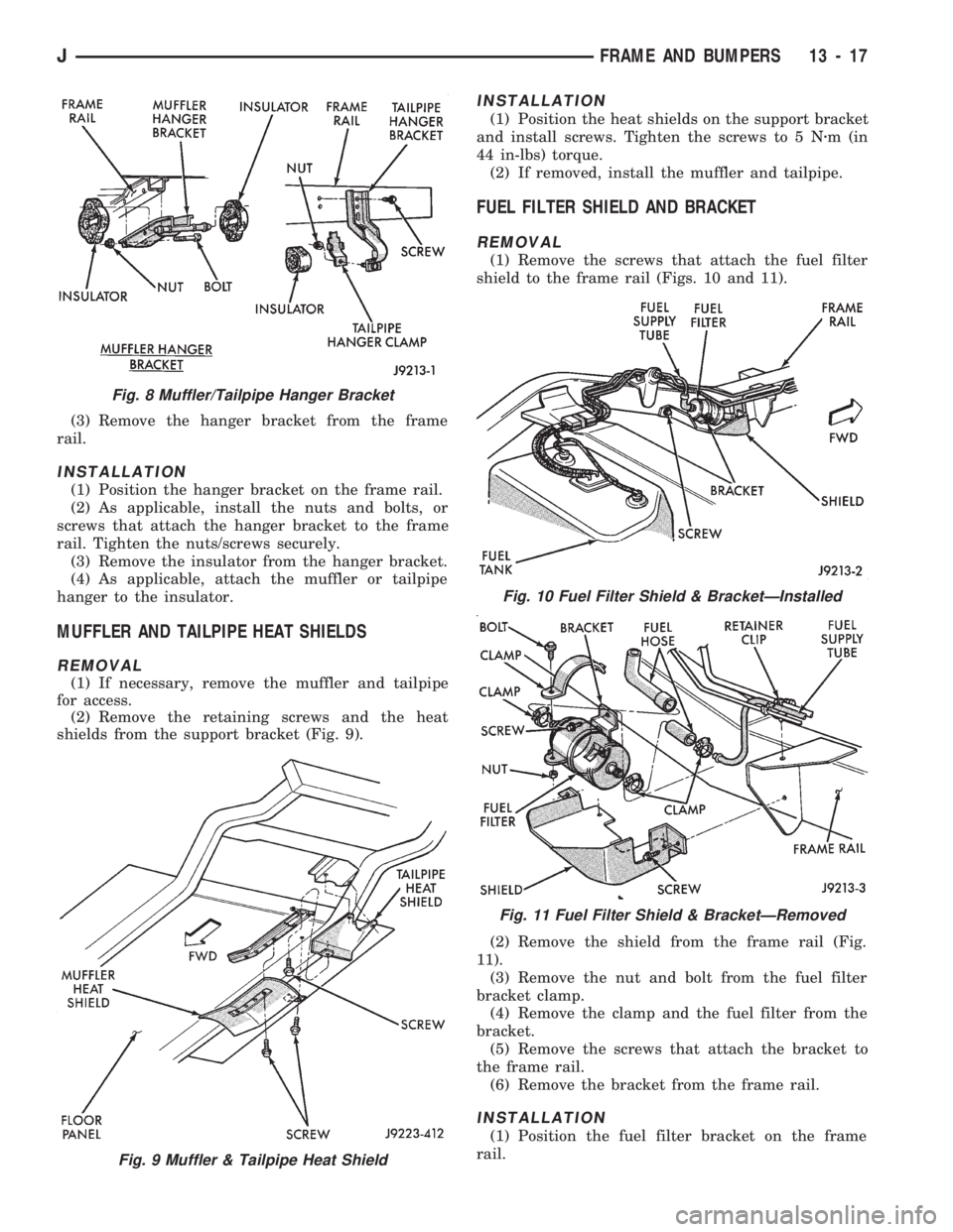
(3) Remove the hanger bracket from the frame
rail.
INSTALLATION
(1) Position the hanger bracket on the frame rail.
(2) As applicable, install the nuts and bolts, or
screws that attach the hanger bracket to the frame
rail. Tighten the nuts/screws securely.
(3) Remove the insulator from the hanger bracket.
(4) As applicable, attach the muffler or tailpipe
hanger to the insulator.
MUFFLER AND TAILPIPE HEAT SHIELDS
REMOVAL
(1) If necessary, remove the muffler and tailpipe
for access.
(2) Remove the retaining screws and the heat
shields from the support bracket (Fig. 9).
INSTALLATION
(1) Position the heat shields on the support bracket
and install screws. Tighten the screws to 5 Nzm (in
44 in-lbs) torque.
(2) If removed, install the muffler and tailpipe.
FUEL FILTER SHIELD AND BRACKET
REMOVAL
(1) Remove the screws that attach the fuel filter
shield to the frame rail (Figs. 10 and 11).
(2) Remove the shield from the frame rail (Fig.
11).
(3) Remove the nut and bolt from the fuel filter
bracket clamp.
(4) Remove the clamp and the fuel filter from the
bracket.
(5) Remove the screws that attach the bracket to
the frame rail.
(6) Remove the bracket from the frame rail.
INSTALLATION
(1) Position the fuel filter bracket on the frame
rail.
Fig. 8 Muffler/Tailpipe Hanger Bracket
Fig. 9 Muffler & Tailpipe Heat Shield
Fig. 10 Fuel Filter Shield & BracketÐInstalled
Fig. 11 Fuel Filter Shield & BracketÐRemoved
JFRAME AND BUMPERS 13 - 17
Page 959 of 1784
(2) Install the screws that attach the bracket to
the frame rail. Tighten the screws to 42 Nzm (31 ft-
lbs) torque.
(3) Install the fuel filter in the bracket.
(4) Position the clamp on the bracket and install
bolt and nut. Tighten the nut to 8 Nzm (72 in-lbs)
torque.
(5) Position the fuel filter shield from the frame
rail.
(6) Install the screws that attach the fuel filter
shield to the frame rail. Tighten the screws to 42
Nzm (31 ft-lbs) torque.
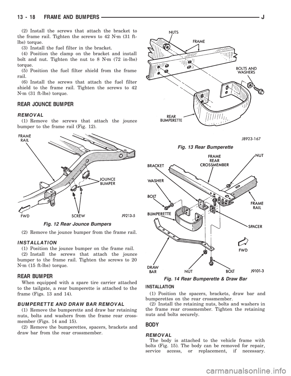
REAR JOUNCE BUMPER
REMOVAL
(1) Remove the screws that attach the jounce
bumper to the frame rail (Fig. 12).
(2) Remove the jounce bumper from the frame rail.
INSTALLATION
(1) Position the jounce bumper on the frame rail.
(2) Install the screws that attach the jounce
bumper to the frame rail. Tighten the screws to 20
Nzm (15 ft-lbs) torque.
REAR BUMPER
When equipped with a spare tire carrier attached
to the tailgate, a rear bumperette is attached to the
frame (Figs. 13 and 14).
BUMPERETTE AND DRAW BAR REMOVAL
(1) Remove the bumperette and draw bar retaining
nuts, bolts and washers from the frame rear cross-
member (Figs. 14 and 15).
(2) Remove the bumperettes, spacers, brackets and
draw bar from the rear crossmember.INSTALLATION
(1) Position the spacers, brackets, draw bar and
bumperettes on the rear crossmember.
(2) Install the retaining nuts, bolts and washers in
the frame rear crossmember. Tighten the retaining
nuts and bolts securely.
BODY
REMOVAL
The body is attached to the vehicle frame with
bolts (Fig. 15). The body can be removed for repair,
service access, or replacement, if necessary.
Fig. 12 Rear Jounce Bumpers
Fig. 13 Rear Bumperette
Fig. 14 Rear Bumperette & Draw Bar
13 - 18 FRAME AND BUMPERSJ
Page 964 of 1784
WARNING: WRAP SHOP TOWELS AROUND FUEL
HOSES TO ABSORB ANY FUEL SPILLAGE DURING
FUEL TANK REMOVAL.
(5) Disconnect fuel vent supply and return tubes
from fittings on fuel pump module.
(6) Disconnect fuel pump module electrical harness
connector from main harness.
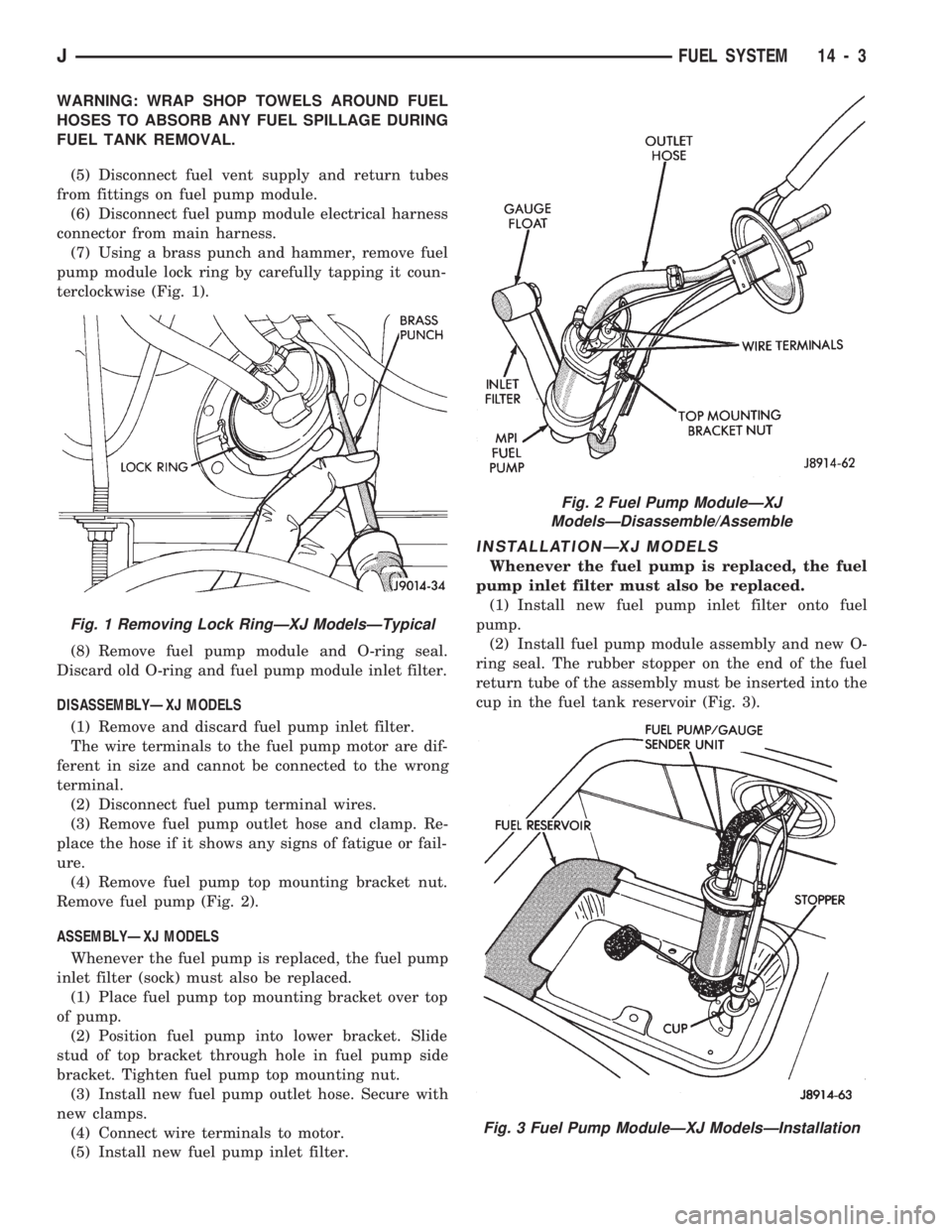
(7) Using a brass punch and hammer, remove fuel
pump module lock ring by carefully tapping it coun-
terclockwise (Fig. 1).
(8) Remove fuel pump module and O-ring seal.
Discard old O-ring and fuel pump module inlet filter.
DISASSEMBLYÐXJ MODELS
(1) Remove and discard fuel pump inlet filter.
The wire terminals to the fuel pump motor are dif-
ferent in size and cannot be connected to the wrong
terminal.
(2) Disconnect fuel pump terminal wires.
(3) Remove fuel pump outlet hose and clamp. Re-
place the hose if it shows any signs of fatigue or fail-
ure.
(4) Remove fuel pump top mounting bracket nut.
Remove fuel pump (Fig. 2).
ASSEMBLYÐXJ MODELS
Whenever the fuel pump is replaced, the fuel pump
inlet filter (sock) must also be replaced.
(1) Place fuel pump top mounting bracket over top
of pump.
(2) Position fuel pump into lower bracket. Slide
stud of top bracket through hole in fuel pump side
bracket. Tighten fuel pump top mounting nut.
(3) Install new fuel pump outlet hose. Secure with
new clamps.
(4) Connect wire terminals to motor.
(5) Install new fuel pump inlet filter.
INSTALLATIONÐXJ MODELS
Whenever the fuel pump is replaced, the fuel
pump inlet filter must also be replaced.
(1) Install new fuel pump inlet filter onto fuel
pump.
(2) Install fuel pump module assembly and new O-
ring seal. The rubber stopper on the end of the fuel
return tube of the assembly must be inserted into the
cup in the fuel tank reservoir (Fig. 3).
Fig. 1 Removing Lock RingÐXJ ModelsÐTypical
Fig. 2 Fuel Pump ModuleÐXJ
ModelsÐDisassemble/Assemble
Fig. 3 Fuel Pump ModuleÐXJ ModelsÐInstallation
JFUEL SYSTEM 14 - 3
Page 966 of 1784
(3) Install new fuel pump outlet hose. Secure with
new clamps.
(4) Connect wire terminals to motor.
(5) Install new fuel pump inlet filter.
INSTALLATIONÐYJ MODELS
(1) Install a new fuel pump inlet filter.
(2) Install fuel pump module assembly with a new
gasket between the assembly and tank. Tighten
mounting screws to 2 Nzm (18 in. lbs.) torque.
(3) Install fuel tank. Refer to Fuel Tank Installa-
tionÐYJ Models.
(4) Fill fuel tank. Install fuel tank cap.
(5) Install negative battery cable.
(6) Start vehicle and check for leaks.
FUEL PUMP ELECTRICAL CONTROL
For an electrical operational description of the fuel
pump, refer to the MFI SystemÐComponent Descrip-
tion/System Operation section of this group. See Au-
tomatic Shut Down (ASD) RelayÐPCM Output.
For the 1994 model year, the ballast resistor and
ballast resistor bypass relay are no longer used to
control the fuel pump circuit.
FUEL PRESSURE RELEASE PROCEDURE
WARNING: THE FUEL SYSTEM IS UNDER CON-
STANT FUEL PRESSURE (EVEN WITH THE ENGINE
OFF) OF APPROXIMATELY 131-269 KPA (19-39
PSI). THIS PRESSURE MUST BE RELEASED BE-
FORE SERVICING ANY FUEL SUPPLY OR FUEL RE-
TURN SYSTEM COMPONENT.
(1) Disconnect negative battery cable.
(2) Remove fuel tank filler neck cap to release fuel
tank pressure.
WARNING: DO NOT ALLOW FUEL TO SPILL ONTO
THE ENGINE INTAKE OR EXHAUST MANIFOLDS.
PLACE SHOP TOWELS UNDER AND AROUND THE
PRESSURE PORT TO ABSORB FUEL WHEN THE
PRESSURE IS RELEASED FROM THE FUEL RAIL.
WARNING: WEAR PROPER EYE PROTECTION
WHEN RELEASING FUEL SYSTEM PRESSURE.
(3) Remove protective cap from pressure test port
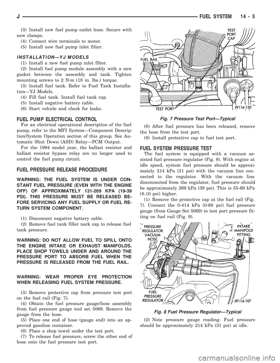
on the fuel rail (Fig. 7).
(4) Obtain the fuel pressure gauge/hose assembly
from fuel pressure gauge tool set 5069. Remove the
gauge from the hose.
(5) Place one end of hose (gauge end) into an ap-
proved gasoline container.
(6) Place a shop towel under the test port.
(7) To release fuel pressure, screw the other end of
hose onto the fuel pressure test port.(8) After fuel pressure has been released, remove
the hose from the test port.
(9) Install protective cap to fuel test port.
FUEL SYSTEM PRESSURE TEST
The fuel system is equipped with a vacuum as-
sisted fuel pressure regulator (Fig. 8). With engine at
idle speed, system fuel pressure should be approxi-
mately 214 kPa (31 psi) with the vacuum line con-
nected to the regulator. With the vacuum line
disconnected from the regulator, fuel pressure should
be approximately 269 kPa (39 psi). This is 55-69 kPa
(8-10 psi) higher.
(1) Remove the protective cap at the fuel rail (Fig.
7). Connect the 0-414 kPa (0-60 psi) fuel pressure
gauge (from Gauge Set 5069) to test port pressure fit-
ting on fuel rail (Fig. 9).
(2) Note pressure gauge reading. Fuel pressure
should be approximately 214 kPa (31 psi) at idle.
Fig. 7 Pressure Test PortÐTypical
Fig. 8 Fuel Pressure RegulatorÐTypical
JFUEL SYSTEM 14 - 5