1994 JEEP CHEROKEE ECU
[x] Cancel search: ECUPage 970 of 1784
(1) Place fuel filter in retaining strap with the
marked ends in the correct position.
(2) Install retaining strap bolt and tighten to 12
Nzm (106 in. lbs.) torque.
(3) Install inlet and outlet hoses and hose clamps.
For procedures, refer to Fuel Tubes/Lines/Hoses and
Clamps. Also refer to Quick-Connect Fittings. These
can be found in the Fuel Delivery System section of
this group.
(4) On YJ models, install fuel filter shield (Fig. 13).
(5) Lower vehicle.
(6) Connect negative battery cable.
(7) Start engine and check for leaks.
FUEL TUBES/LINES/HOSES AND CLAMPS
Also refer to the proceeding section on Quick-Con-
nect Fittings.
WARNING: THE FUEL SYSTEM IS UNDER A CON-
STANT PRESSURE (EVEN WITH THE ENGINE OFF).
BEFORE SERVICING ANY FUEL SYSTEM HOSES,
FITTINGS OR LINES, THE FUEL SYSTEM PRES-
SURE MUST BE RELEASED. REFER TO THE FUEL
PRESSURE RELEASE PROCEDURE IN THIS
GROUP.
Inspect all hose connections such as clamps, cou-
plings and fittings to make sure they are secure and
leaks are not present. The component should be re-
placed immediately if there is any evidence of degra-
dation that could result in failure.
Never attempt to repair a plastic fuel line/tube. Re-
place as necessary.
Avoid contact of any fuel tubes/hoses with other ve-
hicle components that could cause abrasions or scuff-
ing. Be sure that the plastic fuel lines/tubes are
properly routed to prevent pinching and to avoid heat
sources.
The lines/tubes/hoses used on fuel injected vehicles
are of a special construction. This is due to the
higher fuel pressures and the possibility of contami-
nated fuel in this system. If it is necessary to replace
these lines/tubes/hoses, only those marked EFM/EFI
may be used.
The hose clamps used to secure rubber hoses on
fuel injected vehicles are of a special rolled edge con-
struction. This construction is used to prevent the
edge of the clamp from cutting into the hose. Only
these rolled edge type clamps may be used in this
system. All other types of clamps may cut into the
hoses and cause high pressure fuel leaks.
Use new original equipment type hose clamps.
Tighten hose clamps to 1 Nzm (15 in. lbs.) torque.
QUICK-CONNECT FITTINGS
Also refer to the previous Fuel Tubes/Lines/Hoses
and Clamps section.Different types of quick-connect fittings are used to
attach various fuel system components. These are: a
single-tab type, a two-tab type or a plastic retainer
ring type.
SINGLE-TAB TYPE
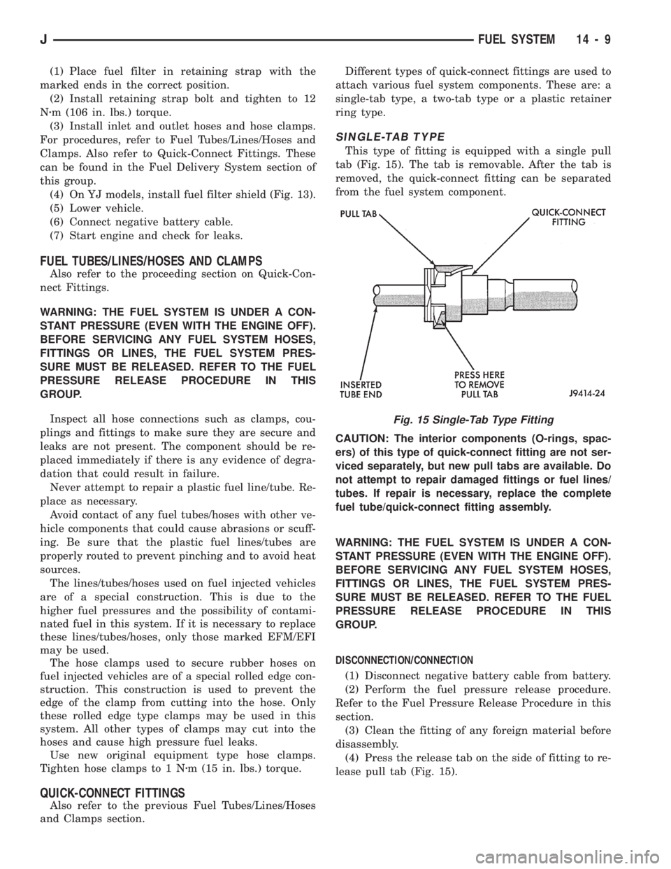
This type of fitting is equipped with a single pull
tab (Fig. 15). The tab is removable. After the tab is
removed, the quick-connect fitting can be separated
from the fuel system component.
CAUTION: The interior components (O-rings, spac-
ers) of this type of quick-connect fitting are not ser-
viced separately, but new pull tabs are available. Do
not attempt to repair damaged fittings or fuel lines/
tubes. If repair is necessary, replace the complete
fuel tube/quick-connect fitting assembly.
WARNING: THE FUEL SYSTEM IS UNDER A CON-
STANT PRESSURE (EVEN WITH THE ENGINE OFF).
BEFORE SERVICING ANY FUEL SYSTEM HOSES,
FITTINGS OR LINES, THE FUEL SYSTEM PRES-
SURE MUST BE RELEASED. REFER TO THE FUEL
PRESSURE RELEASE PROCEDURE IN THIS
GROUP.
DISCONNECTION/CONNECTION
(1) Disconnect negative battery cable from battery.
(2) Perform the fuel pressure release procedure.
Refer to the Fuel Pressure Release Procedure in this
section.
(3) Clean the fitting of any foreign material before
disassembly.
(4) Press the release tab on the side of fitting to re-
lease pull tab (Fig. 15).
Fig. 15 Single-Tab Type Fitting
JFUEL SYSTEM 14 - 9
Page 974 of 1784
REMOVALÐXJ MODELS
Perform the preceding Fuel System Pressure Re-
lease Procedure.
(1) Disconnect negative battery cable.
(2) Remove the fuel filler cap. Using an approved
portable gasoline siphon/storage tank, drain fuel
tank.
(3) Raise and support vehicle.
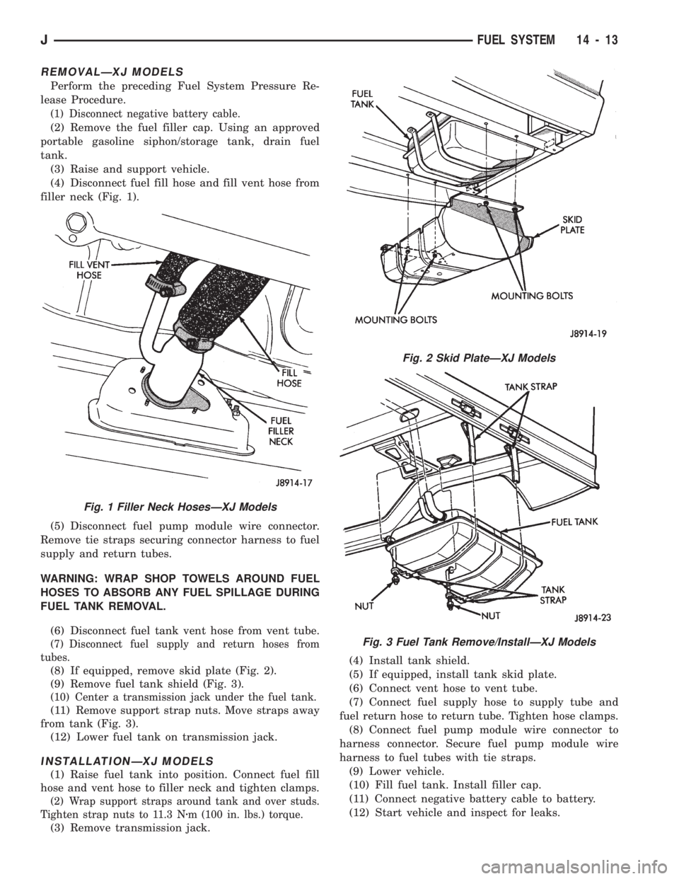
(4) Disconnect fuel fill hose and fill vent hose from
filler neck (Fig. 1).
(5) Disconnect fuel pump module wire connector.
Remove tie straps securing connector harness to fuel
supply and return tubes.
WARNING: WRAP SHOP TOWELS AROUND FUEL
HOSES TO ABSORB ANY FUEL SPILLAGE DURING
FUEL TANK REMOVAL.
(6) Disconnect fuel tank vent hose from vent tube.
(7) Disconnect fuel supply and return hoses from
tubes.
(8) If equipped, remove skid plate (Fig. 2).
(9) Remove fuel tank shield (Fig. 3).
(10) Center a transmission jack under the fuel tank.
(11) Remove support strap nuts. Move straps away
from tank (Fig. 3).
(12) Lower fuel tank on transmission jack.
INSTALLATIONÐXJ MODELS
(1) Raise fuel tank into position. Connect fuel fill
hose and vent hose to filler neck and tighten clamps.
(2) Wrap support straps around tank and over studs.
Tighten strap nuts to 11.3 Nzm (100 in. lbs.) torque.
(3) Remove transmission jack.(4) Install tank shield.
(5) If equipped, install tank skid plate.
(6) Connect vent hose to vent tube.
(7) Connect fuel supply hose to supply tube and
fuel return hose to return tube. Tighten hose clamps.
(8) Connect fuel pump module wire connector to
harness connector. Secure fuel pump module wire
harness to fuel tubes with tie straps.
(9) Lower vehicle.
(10) Fill fuel tank. Install filler cap.
(11) Connect negative battery cable to battery.
(12) Start vehicle and inspect for leaks.
Fig. 1 Filler Neck HosesÐXJ Models
Fig. 2 Skid PlateÐXJ Models
Fig. 3 Fuel Tank Remove/InstallÐXJ Models
JFUEL SYSTEM 14 - 13
Page 975 of 1784
REMOVALÐYJ MODELS
WARNING: EXTINGUISH ALL TOBACCO SMOKING
PRODUCTS BEFORE SERVICING THE FUEL SYS-
TEM. KEEP OPEN FLAME AWAY FROM FUEL SYS-
TEM COMPONENTS.
(1) Disconnect negative battery cable.
(2) Remove the fuel filler cap. Using an approved por-
table gasoline siphon/storage tank, drain fuel tank.
(3) Raise and support vehicle.
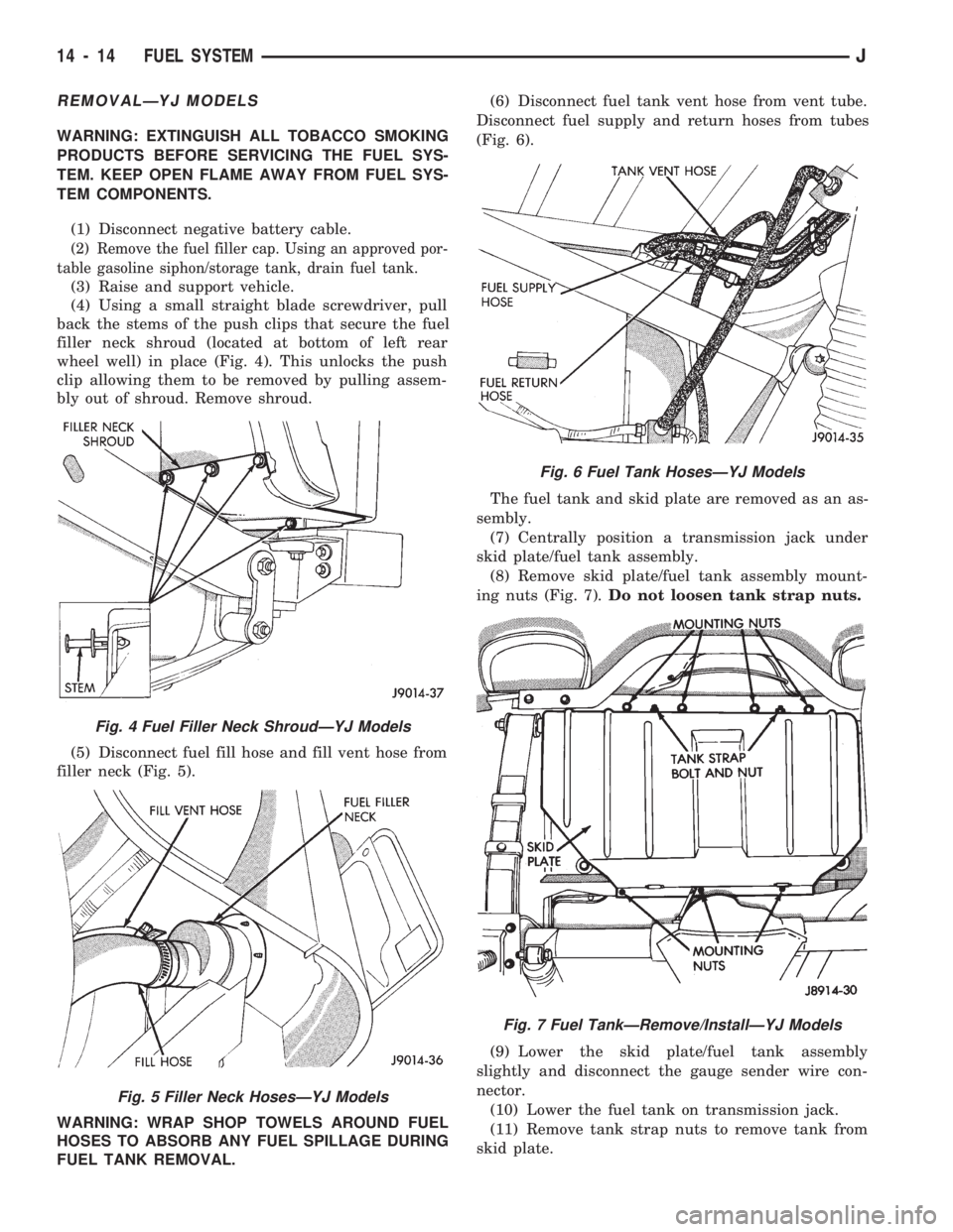
(4) Using a small straight blade screwdriver, pull
back the stems of the push clips that secure the fuel
filler neck shroud (located at bottom of left rear
wheel well) in place (Fig. 4). This unlocks the push
clip allowing them to be removed by pulling assem-
bly out of shroud. Remove shroud.
(5) Disconnect fuel fill hose and fill vent hose from
filler neck (Fig. 5).
WARNING: WRAP SHOP TOWELS AROUND FUEL
HOSES TO ABSORB ANY FUEL SPILLAGE DURING
FUEL TANK REMOVAL.(6) Disconnect fuel tank vent hose from vent tube.
Disconnect fuel supply and return hoses from tubes
(Fig. 6).
The fuel tank and skid plate are removed as an as-
sembly.
(7) Centrally position a transmission jack under
skid plate/fuel tank assembly.
(8) Remove skid plate/fuel tank assembly mount-
ing nuts (Fig. 7).Do not loosen tank strap nuts.
(9) Lower the skid plate/fuel tank assembly
slightly and disconnect the gauge sender wire con-
nector.
(10) Lower the fuel tank on transmission jack.
(11) Remove tank strap nuts to remove tank from
skid plate.
Fig. 4 Fuel Filler Neck ShroudÐYJ Models
Fig. 5 Filler Neck HosesÐYJ Models
Fig. 6 Fuel Tank HosesÐYJ Models
Fig. 7 Fuel TankÐRemove/InstallÐYJ Models
14 - 14 FUEL SYSTEMJ
Page 1018 of 1784
REMOVAL
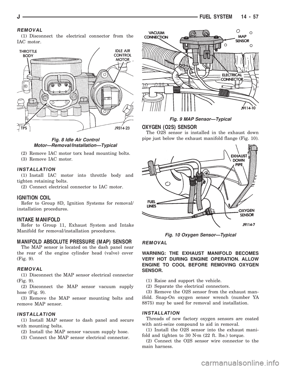
(1) Disconnect the electrical connector from the
IAC motor.
(2) Remove IAC motor torx head mounting bolts.
(3) Remove IAC motor.
INSTALLATION
(1) Install IAC motor into throttle body and
tighten retaining bolts.
(2) Connect electrical connector to IAC motor.
IGNITION COIL
Refer to Group 8D, Ignition Systems for removal/
installation procedures.
INTAKE MANIFOLD
Refer to Group 11, Exhaust System and Intake
Manifold for removal/installation procedures.
MANIFOLD ABSOLUTE PRESSURE (MAP) SENSOR
The MAP sensor is located on the dash panel near
the rear of the engine cylinder head (valve) cover
(Fig. 9).
REMOVAL
(1) Disconnect the MAP sensor electrical connector
(Fig. 9).
(2) Disconnect the MAP sensor vacuum supply
hose (Fig. 9).
(3) Remove the MAP sensor mounting bolts and
remove MAP sensor.
INSTALLATION
(1) Install MAP sensor to dash panel and secure
with mounting bolts.
(2) Install the MAP sensor vacuum supply hose.
(3) Connect the MAP sensor electrical connector.
OXYGEN (O2S) SENSOR
The O2S sensor is installed in the exhaust down
pipe just below the exhaust manifold flange (Fig. 10).
REMOVAL
WARNING: THE EXHAUST MANIFOLD BECOMES
VERY HOT DURING ENGINE OPERATION. ALLOW
ENGINE TO COOL BEFORE REMOVING OXYGEN
SENSOR.
(1) Raise and support the vehicle.
(2) Separate the electrical connectors.
(3) Remove the O2S sensor from the exhaust man-
ifold. Snap-On oxygen sensor wrench (number YA
8875) may be used for removal and installation.
INSTALLATION
Threads of new factory oxygen sensors are coated
with anti-seize compound to aid in removal.
(1) Install the O2S sensor into the exhaust mani-
fold and tighten to 30 Nzm (22 ft. lbs.) torque.
(2) Connect the O2S sensor wire connector to the
main harness.
Fig. 8 Idle Air Control
MotorÐRemoval/InstallationÐTypical
Fig. 9 MAP SensorÐTypical
Fig. 10 Oxygen SensorÐTypical
JFUEL SYSTEM 14 - 57
Page 1065 of 1784
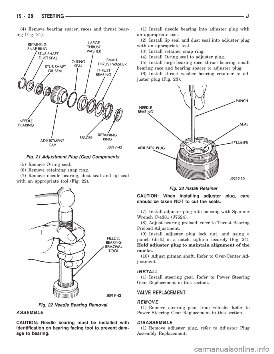
(4) Remove bearing spacer, races and thrust bear-
ing (Fig. 21).
(5) Remove O-ring seal.
(6) Remove retaining snap ring.
(7) Remove needle bearing, dust seal and lip seal
with an appropriate tool (Fig. 22).
ASSEMBLE
CAUTION: Needle bearing must be installed with
identification on bearing facing tool to prevent dam-
age to bearing.(1) Install needle bearing into adjuster plug with
an appropriate tool.
(2) Install lip seal and dust seal into adjuster plug
with an appropriate tool.
(3) Install retainer snap ring.
(4) Install O-ring seal to adjuster plug.
(5) Install large bearing race, thrust bearing, small
bearing race and bearing spacer to adjuster plug.
(6) Install thrust washer bearing retainer to ad-
juster plug (Fig. 23).
CAUTION: When installing adjuster plug, care
should be taken NOT to cut the seals.
(7) Install adjuster plug into housing with Spanner
Wrench C-4381 (J7624).
(8) Adjust bearing preload, refer to Thrust Bearing
Preload Adjustment.
(9) Install adjuster plug lock nut, and using a
punch (drift) in a notch, tighten securely (Fig. 24).
Hold adjuster plug to maintain alignment of the
marks.
(10) Adjust pitman shaft. Refer to Over-Center Ad-
justment.
INSTALL
(1) Install steering gear. Refer to Power Steering
Gear Replacement in this section.
VALVE REPLACEMENT
REMOVE
(1) Remove steering gear from vehicle. Refer to
Power Steering Gear Replacement in this section.
DISASSEMBLE
(1) Remove adjuster plug, refer to Adjuster Plug
Assembly Replacement.
Fig. 21 Adjustment Plug (Cap) Components
Fig. 22 Needle Bearing Removal
Fig. 23 Install Retainer
19 - 28 STEERINGJ
Page 1095 of 1784
(8) Align the turn signal switch in the housing and
secure the switch with the attaching screws. Tighten
the screws to 4 Nzm (35 in. lbs.) torque.
(9) Install the dimmer switch actuator arm.
Tighten the attaching screws to 4 Nzm (35 in. lbs.)
torque.
(10) If equipped, install the cruise control wire har-
ness. Install the turn signal stalk by pushing it
straight into the column.
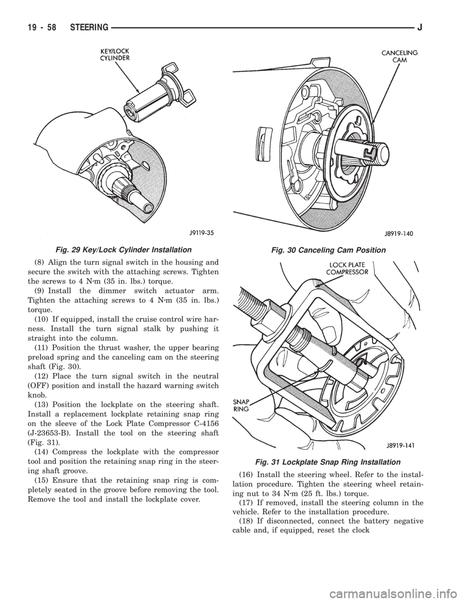
(11) Position the thrust washer, the upper bearing
preload spring and the canceling cam on the steering
shaft (Fig. 30).
(12) Place the turn signal switch in the neutral
(OFF) position and install the hazard warning switch
knob.
(13) Position the lockplate on the steering shaft.
Install a replacement lockplate retaining snap ring
on the sleeve of the Lock Plate Compressor C-4156
(J-23653-B). Install the tool on the steering shaft
(Fig. 31).
(14) Compress the lockplate with the compressor
tool and position the retaining snap ring in the steer-
ing shaft groove.
(15) Ensure that the retaining snap ring is com-
pletely seated in the groove before removing the tool.
Remove the tool and install the lockplate cover.(16) Install the steering wheel. Refer to the instal-
lation procedure. Tighten the steering wheel retain-
ing nut to 34 Nzm (25 ft. lbs.) torque.
(17) If removed, install the steering column in the
vehicle. Refer to the installation procedure.
(18) If disconnected, connect the battery negative
cable and, if equipped, reset the clock
Fig. 30 Canceling Cam Position
Fig. 31 Lockplate Snap Ring Installation
Fig. 29 Key/Lock Cylinder Installation
19 - 58 STEERINGJ
Page 1115 of 1784
(6) Remove slave cylinder from clutch housing.
(7) Disconnect transmission shift lever as follows:
(a) Lower transmission-transfer case assembly ap-
proximately 7-8 cm (3 in.) for access to shift lever.
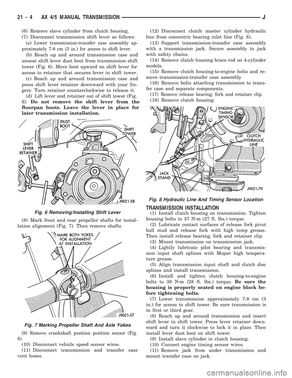
(b) Reach up and around transmission case and
unseat shift lever dust boot from transmission shift
tower (Fig. 6). Move boot upward on shift lever for
access to retainer that secures lever in shift tower.
(c) Reach up and around transmission case and
press shift lever retainer downward with your fin-
gers. Turn retainer counterclockwise to release it.
(d) Lift lever and retainer out of shift tower (Fig.
6).Do not remove the shift lever from the
floorpan boots. Leave the lever in place for
later transmission installation.
(8) Mark front and rear propeller shafts for instal-
lation alignment (Fig. 7). Then remove shafts.
(9) Remove crankshaft position position sensor (Fig.
8).
(10) Disconnect vehicle speed sensor wires.
(11) Disconnect transmission and transfer case
vent hoses.(12) Disconnect clutch master cylinder hydraulic
line from concentric bearing inlet line (Fig. 8).
(13) Support transmission-transfer case assembly
with a transmission jack. Secure assembly to jack
with safety chains.
(14) Remove clutch housing brace rod on 4-cylinder
models.
(15) Remove clutch housing-to-engine bolts and re-
move transmission-transfer case assembly.
(16) Remove bolts attaching transmission to trans-
fer case and separate components.
(17) Remove release bearing, fork and retainer clip.
(18) Remove clutch housing.
TRANSMISSION INSTALLATION
(1) Install clutch housing on transmission. Tighten
housing bolts to 37 Nzm (27 ft. lbs.) torque.
(2) Lubricate contact surfaces of release fork pivot
ball stud and release fork with high temp grease.
Then install release bearing, fork and retainer clip.
(3) Mount transmission on transmission jack.
(4) Lightly lubricate pilot bearing and transmis-
sion input shaft splines with Mopar high tempera-
ture grease.
(5) Align transmission input shaft and clutch disc
splines and install transmission.
(6) Install and tighten clutch housing-to-engine
bolts to 38 Nzm (28 ft. lbs.) torque.Be sure the
housing is properly seated on engine block be-
fore tightening bolts.
(7) Lower transmission approximately 7-8 cm (3
in.) for access to shift tower. Be sure transmission is
in first or third gear.
(8) Reach up and around transmission and insert
shift lever in shift tower. Press lever retainer down-
ward and turn it clockwise to lock it in place. Then
install lever dust boot on shift tower.
(9) Install slave cylinder in clutch housing.
(10) Connect engine timing sensor wires.
(11) Remove jack from under transmission and
mount transfer case on jack.Fig. 6 Removing/Installing Shift Lever
Fig. 7 Marking Propeller Shaft And Axle Yokes
Fig. 8 Hydraulic Line And Timing Sensor Location
21 - 4 AX 4/5 MANUAL TRANSMISSIONJ
Page 1127 of 1784
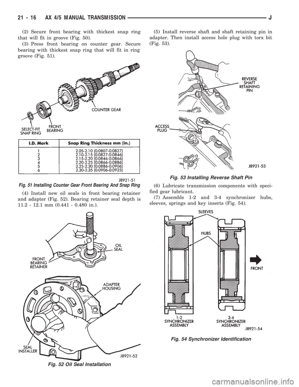
(2) Secure front bearing with thickest snap ring
that will fit in groove (Fig. 50).
(3) Press front bearing on counter gear. Secure
bearing with thickest snap ring that will fit in ring
groove (Fig. 51).
(4) Install new oil seals in front bearing retainer
and adapter (Fig. 52). Bearing retainer seal depth is
11.2 - 12.1 mm (0.441 - 0.480 in.).(5) Install reverse shaft and shaft retaining pin in
adapter. Then install access hole plug with torx bit
(Fig. 53).
(6) Lubricate transmission components with speci-
fied gear lubricant.
(7) Assemble 1-2 and 3-4 synchronizer hubs,
sleeves, springs and key inserts (Fig. 54).
Fig. 51 Installing Counter Gear Front Bearing And Snap Ring
Fig. 52 Oil Seal Installation
Fig. 53 Installing Reverse Shaft Pin
Fig. 54 Synchronizer Identification
21 - 16 AX 4/5 MANUAL TRANSMISSIONJ