1994 JEEP CHEROKEE ECU
[x] Cancel search: ECUPage 1146 of 1784
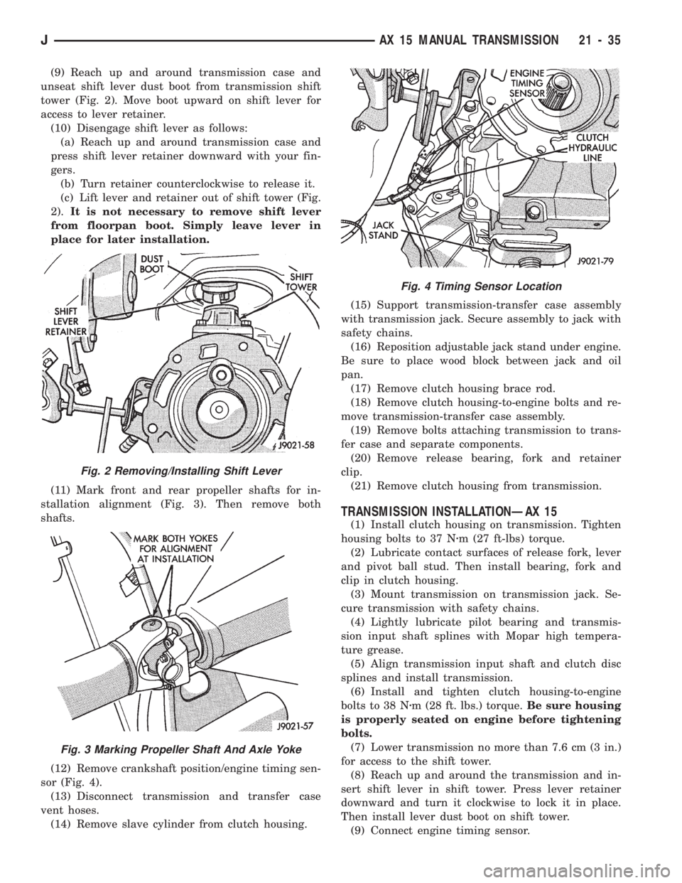
(9) Reach up and around transmission case and
unseat shift lever dust boot from transmission shift
tower (Fig. 2). Move boot upward on shift lever for
access to lever retainer.
(10) Disengage shift lever as follows:
(a) Reach up and around transmission case and
press shift lever retainer downward with your fin-
gers.
(b) Turn retainer counterclockwise to release it.
(c) Lift lever and retainer out of shift tower (Fig.
2).It is not necessary to remove shift lever
from floorpan boot. Simply leave lever in
place for later installation.
(11) Mark front and rear propeller shafts for in-
stallation alignment (Fig. 3). Then remove both
shafts.
(12) Remove crankshaft position/engine timing sen-
sor (Fig. 4).
(13) Disconnect transmission and transfer case
vent hoses.
(14) Remove slave cylinder from clutch housing.(15) Support transmission-transfer case assembly
with transmission jack. Secure assembly to jack with
safety chains.
(16) Reposition adjustable jack stand under engine.
Be sure to place wood block between jack and oil
pan.
(17) Remove clutch housing brace rod.
(18) Remove clutch housing-to-engine bolts and re-
move transmission-transfer case assembly.
(19) Remove bolts attaching transmission to trans-
fer case and separate components.
(20) Remove release bearing, fork and retainer
clip.
(21) Remove clutch housing from transmission.
TRANSMISSION INSTALLATIONÐAX 15
(1) Install clutch housing on transmission. Tighten
housing bolts to 37 Nzm (27 ft-lbs) torque.
(2) Lubricate contact surfaces of release fork, lever
and pivot ball stud. Then install bearing, fork and
clip in clutch housing.
(3) Mount transmission on transmission jack. Se-
cure transmission with safety chains.
(4) Lightly lubricate pilot bearing and transmis-
sion input shaft splines with Mopar high tempera-
ture grease.
(5) Align transmission input shaft and clutch disc
splines and install transmission.
(6) Install and tighten clutch housing-to-engine
bolts to 38 Nzm (28 ft. lbs.) torque.Be sure housing
is properly seated on engine before tightening
bolts.
(7) Lower transmission no more than 7.6 cm (3 in.)
for access to the shift tower.
(8) Reach up and around the transmission and in-
sert shift lever in shift tower. Press lever retainer
downward and turn it clockwise to lock it in place.
Then install lever dust boot on shift tower.
(9) Connect engine timing sensor.
Fig. 2 Removing/Installing Shift Lever
Fig. 3 Marking Propeller Shaft And Axle Yoke
Fig. 4 Timing Sensor Location
JAX 15 MANUAL TRANSMISSION 21 - 35
Page 1152 of 1784
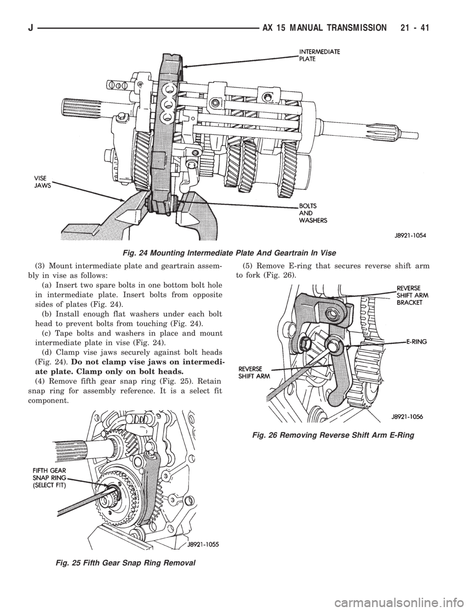
(3) Mount intermediate plate and geartrain assem-
bly in vise as follows:
(a) Insert two spare bolts in one bottom bolt hole
in intermediate plate. Insert bolts from opposite
sides of plates (Fig. 24).
(b) Install enough flat washers under each bolt
head to prevent bolts from touching (Fig. 24).
(c) Tape bolts and washers in place and mount
intermediate plate in vise (Fig. 24).
(d) Clamp vise jaws securely against bolt heads
(Fig. 24).Do not clamp vise jaws on intermedi-
ate plate. Clamp only on bolt heads.
(4) Remove fifth gear snap ring (Fig. 25). Retain
snap ring for assembly reference. It is a select fit
component.(5) Remove E-ring that secures reverse shift arm
to fork (Fig. 26).
Fig. 24 Mounting Intermediate Plate And Geartrain In Vise
Fig. 25 Fifth Gear Snap Ring Removal
Fig. 26 Removing Reverse Shift Arm E-Ring
JAX 15 MANUAL TRANSMISSION 21 - 41
Page 1163 of 1784
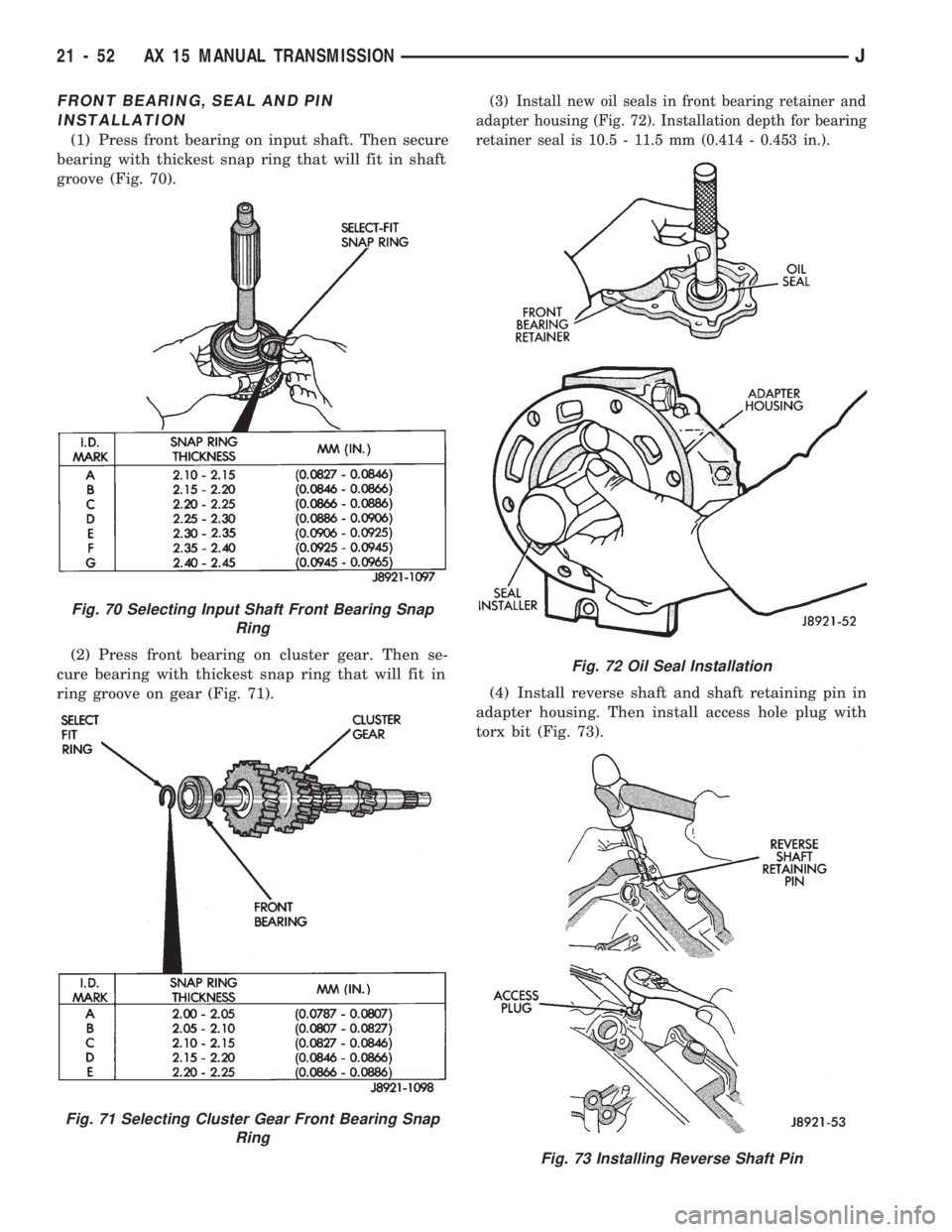
FRONT BEARING, SEAL AND PIN
INSTALLATION
(1) Press front bearing on input shaft. Then secure
bearing with thickest snap ring that will fit in shaft
groove (Fig. 70).
(2) Press front bearing on cluster gear. Then se-
cure bearing with thickest snap ring that will fit in
ring groove on gear (Fig. 71).
(3) Install new oil seals in front bearing retainer and
adapter housing (Fig. 72). Installation depth for bearing
retainer seal is 10.5 - 11.5 mm (0.414 - 0.453 in.).
(4) Install reverse shaft and shaft retaining pin in
adapter housing. Then install access hole plug with
torx bit (Fig. 73).
Fig. 70 Selecting Input Shaft Front Bearing Snap
Ring
Fig. 71 Selecting Cluster Gear Front Bearing Snap
Ring
Fig. 72 Oil Seal Installation
Fig. 73 Installing Reverse Shaft Pin
21 - 52 AX 15 MANUAL TRANSMISSIONJ
Page 1169 of 1784
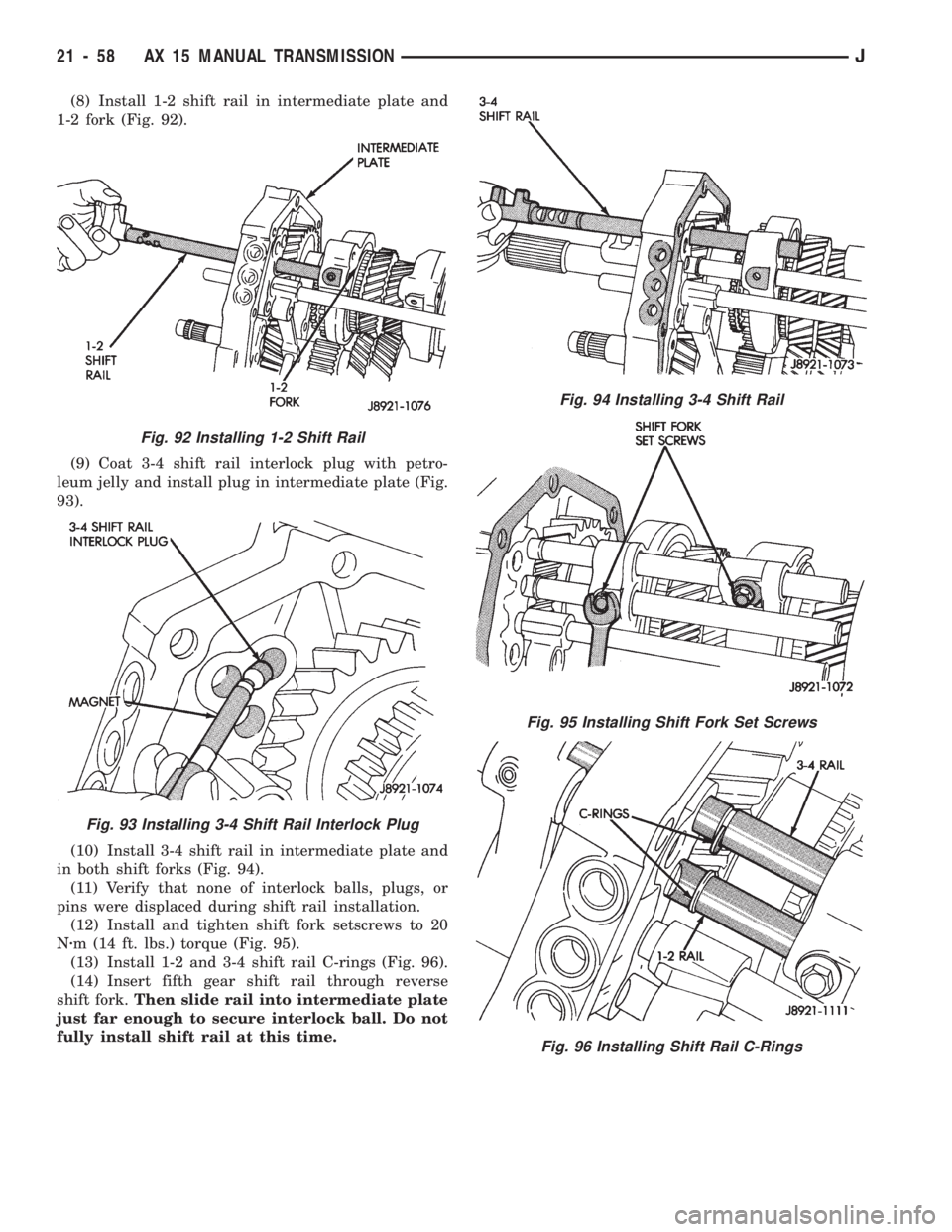
(8) Install 1-2 shift rail in intermediate plate and
1-2 fork (Fig. 92).
(9) Coat 3-4 shift rail interlock plug with petro-
leum jelly and install plug in intermediate plate (Fig.
93).
(10) Install 3-4 shift rail in intermediate plate and
in both shift forks (Fig. 94).
(11) Verify that none of interlock balls, plugs, or
pins were displaced during shift rail installation.
(12) Install and tighten shift fork setscrews to 20
Nzm (14 ft. lbs.) torque (Fig. 95).
(13) Install 1-2 and 3-4 shift rail C-rings (Fig. 96).
(14) Insert fifth gear shift rail through reverse
shift fork.Then slide rail into intermediate plate
just far enough to secure interlock ball. Do not
fully install shift rail at this time.
Fig. 94 Installing 3-4 Shift Rail
Fig. 95 Installing Shift Fork Set Screws
Fig. 96 Installing Shift Rail C-Rings
Fig. 92 Installing 1-2 Shift Rail
Fig. 93 Installing 3-4 Shift Rail Interlock Plug
21 - 58 AX 15 MANUAL TRANSMISSIONJ
Page 1171 of 1784
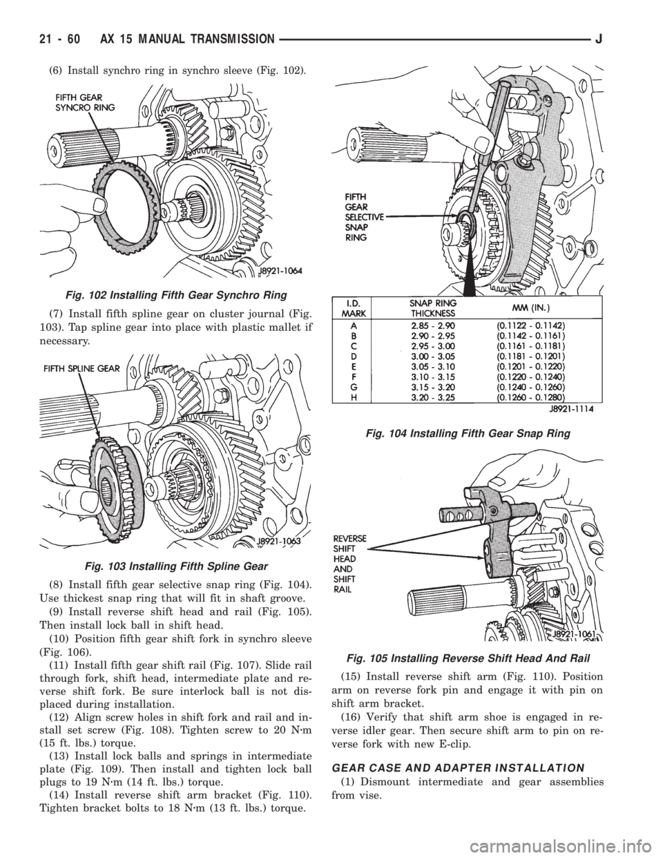
(6) Install synchro ring in synchro sleeve (Fig. 102).
(7) Install fifth spline gear on cluster journal (Fig.
103). Tap spline gear into place with plastic mallet if
necessary.
(8) Install fifth gear selective snap ring (Fig. 104).
Use thickest snap ring that will fit in shaft groove.
(9) Install reverse shift head and rail (Fig. 105).
Then install lock ball in shift head.
(10) Position fifth gear shift fork in synchro sleeve
(Fig. 106).
(11) Install fifth gear shift rail (Fig. 107). Slide rail
through fork, shift head, intermediate plate and re-
verse shift fork. Be sure interlock ball is not dis-
placed during installation.
(12) Align screw holes in shift fork and rail and in-
stall set screw (Fig. 108). Tighten screw to 20 Nzm
(15 ft. lbs.) torque.
(13) Install lock balls and springs in intermediate
plate (Fig. 109). Then install and tighten lock ball
plugs to 19 Nzm (14 ft. lbs.) torque.
(14) Install reverse shift arm bracket (Fig. 110).
Tighten bracket bolts to 18 Nzm (13 ft. lbs.) torque.(15) Install reverse shift arm (Fig. 110). Position
arm on reverse fork pin and engage it with pin on
shift arm bracket.
(16) Verify that shift arm shoe is engaged in re-
verse idler gear. Then secure shift arm to pin on re-
verse fork with new E-clip.
GEAR CASE AND ADAPTER INSTALLATION
(1) Dismount intermediate and gear assemblies
from vise.
Fig. 104 Installing Fifth Gear Snap Ring
Fig. 105 Installing Reverse Shift Head And Rail
Fig. 102 Installing Fifth Gear Synchro Ring
Fig. 103 Installing Fifth Spline Gear
21 - 60 AX 15 MANUAL TRANSMISSIONJ
Page 1173 of 1784
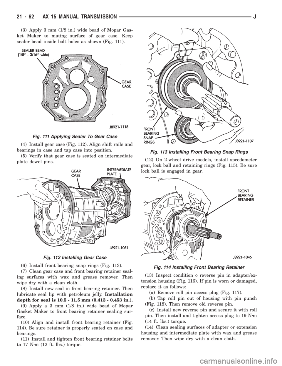
(3) Apply 3 mm (1/8 in.) wide bead of Mopar Gas-
ket Maker to mating surface of gear case. Keep
sealer bead inside bolt holes as shown (Fig. 111).
(4) Install gear case (Fig. 112). Align shift rails and
bearings in case and tap case into position.
(5) Verify that gear case is seated on intermediate
plate dowel pins.
(6) Install front bearing snap rings (Fig. 113).
(7) Clean gear case and front bearing retainer seal-
ing surfaces with wax and grease remover. Then
wipe dry with a clean cloth.
(8) Install new seal in front bearing retainer. Then
lubricate seal lip with petroleum jelly.Installation
depth for seal is 10.5 - 11.5 mm (0.413 - 0.453 in.).
(9) Applya3mm(1/8 in.) wide bead of Mopar
Gasket Maker to front bearing retainer sealing sur-
face.
(10) Align and install front bearing retainer (Fig.
114). Be sure retainer is properly seated on case and
bearings.
(11) Install and tighten front bearing retainer bolts
to 17 Nzm (12 ft. lbs.) torque.(12) On 2-wheel drive models, install speedometer
gear, lock ball and retaining rings (Fig. 115). Be sure
lock ball is engaged in gear.
(13) Inspect condition o reverse pin in adapter/ex-
tension housing (Fig. 116). If pin is worn or damaged,
replace it as follows:
(a) Remove roll pin access plug (Fig. 117).
(b) Tap roll pin out of housing with pin punch
(Fig. 118). Then remove old reverse pin.
(c) Install new reverse pin and secure it with roll
pin. Then install and tighten access plug to 19 Nzm
(14 ft. lbs.) torque.
(14) Clean sealing surfaces of adapter or extension
housing and intermediate plate with wax and grease
remover. Then wipe dry with a clean cloth.
Fig. 111 Applying Sealer To Gear Case
Fig. 112 Installing Gear Case
Fig. 113 Installing Front Bearing Snap Rings
Fig. 114 Installing Front Bearing Retainer
21 - 62 AX 15 MANUAL TRANSMISSIONJ
Page 1185 of 1784
Some suspected converter housing fluid leaks may
not be leaks at all. Residual fluid in the housing, or
excess fluid spilled during factory fill or refill after
repair can be mistaken for a leak. In addition, a rear
main seal leak can also be mistaken for a pump seal
leak if care is exercised.
Converter housing leaks have several potential
sources. Through careful observation, a leak source
can be identified before removing the transmission
for repair.
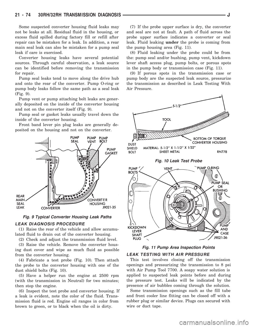
Pump seal leaks tend to move along the drive hub
and onto the rear of the converter. Pump O-ring or
pump body leaks follow the same path as a seal leak
(Fig. 9).
Pump vent or pump attaching bolt leaks are gener-
ally deposited on the inside of the converter housing
and not on the converter itself (Fig. 9).
Pump seal or gasket leaks usually travel down the
inside of the converter housing.
Front band lever pin plug leaks are generally de-
posited on the housing and not on the converter.
LEAK DIAGNOSIS PROCEDURE
(1) Raise the rear of the vehicle and allow accumu-
lated fluid to drain out of the converter housing.
(2) Check and adjust the transmission fluid level.
(3) Raise the vehicle. Remove the converter hous-
ing dust cover and wipe as much fluid as possible
from the converter housing.
(4) Fabricate a test probe (Fig. 10). Then attach
the probe to the converter housing with one of the
dust shield bolts (Fig. 10).
(5) Have a helper run the engine at 2500 rpm
(with the transmission in Neutral) for two minutes;
then stop the engine.
(6) Inspect the test probe and converter housing. If
a leak is evident, note the color of the fluid. Trans-
mission fluid is red. Engine oil ranges in color from
brown to green, or to black when the oil is dirty.(7) If the probe upper surface is dry, the converter
and seal are not at fault. A path of fluid across the
probe upper surface indicates a converter or seal
leak. Fluid leakingunderthe probe is coming from
the pump housing area (Fig. 11).
(8) Fluid leaking under the probe could be from
the: pump seal and/or bushing, pump vent, kickdown
lever shaft access plug, pump bolts, or porous spots
in the pump body or transmission case (Fig. 11).
(9) If porous spots in the transmission case or
pump body are the suspected leak source, pressurize
the transmission as described in Leak Testing With
Air Pressure.
LEAK TESTING WITH AIR PRESSURE
This test involves closing off the transmission
openings and pressurizing the transmission to 8 psi
with Air Pump Tool 7700. A soapy water solution is
applied to suspected leak points before and during
the pressure test. Leaks will be indicated by the
presence of air bubbles coming through the solution.
Some transmission openings such as the fill tube
and front cooler line fitting can be closed off with a
rubber plug or similar device. Plugs can secured with
wire or duct tape.
Fig. 9 Typical Converter Housing Leak Paths
Fig. 10 Leak Test Probe
Fig. 11 Pump Area Inspection Points
21 - 74 30RH/32RH TRANSMISSION DIAGNOSISJ
Page 1186 of 1784
The transmission rear output shaft opening is
closed off simply by leaving the transfer case bolted
in place. However, if the transfer case has been re-
moved, a shipping plug can used to close off this
opening.
The torque converter hub opening in the pump and
the pump vent require special tools to close them off.
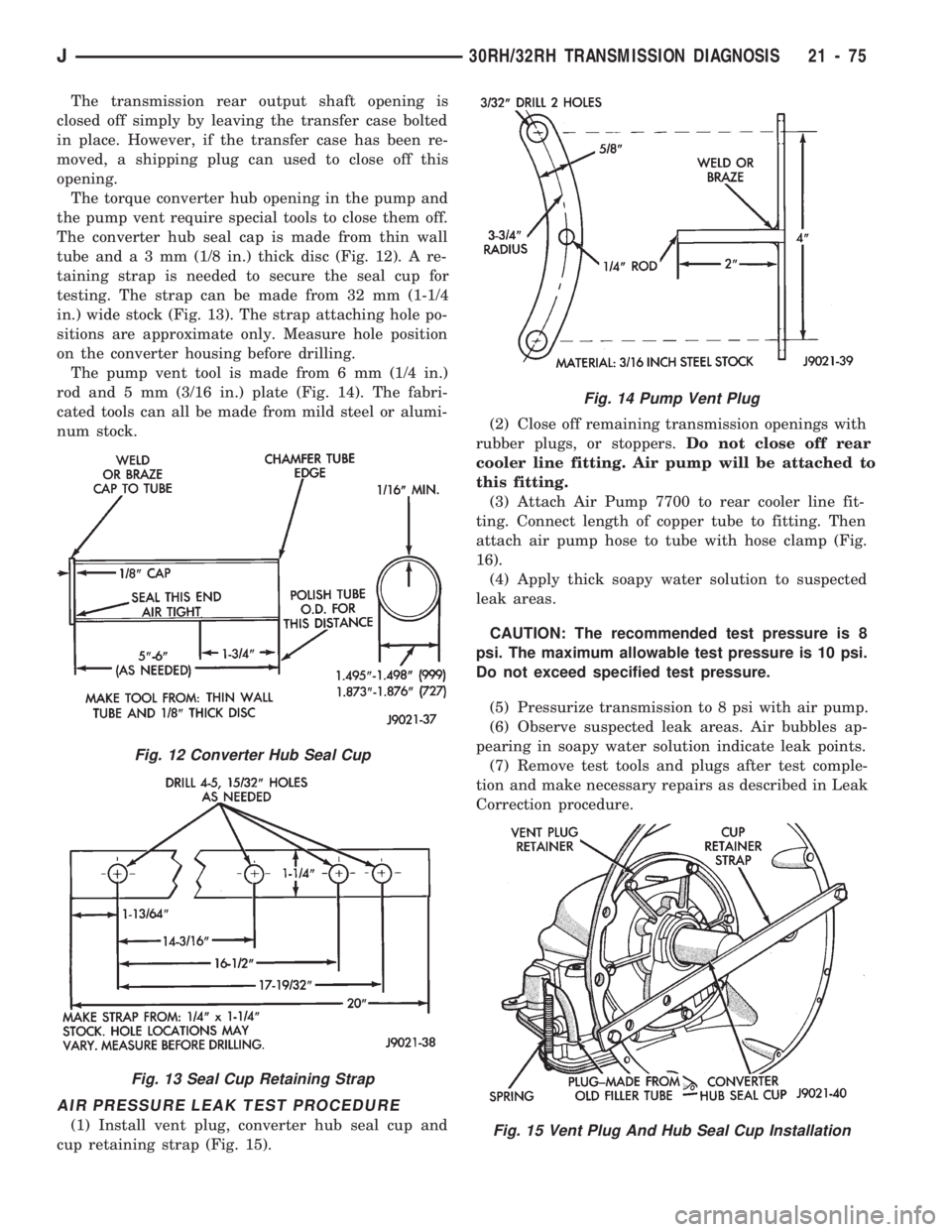
The converter hub seal cap is made from thin wall
tube anda3mm(1/8 in.) thick disc (Fig. 12). A re-
taining strap is needed to secure the seal cup for
testing. The strap can be made from 32 mm (1-1/4
in.) wide stock (Fig. 13). The strap attaching hole po-
sitions are approximate only. Measure hole position
on the converter housing before drilling.
The pump vent tool is made from 6 mm (1/4 in.)
rod and 5 mm (3/16 in.) plate (Fig. 14). The fabri-
cated tools can all be made from mild steel or alumi-
num stock.
AIR PRESSURE LEAK TEST PROCEDURE
(1) Install vent plug, converter hub seal cup and
cup retaining strap (Fig. 15).(2) Close off remaining transmission openings with
rubber plugs, or stoppers.Do not close off rear
cooler line fitting. Air pump will be attached to
this fitting.
(3) Attach Air Pump 7700 to rear cooler line fit-
ting. Connect length of copper tube to fitting. Then
attach air pump hose to tube with hose clamp (Fig.
16).
(4) Apply thick soapy water solution to suspected
leak areas.
CAUTION: The recommended test pressure is 8
psi. The maximum allowable test pressure is 10 psi.
Do not exceed specified test pressure.
(5) Pressurize transmission to 8 psi with air pump.
(6) Observe suspected leak areas. Air bubbles ap-
pearing in soapy water solution indicate leak points.
(7) Remove test tools and plugs after test comple-
tion and make necessary repairs as described in Leak
Correction procedure.
Fig. 12 Converter Hub Seal Cup
Fig. 13 Seal Cup Retaining Strap
Fig. 14 Pump Vent Plug
Fig. 15 Vent Plug And Hub Seal Cup Installation
J30RH/32RH TRANSMISSION DIAGNOSIS 21 - 75