1994 JEEP CHEROKEE ECU
[x] Cancel search: ECUPage 356 of 1784
²antenna connector
²blower motor resistors
²ground lead
²disconnect glove box light
²defroster cowl panel
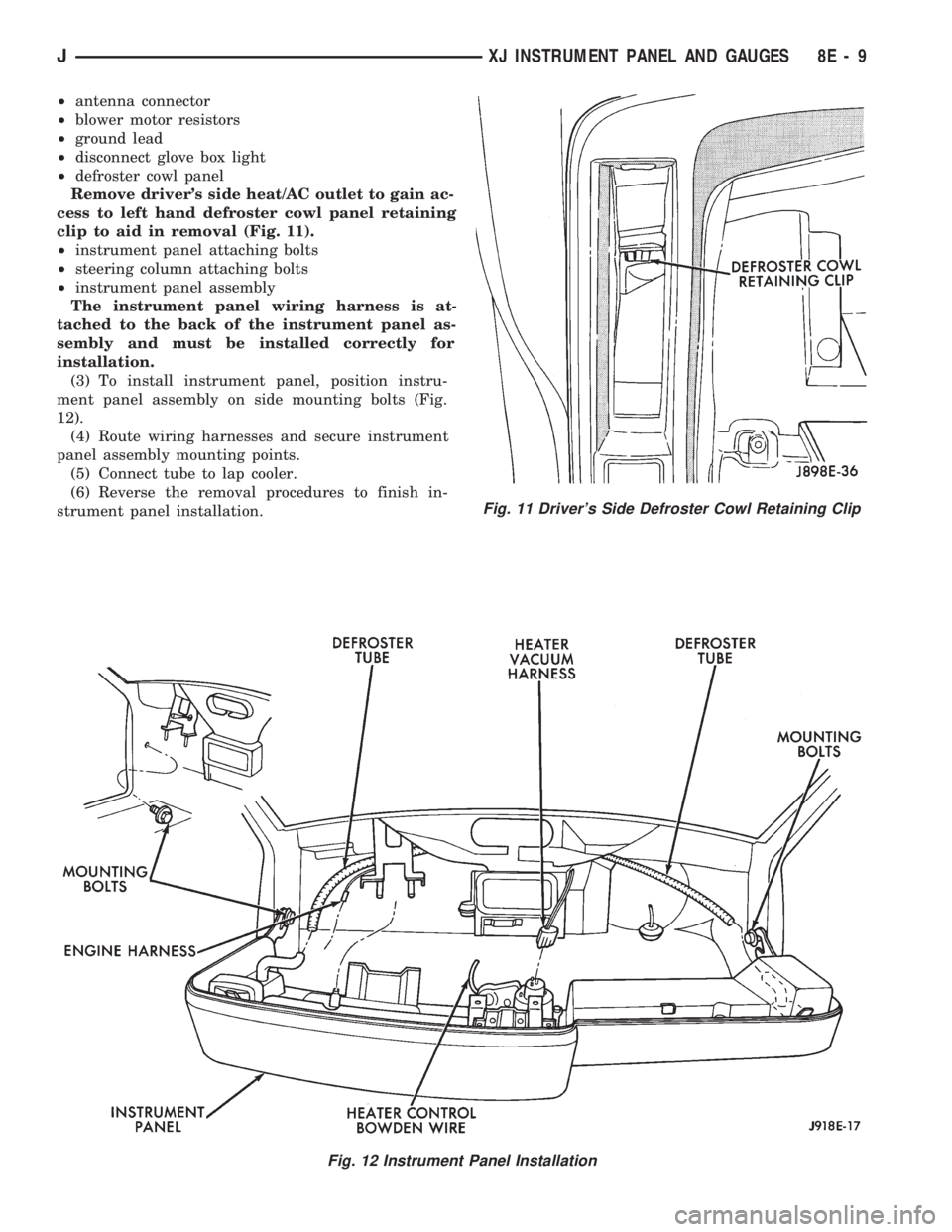
Remove driver's side heat/AC outlet to gain ac-
cess to left hand defroster cowl panel retaining
clip to aid in removal (Fig. 11).
²instrument panel attaching bolts
²steering column attaching bolts
²instrument panel assembly
The instrument panel wiring harness is at-
tached to the back of the instrument panel as-
sembly and must be installed correctly for
installation.
(3) To install instrument panel, position instru-
ment panel assembly on side mounting bolts (Fig.
12).
(4) Route wiring harnesses and secure instrument
panel assembly mounting points.
(5) Connect tube to lap cooler.
(6) Reverse the removal procedures to finish in-
strument panel installation.
Fig. 11 Driver's Side Defroster Cowl Retaining Clip
Fig. 12 Instrument Panel Installation
JXJ INSTRUMENT PANEL AND GAUGES 8E - 9
Page 383 of 1784
RADIO ANTENNA
INDEX
page page
Antenna Tests............................ 9
General Information........................ 8Replacement............................. 8
GENERAL INFORMATION
AM/FM radio model antennas must have a good
ground to eliminate static. The antenna mast is con-
nected to the inner wire of the coaxial cable and is
not grounded to any part of the vehicle. The coaxial
shield (the wire mesh) surrounding the center con-
ductor wire of the antenna lead-in cable is grounded
to the radio and the antenna base.
REPLACEMENT
XJ
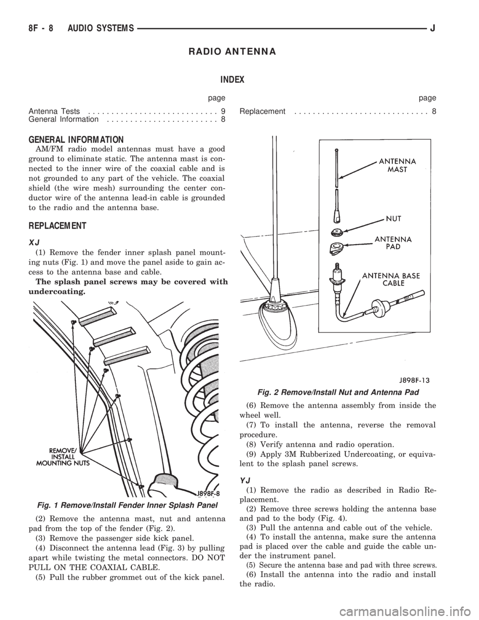
(1) Remove the fender inner splash panel mount-
ing nuts (Fig. 1) and move the panel aside to gain ac-
cess to the antenna base and cable.
The splash panel screws may be covered with
undercoating.
(2) Remove the antenna mast, nut and antenna
pad from the top of the fender (Fig. 2).
(3) Remove the passenger side kick panel.
(4) Disconnect the antenna lead (Fig. 3) by pulling
apart while twisting the metal connectors. DO NOT
PULL ON THE COAXIAL CABLE.
(5) Pull the rubber grommet out of the kick panel.(6) Remove the antenna assembly from inside the
wheel well.
(7) To install the antenna, reverse the removal
procedure.
(8) Verify antenna and radio operation.
(9) Apply 3M Rubberized Undercoating, or equiva-
lent to the splash panel screws.
YJ
(1) Remove the radio as described in Radio Re-
placement.
(2) Remove three screws holding the antenna base
and pad to the body (Fig. 4).
(3) Pull the antenna and cable out of the vehicle.
(4) To install the antenna, make sure the antenna
pad is placed over the cable and guide the cable un-
der the instrument panel.
(5) Secure the antenna base and pad with three screws.
(6) Install the antenna into the radio and install
the radio.
Fig. 1 Remove/Install Fender Inner Splash Panel
Fig. 2 Remove/Install Nut and Antenna Pad
8F - 8 AUDIO SYSTEMSJ
Page 394 of 1784
TEST PROCEDURES
INDEX
page page
Checking for Diagnostic Trouble Code......... 5
Electrical Tests at Powertrain Control Module.... 6
Electrical Tests at Servo.................... 5
Inoperative System........................ 5
Operational Check (Road Test)............... 7
Road Test............................... 5Speed Control Switch (Turn Signal Lever) Test . . . 7
Stop Lamp Speed Control Switch Test......... 7
Vacuum Supply Test....................... 7
Vehicle Speed Control System Electrical Tests . . . 5
Vehicle Speed Sensor Test.................. 5
ROAD TEST
Refer to Operational Check (Road Test) section to
verify reports of speed control system malfunction.
INOPERATIVE SYSTEM
Road test vehicle to verify reports of speed control
system malfunction. An inspection should be made
for loose electrical and vacuum connections at the
servo.
Check for correct installation of the vacuum check
valve in the hose from servo to vacuum source. The
word VAC on the valve must point toward the vac-
uum source.
Corrosion should be removed from electrical termi-
nals and a light coating of Mopar MultiPurpose
Grease, or equivalent, applied.
Inspection also should be made to verify that both
ends of the speed control cable are securely attached.
CHECKING FOR DIAGNOSTIC TROUBLE CODE
(1) When trying to verify a speed control system
electronic malfunction use a DRB scan tool to find
the cause (refer to Powertrain Diagnostic Procedures
manual).
If DRB is not available, the Diagnostic Trouble
Code (DTC) may be determined with the following
method:
(a) With key inserted in ignition switch, cycle
switch to ON position 3 times. On third cycle, leave
switch in ON position.
(b) After switch has been cycled 3 times, observe
Malfunction Indicator Lamp (CHECK ENGINE)
on instrument cluster. If a DTC is present, the code
will be displayed in a series of flashes representing
digits. Three flashes in rapid succession, a slight
pause, then 4 flashes in rapid succession would in-
dicate DTC 34.
(2) If a DTC 34 is observed, perform tests in the
sections Electrical Tests at Servo and Electrical Tests
at Powertrain Control Module.
If a DTC 15 is observed, perform test for a faulty
vehicle speed sensor.
(3) Correct any problems found when performing
these tests and recheck for DTC if changes were
made.
VEHICLE SPEED SENSOR TEST
For testing of the vehicle speed sensor and related
components, refer to Powertrain Diagnostic Proce-
dures manual.
VEHICLE SPEED CONTROL SYSTEM ELECTRICAL
TESTS
Vehicle speed control systems may be tested using
two different methods. One involves use of a DRB
scan tool. If this test method is desired, refer to Pow-
ertrain Diagnostic Procedures manual.
The other test method uses a voltmeter. The volt-
meter method is described in the following tests.
If any information is needed concerning wiring, re-
fer to Section 8W - Wiring Diagrams.
CAUTION: When test probing for voltage or conti-
nuity at electrical connectors, care must be taken
not to damage connector, terminals, or seals. If
these components are damaged, intermittent or
complete system failure may occur.
ELECTRICAL TESTS AT SERVO
(1) Turn ignition switch to the ON position. With
speed control switch in the ON position, setup a volt-
meter to read battery voltage and connect negative
lead to a good chassis ground.
(2) Disconnect 4-way connector going to servo
(Figs. 2 and 3). Blue wire with red tracer of main
harness 4-way connector should read approximately
battery voltage. If not, check for loose connections,
brake switch adjustment or, repair main harness as
necessary.
(3) Connect a jumper wire between male and fe-
male terminals of blue wire with red tracer. The
other 3 male terminals from servo should show bat-
tery voltage. If not, replace servo.
(4) Using an ohmmeter, connect one lead to a good
body ground. Touch other lead to black wire terminal
in 4-way connector of main harness. Meter should
show continuity. If not, repair ground circuit as nec-
essary.
JVEHICLE SPEED CONTROL SYSTEM 8H - 5
Page 430 of 1784
HEADLAMP BULB REPLACEMENT
REMOVAL
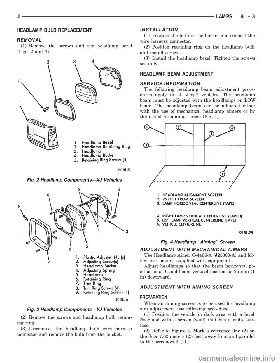
(1) Remove the screws and the headlamp bezel
(Figs. 2 and 3).
(2) Remove the screws and headlamp bulb retain-
ing ring.
(3) Disconnect the headlamp bulb wire harness
connector and remove the bulb from the bucket.
INSTALLATION
(1) Position the bulb in the bucket and connect the
wire harness connector.
(2) Position retaining ring on the headlamp bulb
and install screws.
(3) Install the headlamp bezel. Tighten the screws
securely.
HEADLAMP BEAM ADJUSTMENT
SERVICE INFORMATION
The following headlamp beam adjustment proce-
dures apply to all Jeeptvehicles. The headlamp
beam must be adjusted with the headlamps on LOW
beam. The headlamp beam can be adjusted either
with the use of mechanical headlamp aimers or by
the use of an aiming screen (Fig. 4).
ADJUSTMENT WITH MECHANICAL AIMERS
Use Headlamp Aimer C-4466-A (J25300-A) and fol-
low instructions supplied with equipment.
Adjust headlamps so that the beam horizontal po-
sition is at 0 and beam vertical position is 25 mm (1
in) downward.
ADJUSTMENT WITH AIMING SCREEN
PREPARATION
When an aiming screen is to be used for headlamp
aim adjustment, use following procedure.
(1) Position the vehicle in dark area with a level
floor and with a screen (wall) that has a white sur-
face.
(2) Refer to Figure 4. Mark a reference line (2) on
the floor 7.62 meters (25 feet) away from and parallel
to the screen/wall (1).
Fig. 2 Headlamp ComponentsÐXJ Vehicles
Fig. 3 Headlamp ComponentsÐYJ Vehicles
Fig. 4 Headlamp ``Aiming'' Screen
JLAMPS 8L - 3
Page 436 of 1784
(5) Install the outer screws in the headlamp bezel.
Tighten the screws.
(6) Position the side marker lamp lens/housing on
the headlamp bezel.
(7) Install side marker lamp lens/housing screws
and headlamp bezel (Fig. 19). Tighten the screws.
REMOVALÐYJ VEHICLES
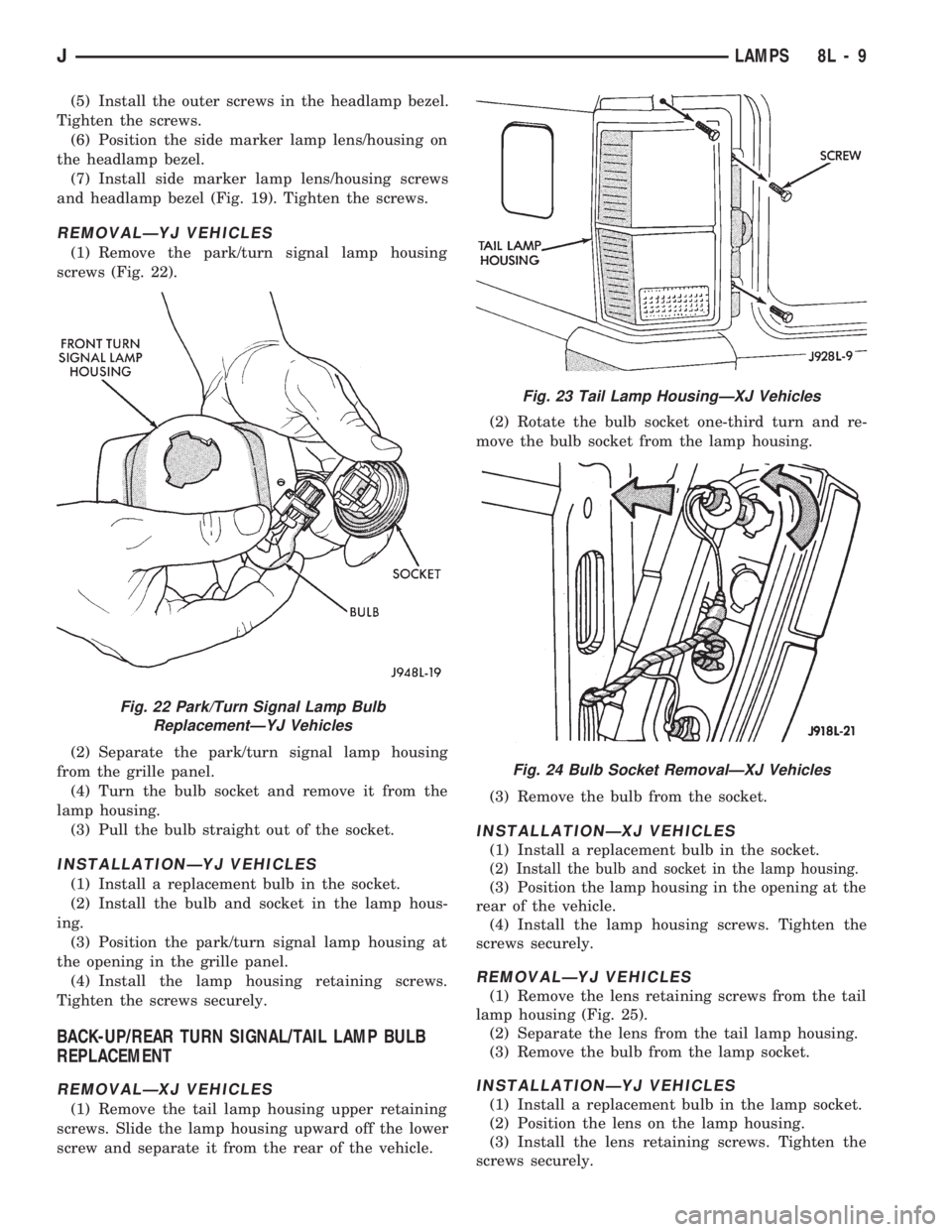
(1) Remove the park/turn signal lamp housing
screws (Fig. 22).
(2) Separate the park/turn signal lamp housing
from the grille panel.
(4) Turn the bulb socket and remove it from the
lamp housing.
(3) Pull the bulb straight out of the socket.
INSTALLATIONÐYJ VEHICLES
(1) Install a replacement bulb in the socket.
(2) Install the bulb and socket in the lamp hous-
ing.
(3) Position the park/turn signal lamp housing at
the opening in the grille panel.
(4) Install the lamp housing retaining screws.
Tighten the screws securely.
BACK-UP/REAR TURN SIGNAL/TAIL LAMP BULB
REPLACEMENT
REMOVALÐXJ VEHICLES
(1) Remove the tail lamp housing upper retaining
screws. Slide the lamp housing upward off the lower
screw and separate it from the rear of the vehicle.(2) Rotate the bulb socket one-third turn and re-
move the bulb socket from the lamp housing.
(3) Remove the bulb from the socket.
INSTALLATIONÐXJ VEHICLES
(1) Install a replacement bulb in the socket.
(2) Install the bulb and socket in the lamp housing.
(3) Position the lamp housing in the opening at the
rear of the vehicle.
(4) Install the lamp housing screws. Tighten the
screws securely.
REMOVALÐYJ VEHICLES
(1) Remove the lens retaining screws from the tail
lamp housing (Fig. 25).
(2) Separate the lens from the tail lamp housing.
(3) Remove the bulb from the lamp socket.
INSTALLATIONÐYJ VEHICLES
(1) Install a replacement bulb in the lamp socket.
(2) Position the lens on the lamp housing.
(3) Install the lens retaining screws. Tighten the
screws securely.
Fig. 22 Park/Turn Signal Lamp Bulb
ReplacementÐYJ Vehicles
Fig. 23 Tail Lamp HousingÐXJ Vehicles
Fig. 24 Bulb Socket RemovalÐXJ Vehicles
JLAMPS 8L - 9
Page 437 of 1784
LICENSE PLATE LAMP
REMOVALÐXJ VEHICLES
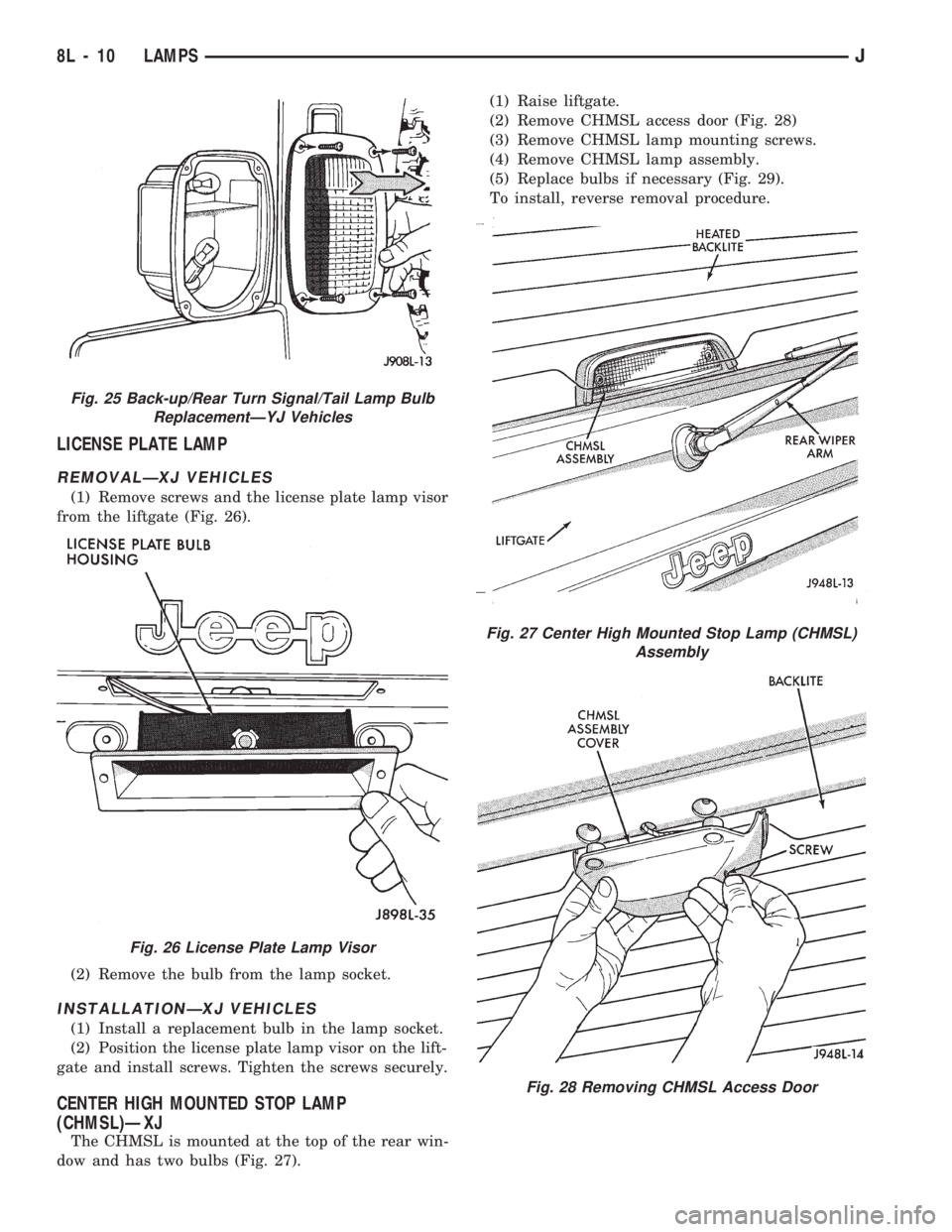
(1) Remove screws and the license plate lamp visor
from the liftgate (Fig. 26).
(2) Remove the bulb from the lamp socket.
INSTALLATIONÐXJ VEHICLES
(1) Install a replacement bulb in the lamp socket.
(2) Position the license plate lamp visor on the lift-
gate and install screws. Tighten the screws securely.
CENTER HIGH MOUNTED STOP LAMP
(CHMSL)ÐXJ
The CHMSL is mounted at the top of the rear win-
dow and has two bulbs (Fig. 27).(1) Raise liftgate.
(2) Remove CHMSL access door (Fig. 28)
(3) Remove CHMSL lamp mounting screws.
(4) Remove CHMSL lamp assembly.
(5) Replace bulbs if necessary (Fig. 29).
To install, reverse removal procedure.
Fig. 25 Back-up/Rear Turn Signal/Tail Lamp Bulb
ReplacementÐYJ Vehicles
Fig. 26 License Plate Lamp Visor
Fig. 27 Center High Mounted Stop Lamp (CHMSL)
Assembly
Fig. 28 Removing CHMSL Access Door
8L - 10 LAMPSJ
Page 441 of 1784
(3) For XJ vehicles, position the bezel and the lens
on the lamp housing. Install the screws that attach
the bezel and lens to the lamp housing. Tighten the
screws securely.
(4) For YJ vehicles, position the stone shield and
reflector on the lamp housing. Install the screws that
attach the stone shield and the reflector to the lamp
housing. Tighten the screws securely.
FOG LAMP SWITCH REPLACEMENT
REMOVALÐXJ VEHICLES
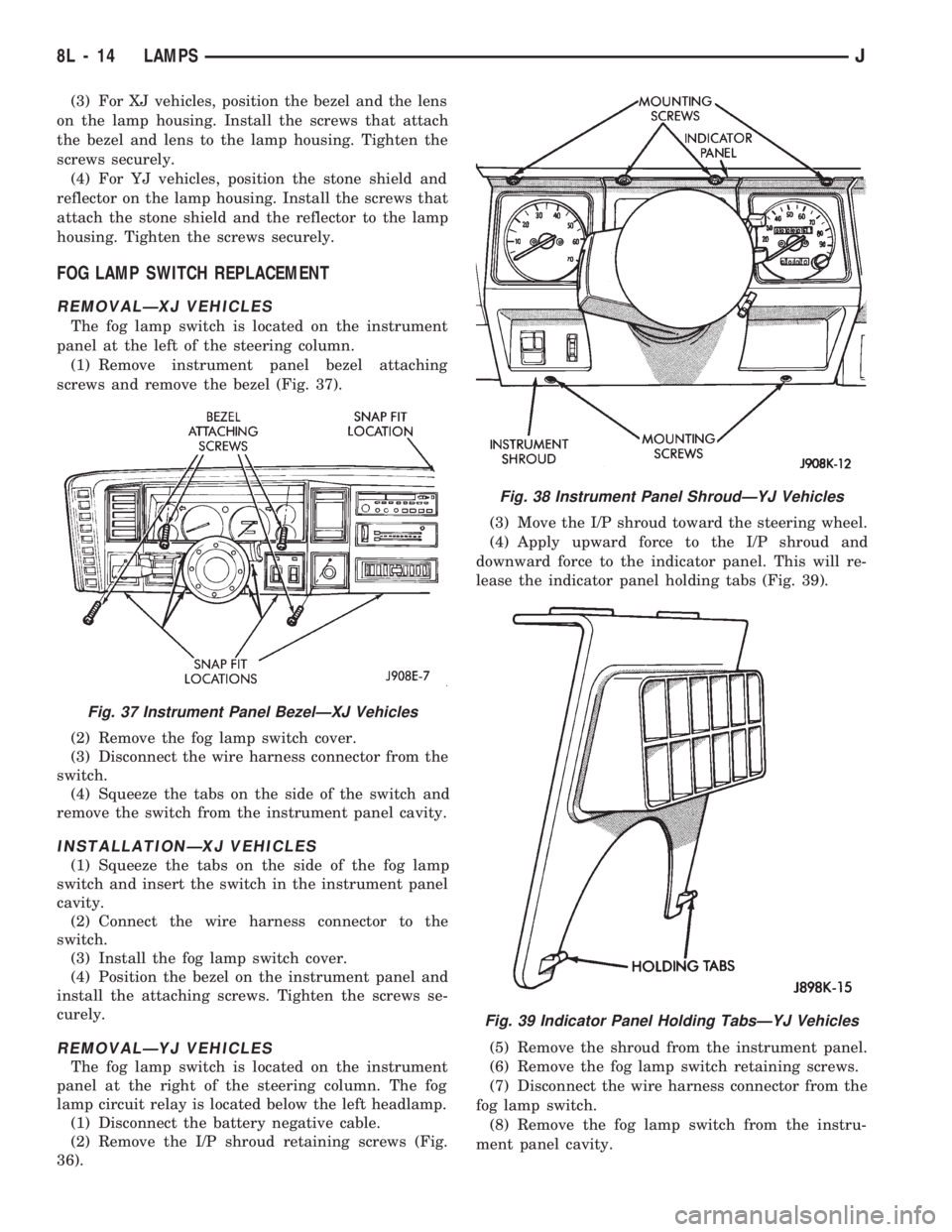
The fog lamp switch is located on the instrument
panel at the left of the steering column.
(1) Remove instrument panel bezel attaching
screws and remove the bezel (Fig. 37).
(2) Remove the fog lamp switch cover.
(3) Disconnect the wire harness connector from the
switch.
(4) Squeeze the tabs on the side of the switch and
remove the switch from the instrument panel cavity.
INSTALLATIONÐXJ VEHICLES
(1) Squeeze the tabs on the side of the fog lamp
switch and insert the switch in the instrument panel
cavity.
(2) Connect the wire harness connector to the
switch.
(3) Install the fog lamp switch cover.
(4) Position the bezel on the instrument panel and
install the attaching screws. Tighten the screws se-
curely.
REMOVALÐYJ VEHICLES
The fog lamp switch is located on the instrument
panel at the right of the steering column. The fog
lamp circuit relay is located below the left headlamp.
(1) Disconnect the battery negative cable.
(2) Remove the I/P shroud retaining screws (Fig.
36).(3) Move the I/P shroud toward the steering wheel.
(4) Apply upward force to the I/P shroud and
downward force to the indicator panel. This will re-
lease the indicator panel holding tabs (Fig. 39).
(5) Remove the shroud from the instrument panel.
(6) Remove the fog lamp switch retaining screws.
(7) Disconnect the wire harness connector from the
fog lamp switch.
(8) Remove the fog lamp switch from the instru-
ment panel cavity.
Fig. 37 Instrument Panel BezelÐXJ Vehicles
Fig. 38 Instrument Panel ShroudÐYJ Vehicles
Fig. 39 Indicator Panel Holding TabsÐYJ Vehicles
8L - 14 LAMPSJ
Page 442 of 1784
INSTALLATIONÐYJ VEHICLES
(1) Position the fog lamp switch in the instrument
panel cavity and connect the wire harness connector
to the switch.
(2) Install the fog lamp switch retaining screws.
Tighten the screws securely.
(3) Position the I/P shroud under the steering col-
umn.
(4) Slide the indicator panel holding tabs into the
shroud notches.
(5) Place the assembled I/P shroud over the indica-
tor lamp foam gasket.
The foam gasket located on the back side of
the indicator panel overlay is fragile. If it is ei-
ther torn or distorted, replace it.
(6) Install and tighten the indicator panel retain-
ing screws.
(7) Install the remaining shroud screws. Tighten
the screws securely.
(8) Connect the battery negative cable.
FOG LAMP REPLACEMENT
REMOVALÐXJ VEHICLES
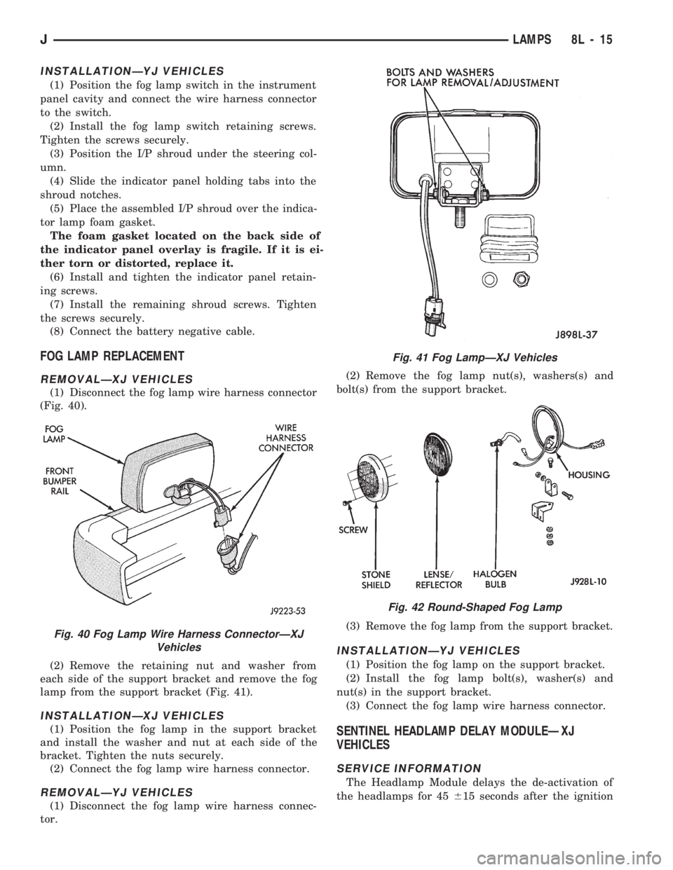
(1) Disconnect the fog lamp wire harness connector
(Fig. 40).
(2) Remove the retaining nut and washer from
each side of the support bracket and remove the fog
lamp from the support bracket (Fig. 41).
INSTALLATIONÐXJ VEHICLES
(1) Position the fog lamp in the support bracket
and install the washer and nut at each side of the
bracket. Tighten the nuts securely.
(2) Connect the fog lamp wire harness connector.
REMOVALÐYJ VEHICLES
(1) Disconnect the fog lamp wire harness connec-
tor.(2) Remove the fog lamp nut(s), washers(s) and
bolt(s) from the support bracket.
(3) Remove the fog lamp from the support bracket.
INSTALLATIONÐYJ VEHICLES
(1) Position the fog lamp on the support bracket.
(2) Install the fog lamp bolt(s), washer(s) and
nut(s) in the support bracket.
(3) Connect the fog lamp wire harness connector.
SENTINEL HEADLAMP DELAY MODULEÐXJ
VEHICLES
SERVICE INFORMATION
The Headlamp Module delays the de-activation of
the headlamps for 45615 seconds after the ignition
Fig. 40 Fog Lamp Wire Harness ConnectorÐXJ
Vehicles
Fig. 41 Fog LampÐXJ Vehicles
Fig. 42 Round-Shaped Fog Lamp
JLAMPS 8L - 15