1994 JEEP CHEROKEE ECU
[x] Cancel search: ECUPage 444 of 1784
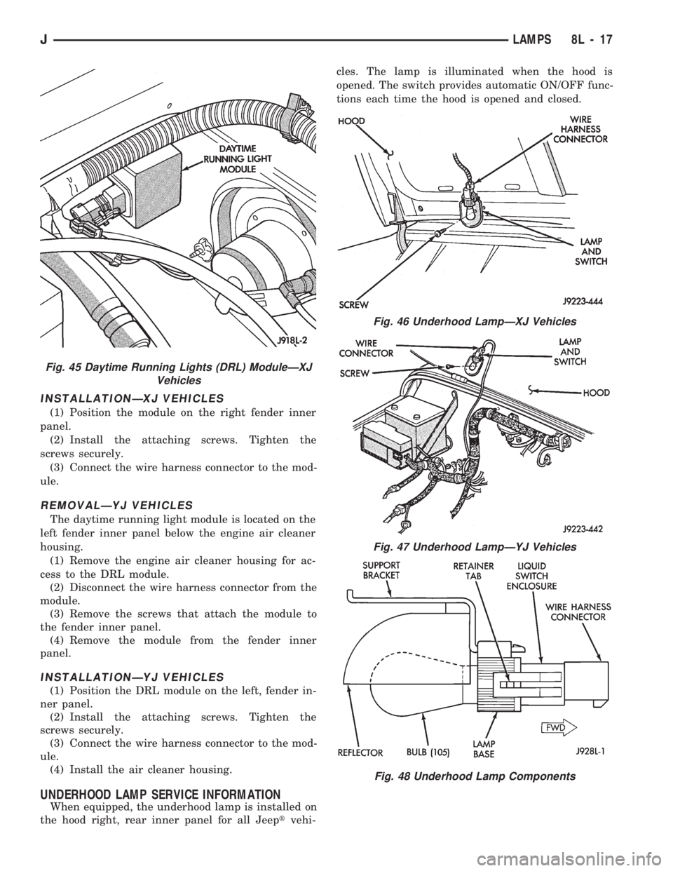
INSTALLATIONÐXJ VEHICLES
(1) Position the module on the right fender inner
panel.
(2) Install the attaching screws. Tighten the
screws securely.
(3) Connect the wire harness connector to the mod-
ule.
REMOVALÐYJ VEHICLES
The daytime running light module is located on the
left fender inner panel below the engine air cleaner
housing.
(1) Remove the engine air cleaner housing for ac-
cess to the DRL module.
(2) Disconnect the wire harness connector from the
module.
(3) Remove the screws that attach the module to
the fender inner panel.
(4) Remove the module from the fender inner
panel.
INSTALLATIONÐYJ VEHICLES
(1) Position the DRL module on the left, fender in-
ner panel.
(2) Install the attaching screws. Tighten the
screws securely.
(3) Connect the wire harness connector to the mod-
ule.
(4) Install the air cleaner housing.
UNDERHOOD LAMP SERVICE INFORMATION
When equipped, the underhood lamp is installed on
the hood right, rear inner panel for all Jeeptvehi-cles. The lamp is illuminated when the hood is
opened. The switch provides automatic ON/OFF func-
tions each time the hood is opened and closed.
Fig. 45 Daytime Running Lights (DRL) ModuleÐXJ
Vehicles
Fig. 46 Underhood LampÐXJ Vehicles
Fig. 47 Underhood LampÐYJ Vehicles
Fig. 48 Underhood Lamp Components
JLAMPS 8L - 17
Page 445 of 1784
UNDERHOOD LAMP BULB REPLACEMENT
REMOVALÐALL VEHICLES
(1) Disconnect the wire harness connector from the
underhood lamp.
(2) Rotate the bulb counter-clockwise and remove
it from the lamp base socket.
INSTALLATIONÐALL VEHICLES
(1) Insert a replacement bulb in the lamp base
socket and rotate it clockwise.
(2) Connect the wire harness connector to the
lamp.
UNDERHOOD LAMP REPLACEMENT
REMOVALÐALL VEHICLES
(1) Disconnect the wire harness connector from the
lamp.(2) Rotate the bulb counter-clockwise and remove
it from the lamp base socket.
(3) Remove the screw that attaches the lamp re-
flector and support bracket to the hood inner panel.
(4) Remove the lamp from the hood inner panel.
INSTALLATIONÐALL VEHICLES
(1) Position the underhood lamp on the hood inner
panel.
(2) Install the attaching screw through the lamp
and into the hood panel. Tighten the screw securely.
(3) Insert a replacement bulb in the lamp base
socket and rotate it clockwise.
(4) Connect the wire harness connector to the
lamp.
8L - 18 LAMPSJ
Page 446 of 1784
INTERIOR LAMPS
INDEX
page page
Dome Lamp Replacement.................. 20
Dome/Courtesy Lamp Service Information...... 19
Dome/Courtesy Lamp Trouble Diagnosis....... 19
Hardtop Dome/Cargo Lamp Bulb ReplacementÐYJ
Vehicles.............................. 20Illuminated Entry System Service Information . . . 20
Illuminated Entry System Trouble Diagnosis.... 21
Lighted Vanity Mirror...................... 19
Lighted Vanity Mirror Trouble Diagnosis....... 19
Overhead ConsoleÐXJ Vehicles............. 20
DOME/COURTESY LAMP SERVICE INFORMATION
XJ VEHICLES
Voltage is applied at all times via the dome lamp
fuse to each of the interior lamp bulbs. The interior
lamp bulbs illuminate when they are connected to
body ground via the switch:
²headlamp switch,
²glove box switch,
²door pillar switch, and
²liftgate switch (if the cargo lamp is ON.)
If equipped with Security Alarm Module, refer to
Group 8QÐVehicle Theft Security System.
YJ VEHICLES
The dome/cargo and courtesy lamps are controlled
via ON/OFF switches. The ON/OFF switches are in
the lamp ground circuits. Voltage via the dome/cour-
tesy lamp fuse is applied directly to the lamp bulbs.
When either door is opened, the door pillar switch
contacts close and provide a direct path to vehicle
body ground.
The cargo/cargo and courtesy lamps can also be
turned on via the interior lamp illumination rheo-
stat.
DOME/COURTESY LAMP TROUBLE DIAGNOSIS
ALL LAMPS INOPERATIVE
(1) Rotate the headlamp switch rheostat clockwise.
The lamps should light. If not OK, remove, inspect
and test the dome lamp fuse. Replace if bad.
(2) If the fuse is OK, repair the open circuit in the
wire harness to vehicle body ground.
ONE LAMP INOPERATIVE
(1) Measure the resistance across the bulb holder
terminals. The ohmmeter should indicate zero ohms.
If not, replace the bulb.
(2) Measure the voltage between the voltage side
of the bulb holder and vehicle body ground. The volt-
meter should indicate battery voltage. If not, repair
the open circuit in the wire harness to the splice.
LAMPS INOPERATIVE WITH ONE OR MORE
DOORS OPENED
(1) Remove the inoperative switch from the door
pillar and connect the switch wire directly to ground.
The lamp should light.
(2) If not, check for an open circuit in black
(ground) wire. Repair as necessary. If lamps still do
not light, replace the switch.
LIGHTED VANITY MIRROR
SERVICE INFORMATIONÐXJ VEHICLES
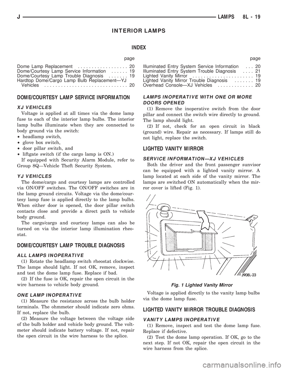
Both the driver and the front passenger sunvisor
can be equipped with a lighted vanity mirror. A
lamp located at each side of the vanity mirror. The
lamps are switched ON automatically when the mir-
ror cover is lifted (Fig. 1).
Voltage is applied directly to the vanity lamp bulbs
via the dome lamp fuse.
LIGHTED VANITY MIRROR TROUBLE DIAGNOSIS
VANITY LAMPS INOPERATIVE
(1) Remove, inspect and test the dome lamp fuse.
Replace if defective.
(2) Test the dome lamp operation. If OK, go to the
next step. If not OK, repair the open circuit in the
wire harness from the splice.
Fig. 1 Lighted Vanity Mirror
JLAMPS 8L - 19
Page 468 of 1784
POWER SEATS
CONTENTS
page page
DIAGNOSIS............................. 1
GENERAL.............................. 1POWER SEAT MOTOR REPLACEMENT....... 2
SWITCH TESTING....................... 2
GENERAL
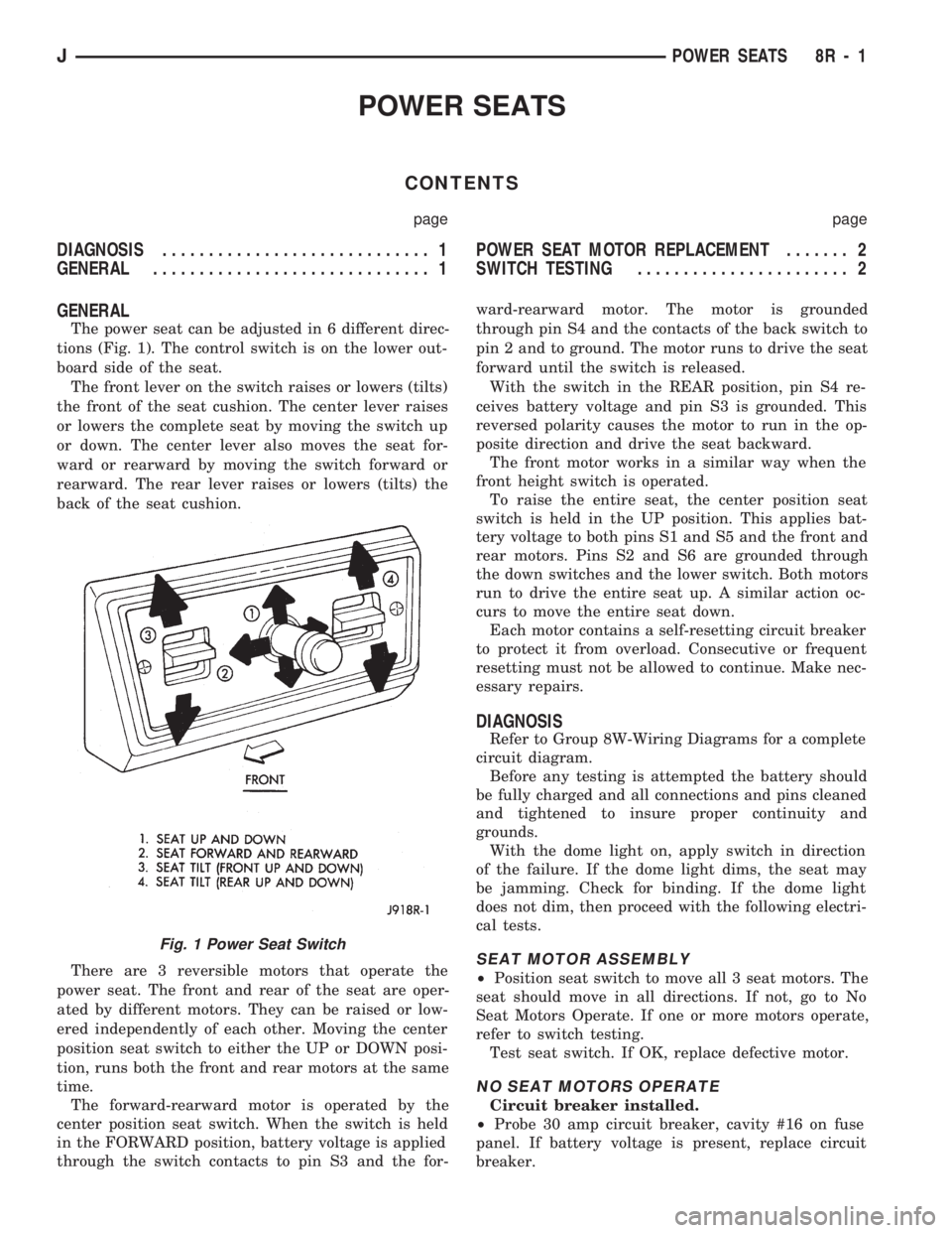
The power seat can be adjusted in 6 different direc-
tions (Fig. 1). The control switch is on the lower out-
board side of the seat.
The front lever on the switch raises or lowers (tilts)
the front of the seat cushion. The center lever raises
or lowers the complete seat by moving the switch up
or down. The center lever also moves the seat for-
ward or rearward by moving the switch forward or
rearward. The rear lever raises or lowers (tilts) the
back of the seat cushion.
There are 3 reversible motors that operate the
power seat. The front and rear of the seat are oper-
ated by different motors. They can be raised or low-
ered independently of each other. Moving the center
position seat switch to either the UP or DOWN posi-
tion, runs both the front and rear motors at the same
time.
The forward-rearward motor is operated by the
center position seat switch. When the switch is held
in the FORWARD position, battery voltage is applied
through the switch contacts to pin S3 and the for-ward-rearward motor. The motor is grounded
through pin S4 and the contacts of the back switch to
pin 2 and to ground. The motor runs to drive the seat
forward until the switch is released.
With the switch in the REAR position, pin S4 re-
ceives battery voltage and pin S3 is grounded. This
reversed polarity causes the motor to run in the op-
posite direction and drive the seat backward.
The front motor works in a similar way when the
front height switch is operated.
To raise the entire seat, the center position seat
switch is held in the UP position. This applies bat-
tery voltage to both pins S1 and S5 and the front and
rear motors. Pins S2 and S6 are grounded through
the down switches and the lower switch. Both motors
run to drive the entire seat up. A similar action oc-
curs to move the entire seat down.
Each motor contains a self-resetting circuit breaker
to protect it from overload. Consecutive or frequent
resetting must not be allowed to continue. Make nec-
essary repairs.
DIAGNOSIS
Refer to Group 8W-Wiring Diagrams for a complete
circuit diagram.
Before any testing is attempted the battery should
be fully charged and all connections and pins cleaned
and tightened to insure proper continuity and
grounds.
With the dome light on, apply switch in direction
of the failure. If the dome light dims, the seat may
be jamming. Check for binding. If the dome light
does not dim, then proceed with the following electri-
cal tests.
SEAT MOTOR ASSEMBLY
²Position seat switch to move all 3 seat motors. The
seat should move in all directions. If not, go to No
Seat Motors Operate. If one or more motors operate,
refer to switch testing.
Test seat switch. If OK, replace defective motor.
NO SEAT MOTORS OPERATE
Circuit breaker installed.
²Probe 30 amp circuit breaker, cavity #16 on fuse
panel. If battery voltage is present, replace circuit
breaker.
Fig. 1 Power Seat Switch
JPOWER SEATS 8R - 1
Page 472 of 1784
POWER WINDOWS
CONTENTS
page page
DESCRIPTION........................... 1
DIAGNOSIS (Figs. 1 and 2)............... 1SWITCH TESTING....................... 5
WINDOW REGULATOR REPLACEMENT...... 9
DESCRIPTION
All XJ vehicles, equipped with power windows,
have a cable driven window regulator system. A per-
manent magnet motor moves each power window.
Each motor raises or lowers the glass when voltage
is supplied to the motor. The direction the motor
turns depends on the polarity of the supply voltage.
The control switches control the supply voltage polar-
ity.
With the ignition switch in the ON position voltage
from the 60 amp fuse in the Power Distribution Cen-
ter is applied through the power window circuit
breaker. Power then goes to the master switch termi-
nal BY and to the passenger's window switches.
When the driver's window switch is moved UP, the
contacts close a current path to:
²terminal DV
²driver's side front window motor
²terminal CV
²the DOWN contact of the driver's side front win-
dow to ground.
The motor then moves the glass up.
Current flows in a similar way when the UP con-
tact in one of the passenger's window switches is
closed. Current flow through the passenger's window
motors must go through the driver's and the passen-
ger's window switches before it reaches ground.
Each motor is protected by a built-in circuit
breaker. If a window switch is held on too long with
the window obstructed or after the window is fully
up or down, the circuit breaker opens the circuit. The
circuit breaker resets automatically as it cools. Do
not allow frequent or consecutive resetting of the cir-
cuit breaker to continue.
DIAGNOSIS (Figs. 1 and 2)
For information concerning wiring or connectors,
refer to Group 8W - Wiring Diagrams.
NO WINDOWS OPERATE
²Measure voltage at power window feed connector
at fuse panel. Meter should read battery voltage. If
not, replace 60 amp fuse in Power Distribution Cen-
ter.
²Turn ignition switch to OFF and measure resis-
tance from side of cigar lighter socket to ground.
Meter should read zero ohms. If not, repair open to
ground.
²Remove master door lock/power window switch as-
sembly mounting screws. Measure resistance at BLK
wire (terminal DX) at driver's side switch. Meter
should read zero ohms. If not, repair open to ground
splice of instrument panel harness.
²Turn ignition switch to ON and measure voltage
at terminal BY at driver's side switch. Meter should
read battery voltage. If not, repair open to circuit
breaker.
²Operate window switch. If the windows move up
and down go to Switch Testing.
²Perform Switch Test Driver's Door. If switch
passes test, replace defective motors.
ONE WINDOW OPERATES
Remove door panel of inoperative window,
probe harness side of unplugged motor connec-
tor.
²Measure voltage at terminal A of connector, hold-
ing switch in the DOWN position. Meter should read
battery voltage. If not, repair open back to master
switch. If additional switch is in circuit (not driver's
side motor), refer to Switch Testing.
²Measure resistance at terminal B of connector,
holding switch in the DOWN position. Meter should
read zero ohms. Caution, maintain DOWN position
while meter lead is attached. If not, repair open back
to master switch. If additional switch is in circuit
(not driver's side motor), refer to Switch Testing. If
both tests are OK, replace regulator.
JPOWER WINDOWS 8S - 1
Page 497 of 1784
FUSIBLE LINK REPLACEMENT
CAUTION: Do not replace blown fusible links with a
standard wire. Only use fusible type wire with hypa-
lon insulation or damage to the electrical system
could occur. Also make sure correct gauge of wir-
ing is used. Refer to the wiring diagrams for proper
gauge and color.
When a fusible link blows it is important to find
out what the problem is. They are placed in the elec-
trical system for protection against shorts to ground.
This can be caused by a component failure or various
wiring failures.Do not just replace the fusible
link to correct the problem.
When diagnosing a faulty fusible link it is impor-
tant to check the wire carefully. In some instances
the link may be blown and it will not show through
the insulation, the wire should be checked over its
entire length for internal breaks.
(1) Disconnect battery negative cable.
(2) Cut out the blown portion of the fusible link.
(3) Strip 1 inch of insulation from each end of the
existing fusible link.
(4) Place a piece of heat shrink tubing over one
side of the fusible link. Make sure the tubing will be
long enough to cover and seal the entire repair area.
(5) Cut a replacement piece of fusible link approx-
imately two inches longer than the piece removed.
(6) Remove one inch of insulation from each end of
the replacement fusible link.
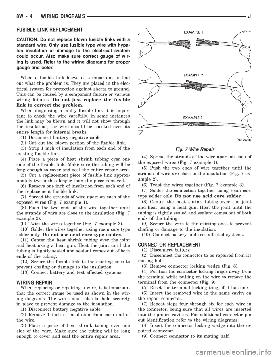
(7) Spread the strands of wire apart on each of the
exposed wires (Fig. 7 example 1).
(8) Push the two ends of the wire together until
the strands of wire are close to the insulation (Fig. 7
example 2).
(9) Twist the wires together (Fig. 7 example 3).
(10) Solder the wires together using rosin core type
solder only.Do not use acid core type solder.
(11) Center the heat shrink tubing over the joint
and heat using a heat gun. Heat the joint until the
tubing is tightly sealed and sealant comes out of both
ends of the tubing.
(12) Secure the fusible link to the existing ones to
prevent chafing or damage to the insulation.
(13) Connect battery and test affected systems.
WIRING REPAIR
When replacing or repairing a wire, it is important
that the correct gauge be used as shown in the wir-
ing diagrams. The wires must also be held securely
in place to prevent damage to the insulation.
(1) Disconnect battery negative cable.
(2) Remove 1 inch of insulation from each end of
the wire.
(3) Place a piece of heat shrink tubing over one
side of the wire. Make sure the tubing will be long
enough to cover and seal the entire repair area.(4) Spread the strands of the wire apart on each of
the exposed wires (Fig. 7 example 1).
(5) Push the two ends of wire together until the
strands of wire are close to the insulation (Fig. 7 ex-
ample 2).
(6) Twist the wires together (Fig. 7 example 3).
(7) Solder the connection together using rosin core
type solder only.Do not use acid core solder.
(8) Center the heat shrink tubing over the joint
and heat using a heat gun. Heat the joint until the
tubing is tightly sealed and sealant comes out of both
ends of the tubing.
(9) Secure the wire to the existing ones to prevent
chafing or damage to the insulation.
(10) Connect battery and test affected systems.
CONNECTOR REPLACEMENT
(1) Disconnect battery.
(2) Disconnect the connector to be repaired from its
mating half.
(3) Remove connector locking wedge (Fig. 8).
(4) Position the connector locking finger away from
the terminal while pulling on the wire to remove the
terminal from the connector (Fig. 9).
(5) Reset the terminal locking tang, if it has one.
(6) Insert the removed wire in the same cavity on
the repair connector.
(7) Repeat steps four through six for each wire in
the connector, being sure that all wires are inserted
into the proper cavities. For additional connector pin
out identification refer to the wiring diagrams.
(8) Insert the connector locking wedge into the re-
paired connector.
(9) Connect connector to its mating half.
Fig. 7 Wire Repair
8W - 4 WIRING DIAGRAMSJ
Page 846 of 1784
ENGINE DIAGNOSIS
Engine diagnosis is helpful in determining the
causes of malfunctions not detected and remedied by
routine tune-ups.
These malfunctions may be classified as either per-
formance (e.g., engine idles rough and stalls) or me-
chanical (e.g., a strange noise).
Refer to the Service DiagnosisÐPerformance chart
and the Service DiagnosisÐMechanical chart for pos-
sible causes and corrections of malfunctions. Refer to
Group 14, Fuel System for the fuel system diagnosis.
Additional tests and diagnostic procedures may be
necessary for specific engine malfunctions that can
not be isolated with the Service Diagnosis charts. In-
formation concerning additional tests and diagnosis
is provided within the following diagnosis:
²Cylinder Compression Pressure Test.
²Cylinder Combustion Pressure Leakage Test.
²Engine Cylinder Head Gasket Failure Diagnosis.
²Intake Manifold Leakage Diagnosis.
INTAKE MANIFOLD LEAKAGE DIAGNOSIS
An intake manifold air leak is characterized by
lower than normal manifold vacuum. Also, one or
more cylinders may not be functioning.
WARNING: USE EXTREME CAUTION WHEN THE
ENGINE IS OPERATING. DO NOT STAND IN A DI-
RECT LINE WITH THE FAN. DO NOT PUT YOUR
HANDS NEAR THE PULLEYS, BELTS OR THE FAN.
DO NOT WEAR LOOSE CLOTHING.
METHOD 1
(1) Start the engine.
(2) Open the acetylene valve of an oxyacetylene
torch. DO NOT ignite.
(3) Pass the torch tip over the exposed gasket area
(EDGE) between the manifold and the engine cylin-
der head.
(4) If the engine speed increases, the manifold has
an air leak.
METHOD 2
(1) Start the engine.
(2) Apply engine oil to the exposed gasket area
(EDGE) between the manifold and the engine cylin-
der head.
(3) If oil is forced into the manifold and if smoke is
visible from the exhaust tailpipe, the manifold has
an air leak.
CYLINDER COMPRESSION PRESSURE TEST
The results of a cylinder compression pressure test
can be utilized to diagnose several engine malfunc-
tions.
Ensure the battery is completely charged and the
engine starter motor is in good operating condition.Otherwise the indicated compression pressures may
not be valid for diagnosis purposes.
(1) Clean the spark plug recesses with compressed
air.
(2) Remove the spark plugs.
(3) Secure the throttle in the wide-open position.
(4) Disconnect the ignition coil.
(5) Insert a compression pressure gauge and rotate
the engine with the engine starter motor for three
revolutions.
(6) Record the compression pressure on the 3rd
revolution. Continue the test for the remaining cyl-
inders.
Refer to Engine Specifications for the correct en-
gine compression pressures.
ENGINE CYLINDER HEAD GASKET FAILURE
DIAGNOSIS
A leaking engine cylinder head gasket usually re-
sults in loss of power, loss of coolant and engine mis-
firing.
An engine cylinder head gasket leak can be located
between adjacent cylinders or between a cylinder and
the adjacent water jacket.
²An engine cylinder head gasket leaking between
adjacent cylinders is indicated by a loss of power
and/or engine misfire.
²An engine cylinder head gasket leaking between a
cylinder and an adjacent water jacket is indicated by
coolant foaming or overheating and loss of coolant.
CYLINDER-TO-CYLINDER LEAKAGE TEST
To determine if an engine cylinder head gasket is
leaking between adjacent cylinders; follow the proce-
dures outlined in Cylinder Compression Pressure
Test. An engine cylinder head gasket leaking be-
tween adjacent cylinders will result in approximately
a 50-70% reduction in compression pressure.
CYLINDER-TO-WATER JACKET LEAKAGE
TEST
WARNING: USE EXTREME CAUTION WHEN THE
ENGINE IS OPERATING. DO NOT STAND IN A DI-
RECT LINE WITH THE FAN. DO NOT PUT YOUR
HANDS NEAR THE PULLEYS, BELTS OR THE FAN.
DO NOT WEAR LOOSE CLOTHING.
Remove the radiator cap.
Start the engine and allow it to warm up until the
engine thermostat opens.
If a large combustion/compression pressure leak ex-
ists, bubbles will be visible in the coolant.
If bubbles are not visible, install a radiator pres-
sure tester and pressurize the coolant system.
JENGINES 9 - 5
Page 859 of 1784

(14) Install the remaining flywheel housing bolts.
Tighten the bolts to 38 Nzm (28 ft. lbs.) torque.
(15) Install the starter motor and connect the ca-
ble. Tighten the bolts to 45 Nzm (33 ft. lbs.) torque.
(16) Install the oil filter.
(17) Lower the vehicle.
(18) Connect the coolant hoses and tighten the
clamps.
(19) If equipped with power steering:
(a) Remove the protective caps
(b) Connect the hoses to the fittings at the steer-
ing gear. Tighten the nut to 52 Nzm (38 ft. lbs.)
torque.
(c) Fill the pump reservoir with fluid.
(20) Remove the pulley-to-water pump flange
alignment capscrew and install the fan and spacer or
Tempatrol fan assembly.
(21) Tighten the serpentine drive belt according to
the specifications listed in Group 7, Cooling System.
(22) Install the fan shroud and radiator.
(23) Connect the radiator hoses.
(24) Connect the heater hoses.
(25) Connect the throttle valve rod and retainer.
(26) Connect the throttle cable and install the rod.
(27) Install the throttle valve rod spring.
(28) Connect the speed control cable, if equipped.
(29) Connect the oxygen sensor wire connector.
(30) Install the vacuum hose and check valve on
the brake booster.
(31) Connect the coolant temperature sensor wire
connector.
(32) Connect the idle speed actuator wire connec-
tor.
(33) Connect the fuel inlet and return hoses at the
fuel rail. Verify that the quick-connect fitting assem-
bly fits securely over the fuel lines by giving the fuel
lines a firm tug.
(34) Install the fuel line bracket to the intake
manifold.
(35) Connect all fuel injection wire connections.
(36) Install the engine ground strap.
(37) Connect the ignition coil wire connector.
(38) Remove the coolant temperature sending unit
to permit air to escape from the block. Fill the cool-
ing system with coolant. Install the coolant tempera-
ture sending unit when the system is filled.
(39) Install the battery and connect the battery ca-
bles.
(40) Install the air cleaner bonnet to the throttle
body.
(41) Install the air cleaner.
(42) Lower the hood and secure in place.
(43) Start the engine and inspect for leaks.
(44) Stop the engine and check the fluid levels.
Add fluid, as required.ENGINE CYLINDER HEAD COVER
A cured gasket is part of the engine cylinder head
cover.
REMOVAL
(1) Disconnect negative cable from battery.
(2) Disconnect the Crankcase Ventilation (CCV)
vacuum hose from engine cylinder head cover (Fig.
1).
(3) Disconnect the fresh air inlet hose from the en-
gine cylinder head cover (Fig. 1).
(4) Remove the engine cylinder head cover mount-
ing bolts.
(5) Remove the engine cylinder head cover.
CLEANING
Remove any original sealer from the cover sealing
surface of the engine cylinder head and clean the
surface using a fabric cleaner.
Remove all residue from the sealing surface using
a clean, dry cloth.
INSPECTION
Inspect the engine cylinder head cover for cracks.
Replace the cover, if cracked.
The original grey gasket material should NOT be
removed. If sections of the gasket material are miss-
ing or are compressed, replace the engine cylinder
head cover. However, sections with minor damage
such as small cracks, cuts or chips may be repaired
with a hand held applicator. The new material must
be smoothed over to maintain gasket height. Allow
the gasket material to cure prior to engine cylinder
head cover installation.
INSTALLATION
(1) If a replacement cover is installed, transfer the
CCV valve grommet the oil filler cap from the origi-
nal cover to the replacement cover.
(2) Install engine cylinder head cover. Tighten the
mounting bolts to 10 Nzm (85 in. lbs.) torque.
Fig. 1 Engine Cylinder Head Cover
9 - 18 2.5L ENGINEJ