1994 JEEP CHEROKEE ECU
[x] Cancel search: ECUPage 1290 of 1784
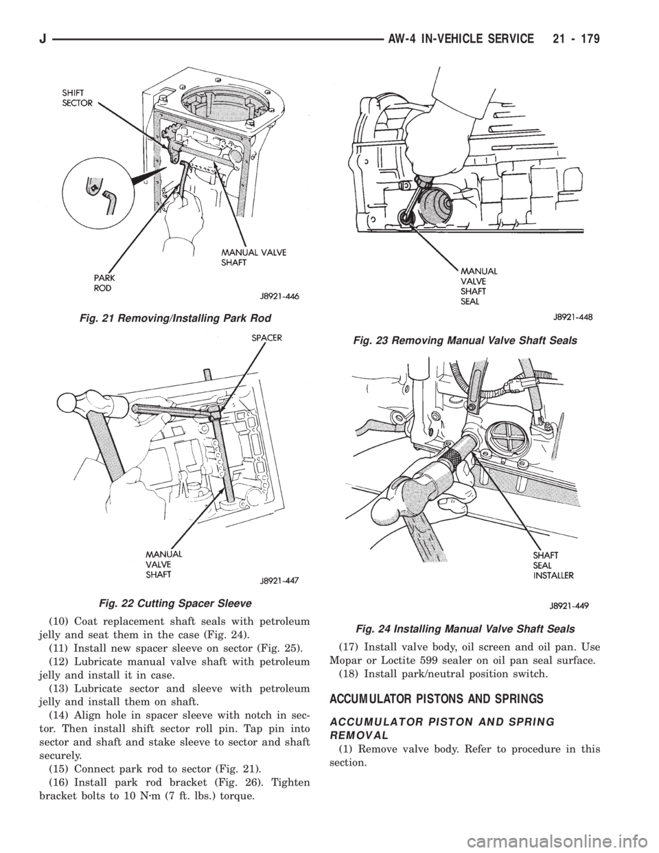
(10) Coat replacement shaft seals with petroleum
jelly and seat them in the case (Fig. 24).
(11) Install new spacer sleeve on sector (Fig. 25).
(12) Lubricate manual valve shaft with petroleum
jelly and install it in case.
(13) Lubricate sector and sleeve with petroleum
jelly and install them on shaft.
(14) Align hole in spacer sleeve with notch in sec-
tor. Then install shift sector roll pin. Tap pin into
sector and shaft and stake sleeve to sector and shaft
securely.
(15) Connect park rod to sector (Fig. 21).
(16) Install park rod bracket (Fig. 26). Tighten
bracket bolts to 10 Nzm (7 ft. lbs.) torque.(17) Install valve body, oil screen and oil pan. Use
Mopar or Loctite 599 sealer on oil pan seal surface.
(18) Install park/neutral position switch.
ACCUMULATOR PISTONS AND SPRINGS
ACCUMULATOR PISTON AND SPRING
REMOVAL
(1) Remove valve body. Refer to procedure in this
section.
Fig. 23 Removing Manual Valve Shaft Seals
Fig. 24 Installing Manual Valve Shaft Seals
Fig. 21 Removing/Installing Park Rod
Fig. 22 Cutting Spacer Sleeve
JAW-4 IN-VEHICLE SERVICE 21 - 179
Page 1298 of 1784
TRANSMISSION COOLER SERVICE
Main Cooler
The transmission main cooler is located in the ra-
diator. The main cooler can be flushed when neces-
sary, however, the cooler is not a repairable
component. If the cooler is damaged, plugged, or
leaking, the radiator will have to be replaced.
Auxiliary Cooler
The auxiliary cooler is mounted in front of the ra-
diator at the driver side of the vehicle (Fig. 48). The
cooler can be flushed when necessary, while mounted
in the vehicle. The cooler can also be removed for ac-
cess, repair, or replacement as needed.
The main and auxiliary coolers should both be
flushed whenever a transmission or converter clutch
malfunction generates sludge, debris, or particles of
clutch friction material.
Cooler Service
The main cooler (and radiator) and the auxiliary
cooler can be removed for service or access to other
components. Auxiliary cooler removal requires that
the front bumper and radiator support be removed
for access to the cooler lines and attaching bracket.
REVERSE FLUSHING MAIN AND AUXILIARY
COOLERS AND COOLER LINES
Reverse flushing the cooler and lines will prevent
sludge and particles from flowing back into the
transmission after repair. The flushing procedure ap-
plies to standard (in-radiator) coolers and auxiliary
coolers equally.
Pressure equipment is preferred for reverse flush-
ing. However, reverse flushing can be performed us-
ing hand operated equipment as described in the
following procedure.
(1) Disconnect cooler lines at transmission and at
auxiliary cooler (Figs. 48 and 49).
(2) Position drain pan under cooler line to catch
material flushed through coolers and lines.
(3) Reverse flush each cooler using hand operated
suction gun filled with mineral spirits. Insert gun
nozzle (or hose) into cooler inlet (return) line. Then
force mineral spirits through into line and through
cooler.(4) Continue reverse flushing until fluid exiting in-
let (pressure) line is clear and free of debris/residue.
(5) Replace radiator if fluid cannot be pumped
through main cooler. Replace auxiliary cooler if leaks
are evident, or if fluid cannot be pumped through it.
(6) Clear flushing materials from coolers and lines
with short pulses of compressed air. Insert air gun
nozzle into cooler inlet (return) line and continue
short pulses of air until all fluid is cleared from
cooler and lines.
(7) Pump one quart of fresh automatic transmis-
sion fluid through cooler and lines before reconnect-
ing cooler lines.
FLOW TESTING TRANSMISSION MAIN
COOLER
Cooler flow is checked by measuring the amount of
fluid flow through the cooler in a 20 second time pe-
riod. The test is performed with the engine running
and transmission in neutral. Fluid is then pumped
through the cooler by the transmission oil pump.
(1) Disconnect cooler inlet line at transmission fit-
ting.
(2) Securely attach hose to end of inlet line and po-
sition line in a one quart test container.
(3) Add extra quart of fluid to transmission.
(4) Use stopwatch to check flow test time.
(5) Shift transmission into neutral and set parking
brake.
(6) Start and run engine at curb idle speed and im-
mediately note cooler flow. Approximately one quart
of fluid should flow into test container in 20 second
period.
(7) If cooler flow is intermittent, flows less than
one quart in 20 seconds, or does not flow at all,
cooler is faulty and must be replaced.
TRANSMISSION COOLER LINE FITTINGS
Quick disconnect fittings are used at the transmis-
sion cooler line connections. The fitting seals and
guides are serviceable.
Replace the seals and guides whenever the fittings
exhibit leakage, or will not properly snap into place.
JAW-4 IN-VEHICLE SERVICE 21 - 187
Page 1300 of 1784
AW-4 TRANSMISSION REMOVAL AND INSTALLATION
INDEX
page page
Oil Pump Seal Replacement............... 189
Torque Converter Stator Clutch Inspection..... 189Transmission and Torque Converter Installation . 190
Transmission and Torque Converter Removal . . 189
TRANSMISSION AND TORQUE CONVERTER
REMOVAL
(1) Raise vehicle.
(2) Drain transmission fluid and reinstall oil pan
drain plug.
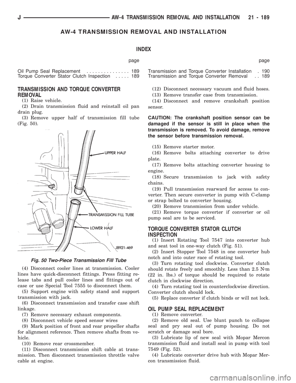
(3) Remove upper half of transmission fill tube
(Fig. 50).
(4) Disconnect cooler lines at transmission. Cooler
lines have quick-disconnect fittings. Press fitting re-
lease tabs and pull cooler lines and fittings out of
case or use Special Tool 7555 to disconnect them.
(5) Support engine with safety stand and support
transmission with jack.
(6) Disconnect transmission and transfer case shift
linkage.
(7) Remove necessary exhaust components.
(8) Disconnect vehicle speed sensor wires
(9) Mark position of front and rear propeller shafts
for alignment reference. Then remove shafts from ve-
hicle.
(10) Remove rear crossmember.
(11) Disconnect transmission shift cable at trans-
mission. Then disconnect transmission throttle valve
cable at engine.(12) Disconnect necessary vacuum and fluid hoses.
(13) Remove transfer case from transmission.
(14) Disconnect and remove crankshaft position
sensor.
CAUTION: The crankshaft position sensor can be
damaged if the sensor is still in place when the
transmission is removed. To avoid damage, remove
the sensor before transmission removal.
(15) Remove starter motor.
(16) Remove bolts attaching converter to drive
plate.
(17) Remove bolts attaching converter housing to
engine.
(18) Secure transmission to jack with safety
chains.
(19) Pull transmission rearward for access to con-
verter. Then secure converter in pump with C-clamp
or strap bolted to converter housing.
(20) Remove transmission from under vehicle.
(21) Remove torque converter if converter or oil
pump seal are to be serviced.
TORQUE CONVERTER STATOR CLUTCH
INSPECTION
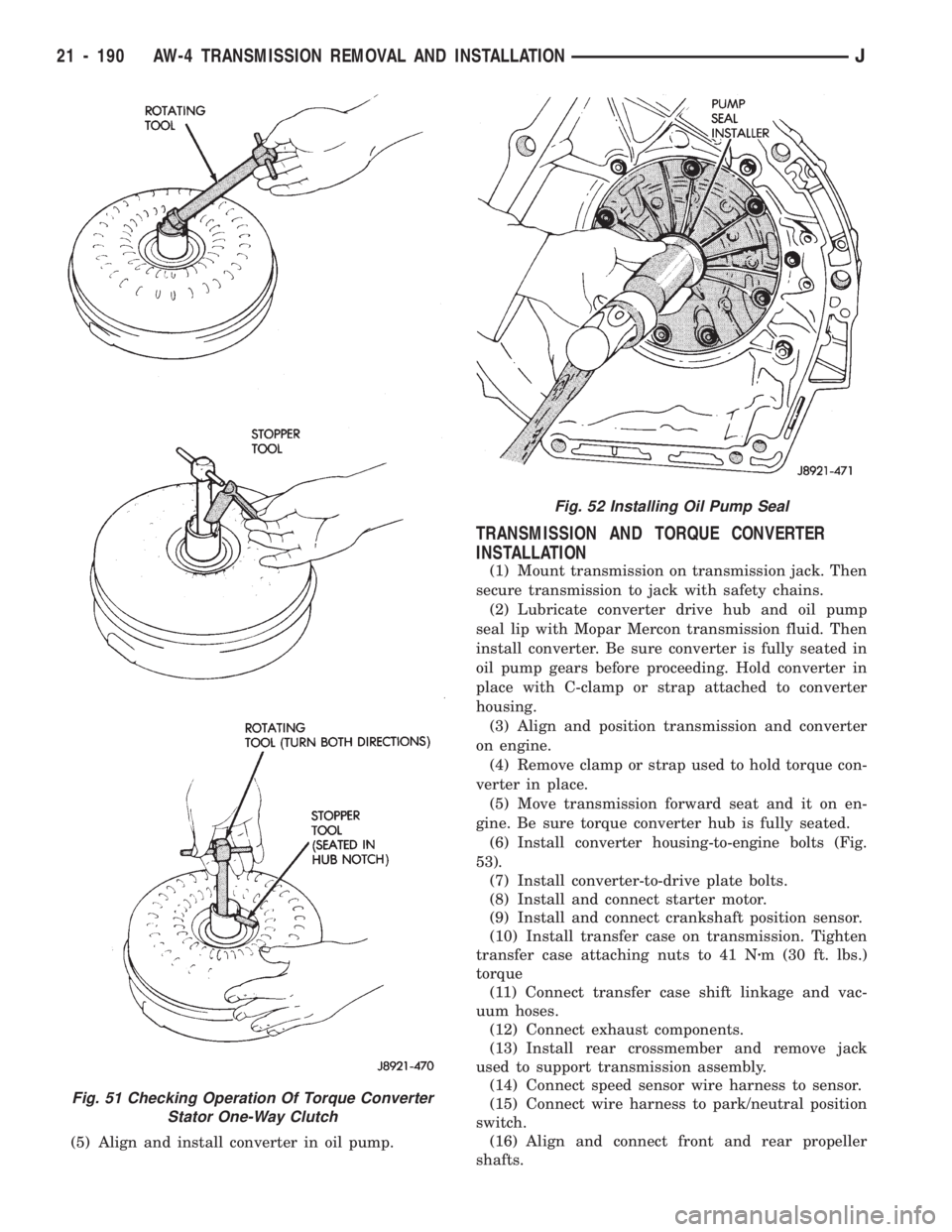
(1) Insert Rotating Tool 7547 into converter hub
and seat tool in one-way clutch (Fig. 51).
(2) Insert Stopper Tool 7548 in one converter hub
notch and into outer race of rotating tool.
(3) Turn rotating tool clockwise. Converter clutch
should rotate freely and smoothly. Less than 2.5 Nzm
(22 in. lbs.) of torque should be required to rotate
clutch in clockwise direction.
(4) Turn rotating tool in counterclockwise direction.
Converter clutch should lock.
(5)
Replace converter if clutch binds or will not lock.
OIL PUMP SEAL REPLACEMENT
(1) Remove converter.
(2) Remove old seal. Use blunt punch to collapse
seal and pry seal out of pump housing. Do not
scratch or damage seal bore.
(3) Lubricate lip of new seal with Mopar Mercon
transmission fluid and install seal in pump with tool
7549 (Fig. 52).
(4) Lubricate converter drive hub with Mopar Mer-
con transmission fluid.
Fig. 50 Two-Piece Transmission Fill Tube
JAW-4 TRANSMISSION REMOVAL AND INSTALLATION 21 - 189
Page 1301 of 1784
(5) Align and install converter in oil pump.
TRANSMISSION AND TORQUE CONVERTER
INSTALLATION
(1) Mount transmission on transmission jack. Then
secure transmission to jack with safety chains.
(2) Lubricate converter drive hub and oil pump
seal lip with Mopar Mercon transmission fluid. Then
install converter. Be sure converter is fully seated in
oil pump gears before proceeding. Hold converter in
place with C-clamp or strap attached to converter
housing.
(3) Align and position transmission and converter
on engine.
(4) Remove clamp or strap used to hold torque con-
verter in place.
(5) Move transmission forward seat and it on en-
gine. Be sure torque converter hub is fully seated.
(6)
Install converter housing-to-engine bolts (Fig.
53).
(7) Install converter-to-drive plate bolts.
(8) Install and connect starter motor.
(9) Install and connect crankshaft position sensor.
(10) Install transfer case on transmission. Tighten
transfer case attaching nuts to 41 Nzm (30 ft. lbs.)
torque
(11) Connect transfer case shift linkage and vac-
uum hoses.
(12) Connect exhaust components.
(13) Install rear crossmember and remove jack
used to support transmission assembly.
(14) Connect speed sensor wire harness to sensor.
(15) Connect wire harness to park/neutral position
switch.
(16) Align and connect front and rear propeller
shafts.
Fig. 51 Checking Operation Of Torque Converter
Stator One-Way Clutch
Fig. 52 Installing Oil Pump Seal
21 - 190 AW-4 TRANSMISSION REMOVAL AND INSTALLATIONJ
Page 1356 of 1784
roded. Replace valves, plugs or sleeves that are
scored or worn. Replace oil strainers if cut, torn or
damaged in any way.
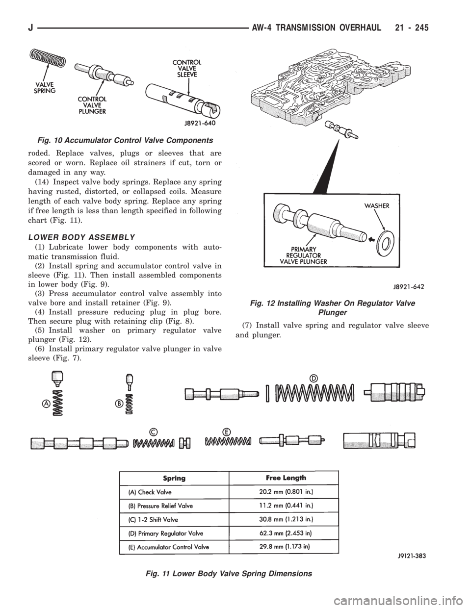
(14) Inspect valve body springs. Replace any spring
having rusted, distorted, or collapsed coils. Measure
length of each valve body spring. Replace any spring
if free length is less than length specified in following
chart (Fig. 11).
LOWER BODY ASSEMBLY
(1) Lubricate lower body components with auto-
matic transmission fluid.
(2) Install spring and accumulator control valve in
sleeve (Fig. 11). Then install assembled components
in lower body (Fig. 9).
(3) Press accumulator control valve assembly into
valve bore and install retainer (Fig. 9).
(4) Install pressure reducing plug in plug bore.
Then secure plug with retaining clip (Fig. 8).
(5) Install washer on primary regulator valve
plunger (Fig. 12).
(6) Install primary regulator valve plunger in valve
sleeve (Fig. 7).(7) Install valve spring and regulator valve sleeve
and plunger.
Fig. 11 Lower Body Valve Spring Dimensions
Fig. 10 Accumulator Control Valve Components
Fig. 12 Installing Washer On Regulator Valve
Plunger
JAW-4 TRANSMISSION OVERHAUL 21 - 245
Page 1379 of 1784
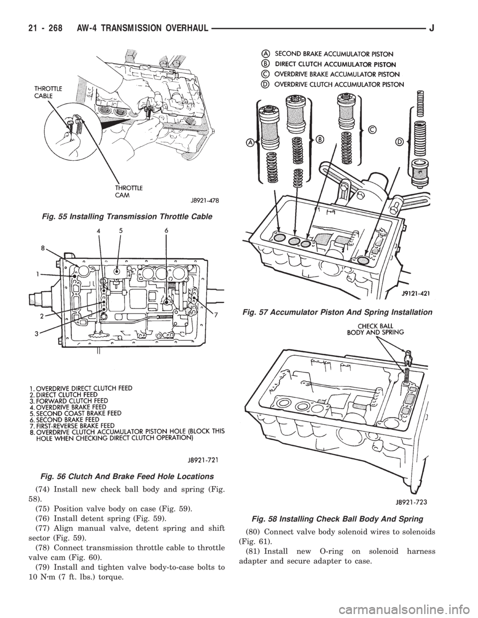
(74) Install new check ball body and spring (Fig.
58).
(75) Position valve body on case (Fig. 59).
(76) Install detent spring (Fig. 59).
(77) Align manual valve, detent spring and shift
sector (Fig. 59).
(78) Connect transmission throttle cable to throttle
valve cam (Fig. 60).
(79) Install and tighten valve body-to-case bolts to
10 Nzm (7 ft. lbs.) torque.(80) Connect valve body solenoid wires to solenoids
(Fig. 61).
(81) Install new O-ring on solenoid harness
adapter and secure adapter to case.
Fig. 57 Accumulator Piston And Spring Installation
Fig. 58 Installing Check Ball Body And Spring
Fig. 55 Installing Transmission Throttle Cable
Fig. 56 Clutch And Brake Feed Hole Locations
21 - 268 AW-4 TRANSMISSION OVERHAULJ
Page 1382 of 1784
valve shaft. Tighten lever attaching nut to 16 Nzm
(12 ft. lbs.) torque.
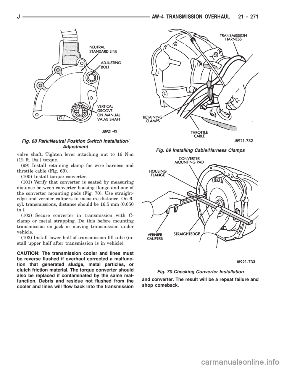
(99) Install retaining clamp for wire harness and
throttle cable (Fig. 69).
(100) Install torque converter.
(101) Verify that converter is seated by measuring
distance between converter housing flange and one of
the converter mounting pads (Fig. 70). Use straight-
edge and vernier calipers to measure distance. On 6-
cyl. transmissions, distance should be 16.5 mm (0.650
in.).
(102) Secure converter in transmission with C-
clamp or metal strapping. Do this before mounting
transmission on jack or moving transmission under
vehicle.
(103) Install lower half of transmission fill tube (in-
stall upper half after transmission is in vehicle).
CAUTION: The transmission cooler and lines must
be reverse flushed if overhaul corrected a malfunc-
tion that generated sludge, metal particles, or
clutch friction material. The torque converter should
also be replaced if contaminated by the same mal-
function. Debris and residue not flushed from the
cooler and lines will flow back into the transmissionand converter. The result will be a repeat failure and
shop comeback.Fig. 69 Installing Cable/Harness Clamps
Fig. 70 Checking Converter Installation
Fig. 68 Park/Neutral Position Switch Installation/
Adjustment
JAW-4 TRANSMISSION OVERHAUL 21 - 271
Page 1386 of 1784
SHIFT LINKAGE ADJUSTMENT
LINKAGE ADJUSTMENTÐYJ
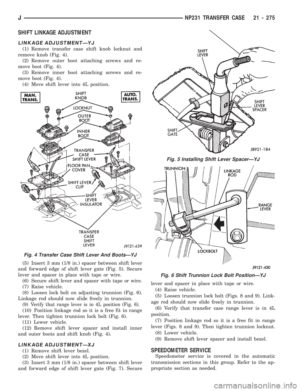
(1) Remove transfer case shift knob locknut and
remove knob (Fig. 4).
(2) Remove outer boot attaching screws and re-
move boot (Fig. 4).
(3) Remove inner boot attaching screws and re-
move boot (Fig. 4).
(4) Move shift lever into 4L position.
(5) Insert 3 mm (1/8 in.) spacer between shift lever
and forward edge of shift lever gate (Fig. 5). Secure
lever and spacer in place with tape or wire.
(6) Secure shift lever and spacer with tape or wire.
(7) Raise vehicle.
(8) Loosen lock bolt on adjusting trunnion (Fig. 6).
Linkage rod should now slide freely in trunnion.
(9) Verify that range lever is in 4L position (Fig. 6).
(10) Position linkage rod so it is a free fit in range
lever. Then tighten trunnion lock bolt (Fig. 6).
(11) Lower vehicle.
(12) Remove shift lever spacer and install inner
and outer boots and shift knob (Fig. 4).
LINKAGE ADJUSTMENTÐXJ
(1) Remove shift lever bezel.
(2) Move shift lever into 4L position.
(3) Insert 3 mm (1/8 in.) spacer between shift lever
and forward edge of shift lever gate (Fig. 7). Securelever and spacer in place with tape or wire.
(4) Raise vehicle.
(5) Loosen trunnion lock bolt (Figs. 8 and 9). Link-
age rod should now slide freely in trunnion.
(6) Verify that transfer case range lever is in 4L
position.
(7) Position linkage rod so it is a free fit in range
lever (Figs. 8 and 9). Then tighten trunnion locknut.
(8) Lower vehicle.
(9) Remove shift lever spacer and install bezel.SPEEDOMETER SERVICE
Speedometer service is covered in the automatic
transmission sections in this group. Refer to the ap-
propriate section as needed.
Fig. 4 Transfer Case Shift Lever And BootsÐYJ
Fig. 5 Installing Shift Lever SpacerÐYJ
Fig. 6 Shift Trunnion Lock Bolt PositionÐYJ
JNP231 TRANSFER CASE 21 - 275