Page 353 of 407
Downloaded from www.Manualslib.com manuals search engine The cast aluminum pistons use two compression rings and one oil control
ring. The pistons are tin plated to provide a non-scuffing surface when
the engine is new.
A steel camshaft is supported by five steel backed babbit bearings. It is
driven
by the crankshaft through a chain at the front of the engine. The
drive gear
is keyed to the crankshaft and the driven sprocket is bolted to
the camshaft. Both the crankshaft gear and camshaft sprocket have
locating marks
to provide the correct valve timing and timing chain
installation. The valve lifters are roller hydraulic type and are positioned
in the aluminum lifter carrier.
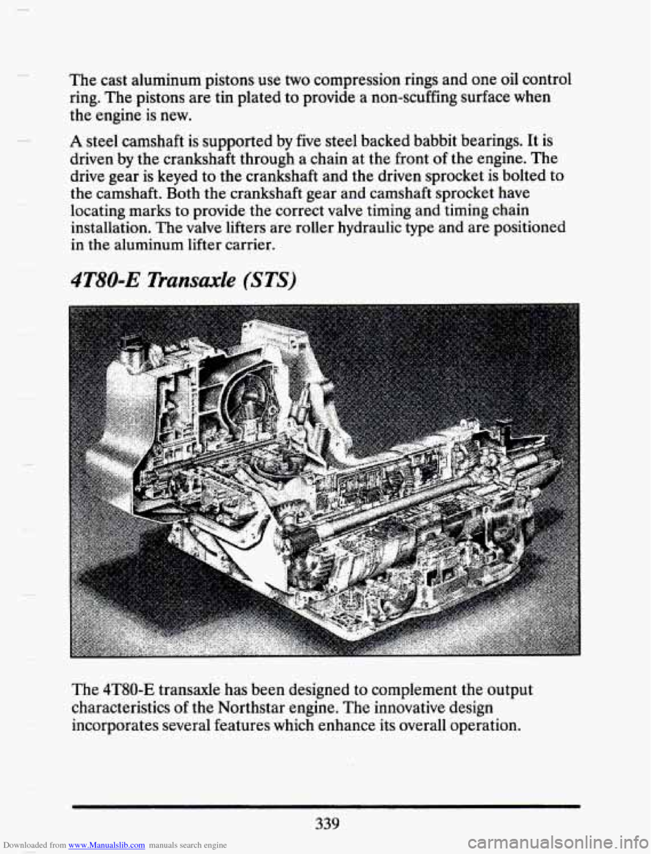
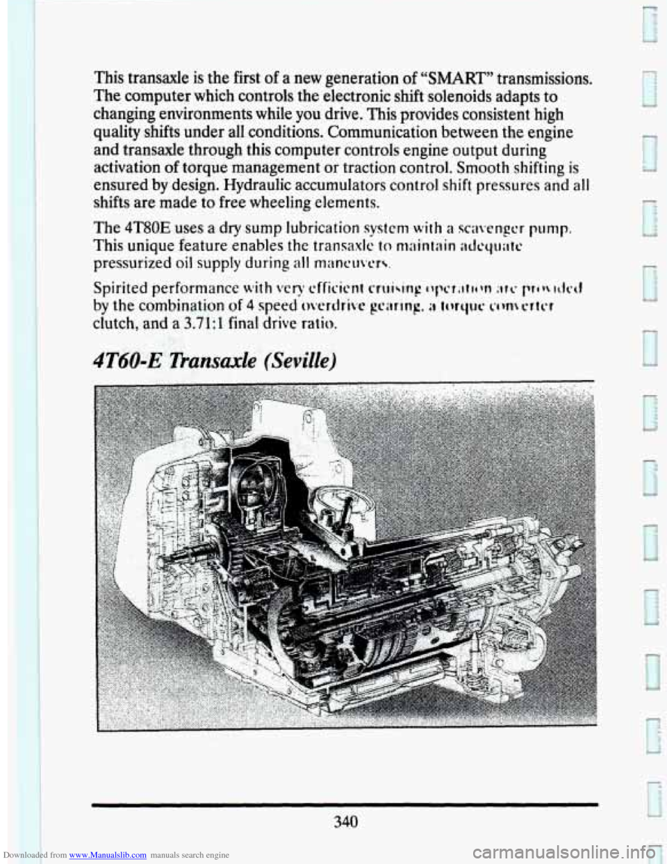
4T80-E Transaxle (STS)
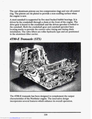
The 4T80-E transaxle has been designed to complement the output
characteristics of the Northstar engine. The innovative design
incorporates several features which enhance its overall operation.
339
Page 354 of 407
Downloaded from www.Manualslib.com manuals search engine This transaxle is the first of a new generation of “SMART” transmissions.
The computer which controls the electronic shift solenoids adapts to
changing environments while you drive. This provides consistent high
quality shifts under all conditions. Communication between the engine
and transaxle through this computer controls engine output during
activation
of torque management or traction control. Smooth shifting is
ensured by design. Hydraulic accumulators control shift pressures and all
shifts are made to free wheeling elements.
The 4T80E uses a
dry sump lubrication system with a scavenger pump.
This unique feature enables the transaxlc to maintain itdcqlriltt!
pressurized oil supply during all mancl~vcr\.
340
Page 355 of 407

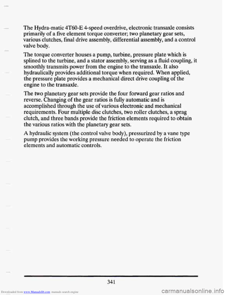
Downloaded from www.Manualslib.com manuals search engine The Hydra-matic 4T60-E 4-speed overdrive, electronic transaxle consists
primarily of a five element torque converter;
two planetary gear sets,
various clutches, final drive assembly, differential assembly, an\
d a control
valve body.
The torque converter houses a pump, turbine, pressure plate which is
splined to the turbine, and a stator assembly, serving as a fluid coupling, it
smoothly transmits power
from the engine to the transaxle. It also
hydraulically provides additional torque
when required. When applied,
the pressure plate provides a mechanical direct drive coupling of the
engine to the transaxle.
The
two planetary gear sets provide the four forward gear ratios and
reverse. Changing of the gear ratios is
fully automatic and is
accomplished through the use
of various electronic and mechanical
requirements. Four multiple disc clutches,
two roller clutches, a sprag
clutch, and three bands provide the friction elements required to obtain
the various ratios with the planetary gear sets.
A hydraulic system (the control valve body), pressurized by a vane type
pump provides the working pressure needed to operate the friction
elements and automatic controls.
341
Page 356 of 407
Downloaded from www.Manualslib.com manuals search engine Front Suspension
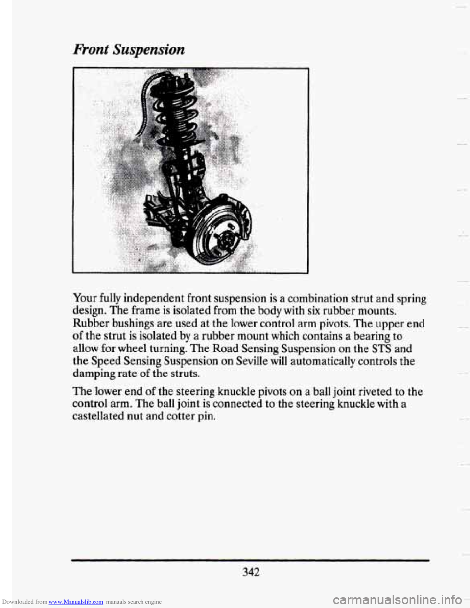
Your fully independent front suspension is a combination strut and sp~
design. The frame is isolated from the body with six rubber mounts. -ing
Rubber bushings are used at the lower control arm pivots. The upper
end
of the strut is isolated by a rubber mount which contains a bearing to
allow for wheel turning. The Road Sensing Suspension
on the STS and
the Speed Sensing Suspension on Seville
will automatically controls the
damping rate
of the struts.
The lower end
of the steering knuckle pivots on a ball joint riveted to the
control arm. The ball joint is connected to the steering knuckle with a
castellated nut and cotter pin.
342
Page 357 of 407

Downloaded from www.Manualslib.com manuals search engine ShortlLong Arm Suspension (SLA)
r
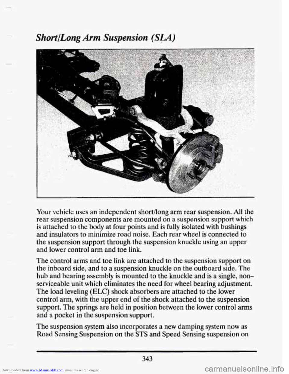
Your vehicle uses an independent shortfiong arm rear suspension. All the
rear suspension components are mounted
on a suspension support which
is attached to the
body at four points and is fully isolated with bushings
and insulators to minimize road noise. Each rear wheel is connected to
the suspension support through the suspension knuckle using an upper
and lower control arm and toe link.
The control arms and toe link are attached to the suspension support on
the inboard side, and to a suspension knuckle on the outboard side. The
hub and bearing assembly is mounted to the knuckle and is a single, non-
serviceable unit which eliminates the need for wheel bearing adjustment.
The load leveling
(ELC) shock absorbers are attached to the lower
control arm, with the upper end
of the shock attached to the suspension
support.
The springs are held in position between the lower control arms
and a pocket in the suspension support.
The suspension system also incorporates
a new damping system now as
Road Sensing Suspension on the
STS and Speed Sensing suspension on
343
Page 358 of 407

Downloaded from www.Manualslib.com manuals search engine the Seville. These systems control the damping forces in the shock
absorbers and struts,
in response to various road and driving conditions.
The systems are capable of
making these damping changes extremely fast.
A computer receives inputs from vertical acceleration sensors, whee\
l to
body position sensors, vehicle speed sensor,
lift and dive signals. This
computer evaluates the inputs from these sensors, to control the damping
of each of the struts and shocks independently to provide varied levels of
suspension control.
The system also has the capability of providing Speed Sensitive Ste\
ering
control. This system changes your steering effort based on your\
vehicle
speed.
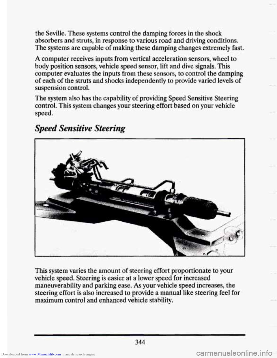
Speed Sensitive Steering
This system varies the amount of steering effort proportionate to your
vehicle speed. Steering is easier at
a lower speed for increased
maneuverability and parking ease.
As your vehicle speed increases, the
steering effort is also increased to provide a manual like steering feel for
maximum control and enhanced vehicle stability.
344
.-
A
Page 359 of 407

Downloaded from www.Manualslib.com manuals search engine The power rack and pinion steering system has a rotary spool valve which
directs hydraulic fluid coming from the power steering pump to one side
or the other side
of the rack piston. The integral rack piston is attached to
the rack. The rack piston converts hydraulic pressure to a linear force
which moves the rack left or right. The force is then transmitted through
the inner and outer tie rods to the steering knuckles, which turn the
wheels
If hydraulic assist
is not available, manual control is maintained. However
under these conditions more steering effort is required.
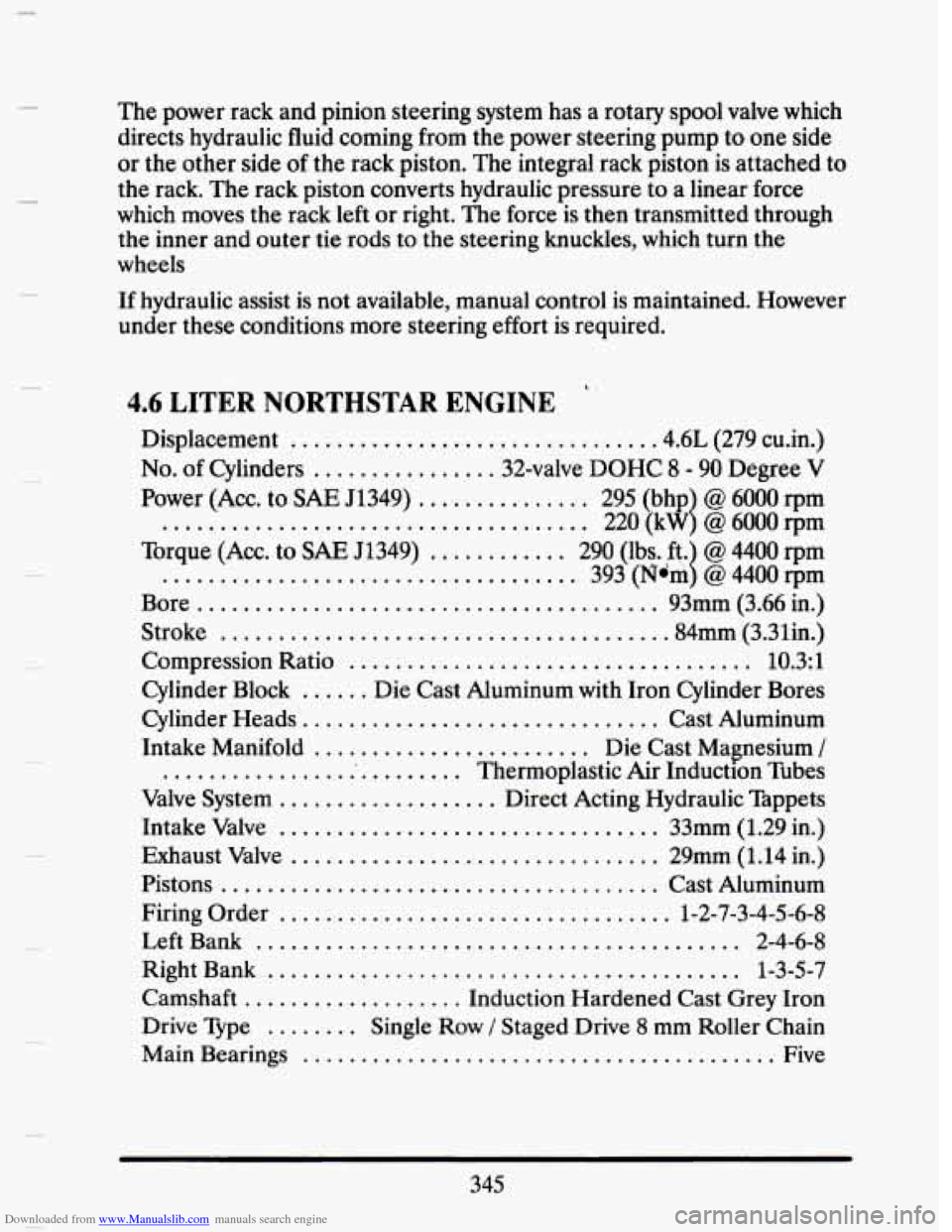
4.6 LITER NORTHSTAR ENGINE
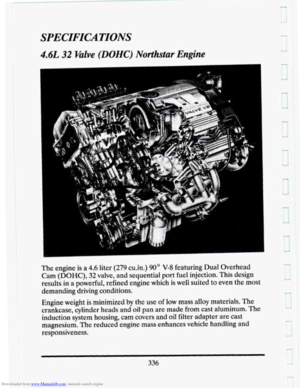
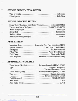
Displacement ............................... .4.6L (279 cu.in.)
No. of Cylinders ................ 32-valve DOHC 8 - 90 Degree V
Power (Acc.
to SAE 51349) ............... 295 (bhp @ 6000 rpm
..................................... 220 (kW @ 6000rpm
Torque (ACC. to
SAE 51349) ............ 290 (lbs. ft. @ 4400 rpm
Bore ........................................ 93mm (3.66 in.)
Stroke
...................................... .84mm (3.31in.)
Compression Ratio
................................... 10.3:l
Cylinder Heads ............................... Cast Aluminum
Intake Manifold
........................ Die Cast Magnesium /
........................... Thermoplastic Air Induction nbes
Valve System
................... Direct Acting Hydraulic Tappets
Intake Valve
................................. 33mm (1.29 in.)
Exhaust Valve
................................ 29mm (1.14 in.)
Pistons
...................................... Cast Aluminum
Firing Order
.................................. 1-2-7-3-4-5-6-8
Left Bank
.......................................... 2-4-6-8
Right Bank
......................................... 1-3-5-7
Camshaft
................... Induction Hardened Cast Grey Iron
Drive Type
........ Single Row / Staged Drive 8 mm Roller Chain
Main Bearings
......................................... Five
1
1 .................................... 393 (Ndm @ 4400 rpm
Cylinder Block
...... Die Cast Aluminum with Iron Cylinder Bores
345
Page 360 of 407

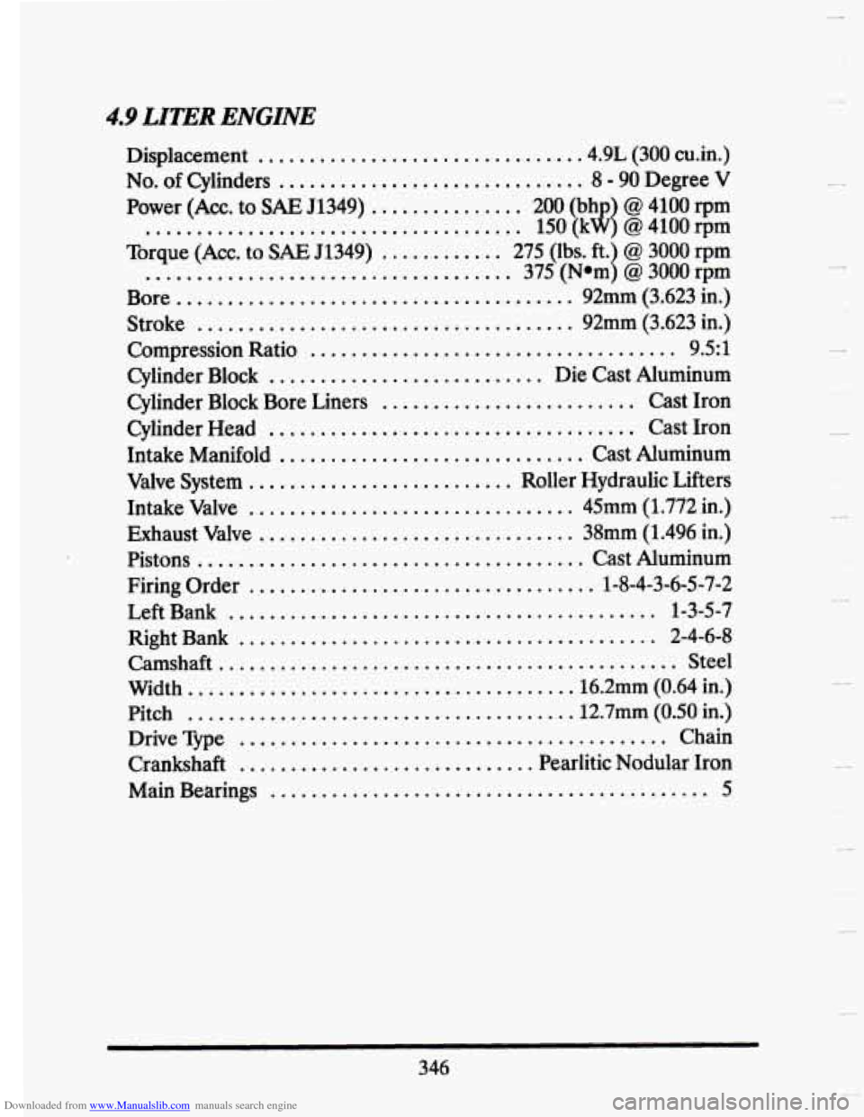
Downloaded from www.Manualslib.com manuals search engine 4.9 LITER ENGINE
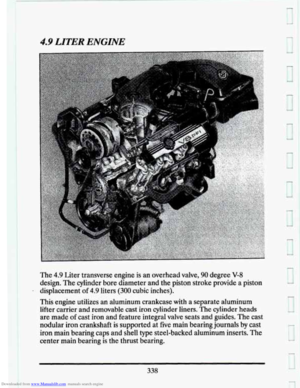
Displacement ............................... .4.9L (300 cuin.)
No.
of Cylinders .............................. 8 - 90 Degree V
Power (Acc. to SAE 51349) ............... 200 (bhp @ 4100 rpm
Torque (ACC.
to SAE 51349) ............ 275 (lbs. ft. @ 3000 rpm
Bore
....................................... 92mm (3.623 in.)
Stroke
..................................... 92mm (3.623 in.)
Compression Ratio
.................................... 9.5: 1
Cyiinder Block ........................... Die Cast Aluminum
Cylinder Block Bore Liners
......................... Cast Iron
Cylinder Head
.................................... Cast Iron
Intake Manifold
.............................. Cast Aluminum
Valve System
.......................... Roller Hydraulic Lifters
Intake Valve
................................ 45mm (1.772 in.)
Exhaust Valve
............................... 38mm (1.496 in.)
Pistons
...................................... Cast Aluminum
Firing Order
.................................. 1-8-4-3-6-5-7-2
Left Bank
.......................................... 1-3-5-7
Right Bank
......................................... 2-4-6-8
Camsha
............................................... Steel
Width.
..................................... 16.2mm (0.64 in.)
Pitch
..................................... .12.7mm (0.50 in.)
Drive Vpe
.......................................... Chain
Crankshaft
............................. Pearlitic Nodular Iron
..................................... 150 (kW @ 4100 rpm
.................................... 375 (Nom @ 3000 rpm
1
1
I
Main Bearings ........................................... 5
346