Page 1202 of 1640
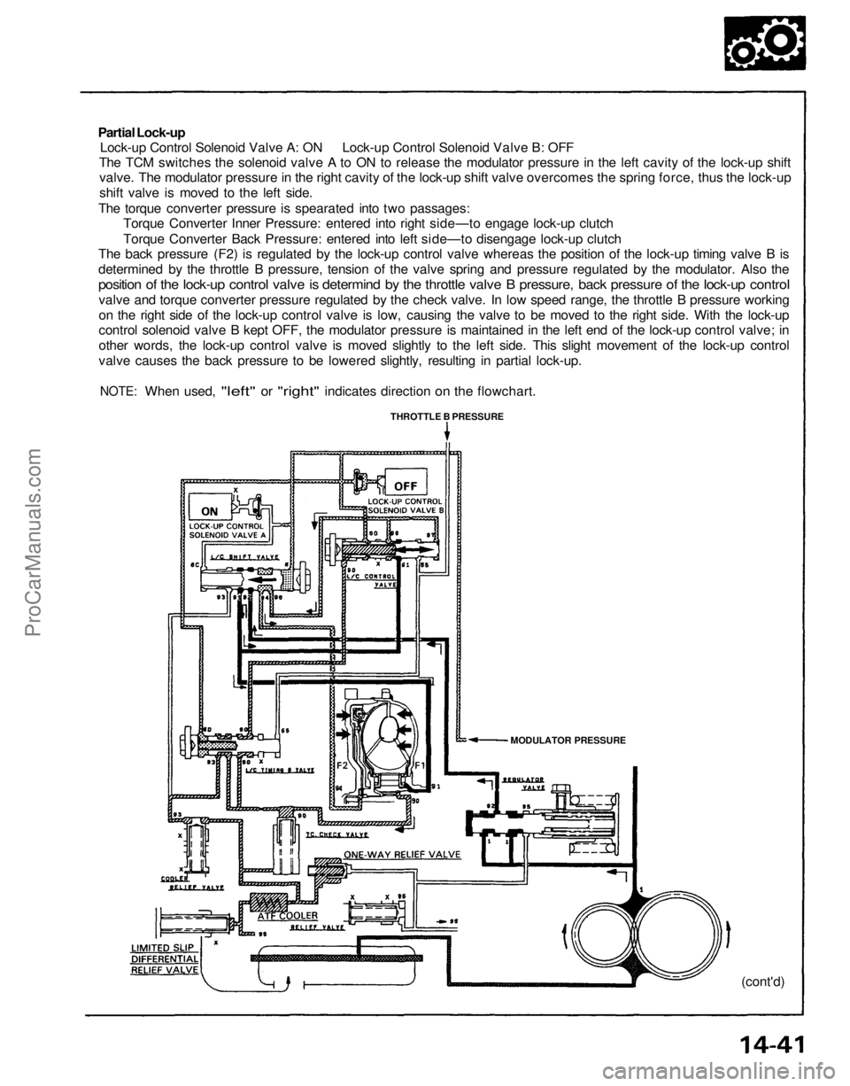
Partial Lock-up
Lock-up Control Solenoid Valve A: ON Lock-up Control Solenoid Valve B: OFF
The TCM switches the solenoid valve A to ON to release the modulator pressure in the left cavity of the lock-up shift
valve. The modulator pressure in the right cavity of the lock-up shift valve overcomes the spring force, thus the lock-up
shift valve is moved to the left side.
The torque converter pressure is spearated into two passages:
Torque Converter Inner Pressure: entered into right side—to engage lock-up clutch
Torque Converter Back Pressure: entered into left side—to disengage lock-up clutch
The back pressure (F2) is regulated by the lock-up control valve whereas the position of the lock-up timing valve B is
determined by the throttle B pressure, tension of the valve spring and pressure regulated by the modulator. Also the
position of the lock-up control valve is determind by the throttle valve B pressure, back pressure of the lock-up control
valve and torque converter pressure regulated by the check valve. In low speed range, the throttle B pressure working
on the right side of the lock-up control valve is low, causing the valve to be moved to the right side. With the lock-up
control solenoid valve B kept OFF, the modulator pressure is maintained in the left end of the lock-up control valve; in
other words, the lock-up control valve is moved slightly to the left side. This slight movement of the lock-up control
valve causes the back pressure to be lowered slightly, resulting in partial lock-up.
NOTE:
When used,
"left"
or
"right"
indicates direction
on the
flowchart.
THROTTLE B PRESSURE
MODULATOR PRESSURE
(cont'd)ProCarManuals.com
Page 1204 of 1640
Full Lock-up
Lock-up Control Solenoid Valve A: ON Lock-up Control Solenoid Valve B: ON
When the vehicle speed further increases, the throttle B pressure is increased in accordance with the throttle opening.
The lock-up timing valve B overcomes the spring force and moves to the left side. Also this valve closes the oil port
leading to the torque converter check valve.
Under this condition, the throttle B pressure working on the right end of the lock-up control valve becomes greater than
that on the left end (modulator pressure in the left end has already been released by the solenoid valve B); i. e., the lock-
up control valve is moved to the left side. As this happens, the torque converter back pressure is released fully, causing
the lock-up clutch to be engaged fully.
NOTE: When used,
"left"
or
"right"
indicates direction
on the
flowchart.
MODULATOR PRESSURE
(cont'd)
THROTTLE B PRESSUREProCarManuals.com
Page 1205 of 1640
Description
Lock-up System (cont'd)
Deceleration Lock-up
Lock-up Control Solenoid Valve A: ON Lock-up Control Solenoid Valve B: Duty Operation (ON OFF)
The TCM switches the solenoid valve B to ON and OFF alternately at high speeds under certain conditions.
The slight lock-up and half lock-up regions are maintained so as to lock the torque converter properly.
NOTE:
When used,
"left"
or
"right"
indicates direction
on the
flow chart.
MODULATOR PRESSURE
THROTTLE B PRESSUREProCarManuals.com
Page 1224 of 1640
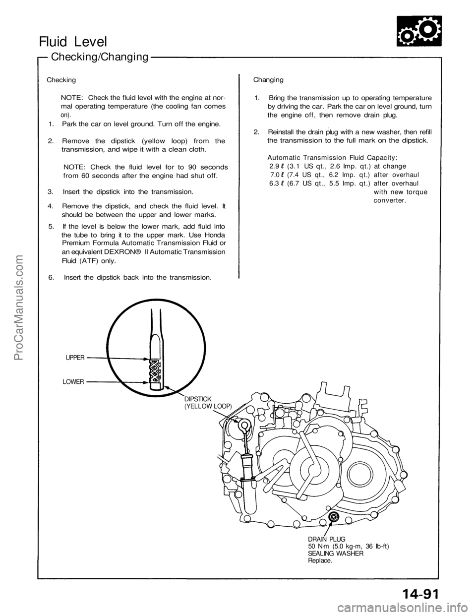
Fluid Level
Checking/Changing
Checking
NOTE: Check the fluid level with the engine at nor-
mal operating temperature (the cooling fan comes
on).
1. Park the car on level ground. Turn off the engine.
2. Remove the dipstick (yellow loop) from the
transmission, and wipe it with a clean cloth.
NOTE: Check the fluid level for to 90 seconds
from 60 seconds after the engine had shut off.
3. Insert the dipstick into the transmission.
4. Remove the dipstick, and check the fluid level. It
should be between the upper and lower marks.
5. If the level is below the lower mark, add fluid into
the tube to bring it to the upper mark. Use Honda
Premium Formula Automatic Transmission Fluid or
an equivalent DEXRON® II Automatic Transmission
Fluid (ATF) only.
6. Insert the dipstick back into the transmission.
UPPER
LOWER
DIPSTICK
(YELLOW LOOP)
DRAIN PLUG
50 N·m (5.0 kg-m, 36 Ib-ft)
SEALING WASHER
Replace.
Changing
1. Bring the transmission up to operating temperature
by driving the car. Park the car on level ground, turn
the engine off, then remove drain plug.
2. Reinstall the drain plug with a new washer, then refill
the transmission to the full mark on the dipstick.
Automatic Transmission Fluid Capacity:
2.9 (3.1 US qt., 2.6 Imp. qt.) at change
7.0 (7.4 US qt., 6.2 Imp. qt.) after overhaul
6.3 (6.7 US qt., 5.5 Imp. qt.) after overhaul
with new torque
converter.ProCarManuals.com
Page 1225 of 1640
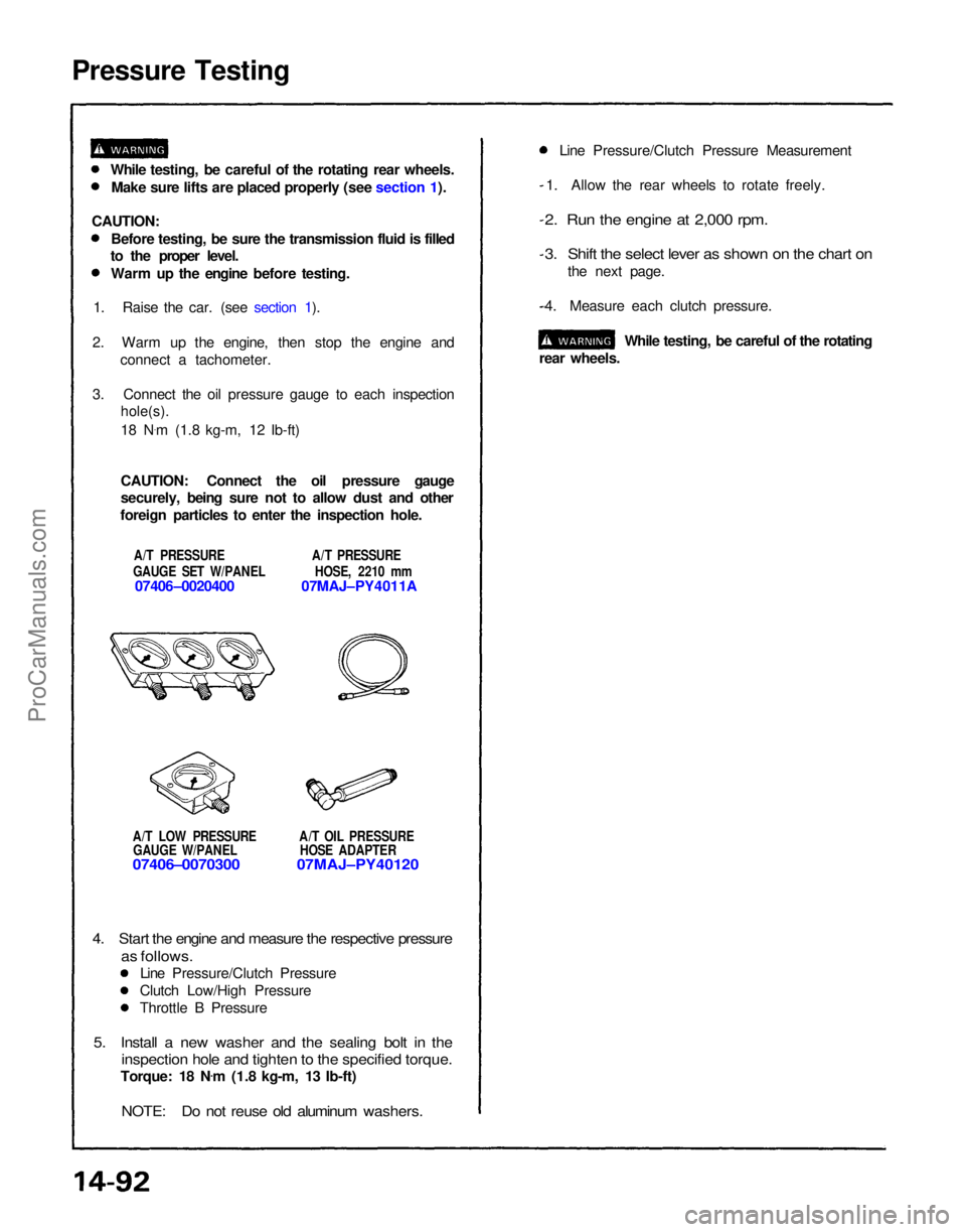
Pressure Testing
A/T LOW PRESSURE A/T OIL PRESSUREGAUGE W/PANEL HOSE ADAPTER
07406–0070300 07MAJ–PY40120
1. Allow the rear wheels to rotate freely.
2. Run the engine at 2,000 rpm.
3. Shift the select lever as shown on the chart on
the next page.
4. Measure each clutch pressure.
While testing, be careful of the rotating
rear wheels.
4. Start the engine and measure the respective pressure
as follows.
Line Pressure/Clutch Pressure
Clutch Low/High Pressure
Throttle B Pressure
5. Install a new washer and the sealing bolt in the
inspection hole and tighten to the specified torque.
Torque: 18 N .
m (1.8 kg-m, 13 Ib-ft)
NOTE: Do not reuse old aluminum washers.
While testing, be careful of the rotating rear wheels.
Make sure lifts are placed properly (see section 1).
CAUTION: Before testing, be sure the transmission fluid is filled
to the proper level.
Warm up the engine before testing.
1. Raise the car. (see section 1).
2. Warm up the engine, then stop the engine and connect a tachometer.
3. Connect the oil pressure gauge to each inspection
hole(s).
18 N .
m (1.8 kg-m, 12 Ib-ft)
CAUTION: Connect the oil pressure gauge
securely, being sure not to allow dust and other
foreign particles to enter the inspection hole.
A/T PRESSURE A/T PRESSURE
GAUGE SET W/PANEL HOSE, 2210 mm
07406–0020400 07MAJ–PY4011A Line Pressure/Clutch Pressure MeasurementProCarManuals.com
Page 1232 of 1640
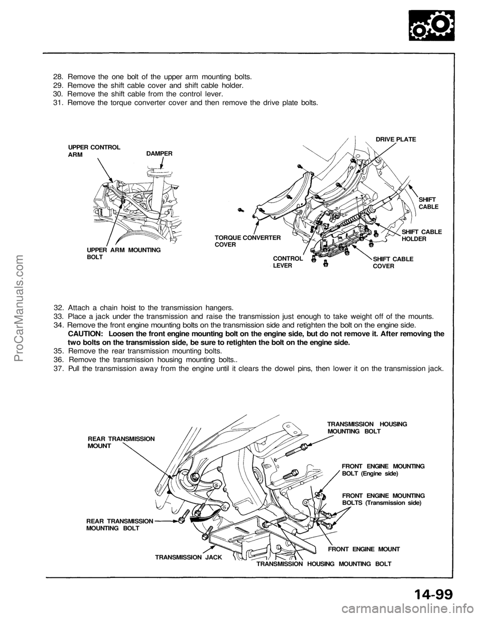
28. Remove the one bolt of the upper arm mounting bolts.
29. Remove the shift cable cover and shift cable holder.
30. Remove the shift cable from the control lever.
31. Remove the torque converter cover and then remove the drive plate bolts.
DRIVE PLATE
DAMPER
UPPER CONTROL
ARM
SHIFT
CABLE
SHIFT CABLE
HOLDER
SHIFT CABLE
COVER
CONTROL
LEVER
TORQUE CONVERTER
COVER
UPPER ARM MOUNTING
BOLT
32. Attach a chain hoist to the transmission hangers.
33. Place a jack under the transmission and raise the transmission just enough to take weight off of the mounts.34. Remove the front engine mounting bolts on the transmission side and retighten the bolt on the engine side.
CAUTION: Loosen the front engine mounting bolt on the engine side, but do not remove it. After removing the
two bolts on the transmission side, be sure to retighten the bolt on the engine side.
35. Remove the rear transmission mounting bolts.
36. Remove the transmission housing mounting bolts..
37. Pull the transmission away from the engine until it clears the dowel pins, then lower it on the transmission jack.
TRANSMISSION HOUSINGMOUNTING BOLT
FRONT ENGINE MOUNTINGBOLT (Engine side)
FRONT ENGINE MOUNTING
BOLTS (Transmission side)
FRONT ENGINE MOUNT
TRANSMISSION HOUSING MOUNTING BOLT
TRANSMISSION JACK
REAR TRANSMISSION
MOUNTING BOLT REAR TRANSMISSION
MOUNTProCarManuals.com
Page 1234 of 1640
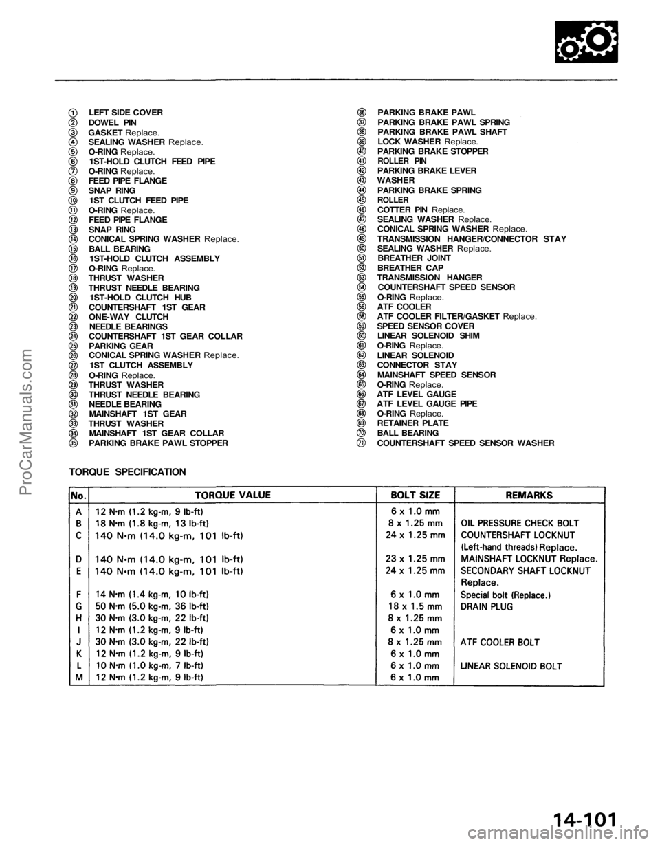
LEFT SIDE COVER
DOWEL PIN
GASKET Replace.
SEALING WASHER
Replace.
O-RING
Replace.
1ST-HOLD CLUTCH FEED PIPE
O-RING
Replace.
FEED PIPE FLANGE
SNAP RING
1ST CLUTCH FEED PIPE
O-RING
Replace.
FEED PIPE FLANGE
SNAP RING
CONICAL SPRING WASHER
Replace.
BALL BEARING
1ST-HOLD CLUTCH ASSEMBLY
O-RING
Replace.
THRUST WASHER
THRUST NEEDLE BEARING
1ST-HOLD CLUTCH HUB
COUNTERSHAFT 1ST GEAR
ONE-WAY CLUTCH NEEDLE BEARINGS
COUNTERSHAFT 1ST GEAR COLLAR
PARKING GEAR
CONICAL SPRING WASHER
Replace.
1ST CLUTCH ASSEMBLY
O-RING
Replace.
THRUST WASHER
THRUST NEEDLE BEARING
NEEDLE BEARINGMAINSHAFT 1ST GEAR
THRUST WASHER MAINSHAFT 1ST GEAR COLLAR
PARKING BRAKE PAWL STOPPER PARKING BRAKE PAWL
PARKING BRAKE PAWL SPRING
PARKING BRAKE PAWL SHAFT
LOCK WASHER
Replace.
PARKING BRAKE STOPPER
ROLLER PIN
PARKING BRAKE LEVER
WASHER
PARKING BRAKE SPRING
ROLLER
COTTER PIN
Replace.
SEALING WASHER
Replace.
CONICAL SPRING WASHER
Replace.
TRANSMISSION HANGER/CONNECTOR STAY
SEALING WASHER
Replace.
BREATHER JOINT
BREATHER CAP
TRANSMISSION HANGER COUNTERSHAFT SPEED SENSOR
O-RING
Replace.
ATF COOLER
ATF COOLER FILTER/GASKET
Replace.
SPEED SENSOR COVER
LINEAR SOLENOID SHIM
O-RING
Replace.
LINEAR SOLENOID
CONNECTOR STAY
MAINSHAFT SPEED SENSOR
O-RING
Replace.
ATF LEVEL GAUGE
ATF LEVEL GAUGE PIPE
O-RING
Replace.
RETAINER PLATE
BALL BEARING
COUNTERSHAFT SPEED SENSOR WASHER
TORQUE SPECIFICATIONProCarManuals.com
Page 1236 of 1640
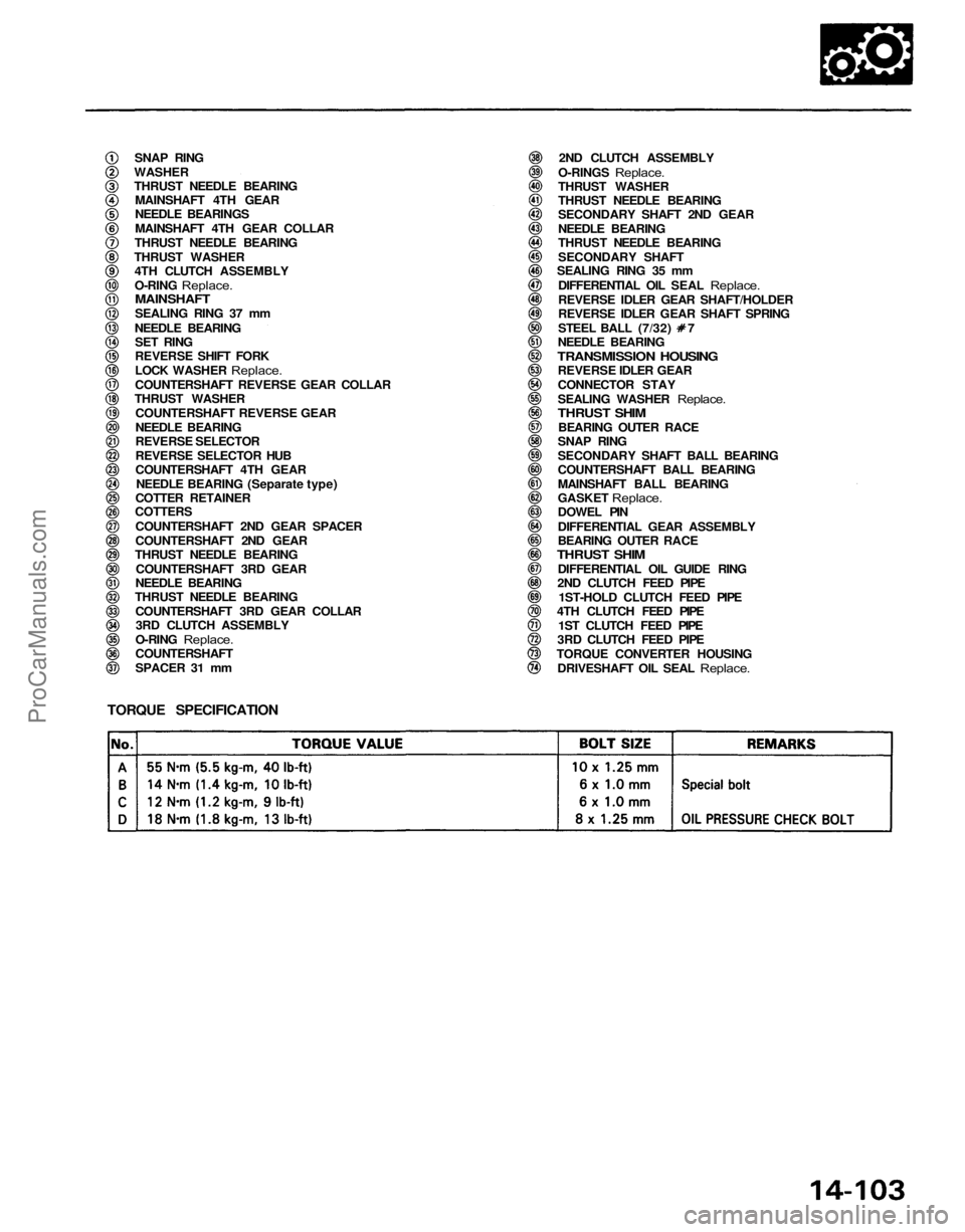
SNAP RING
WASHER
THRUST NEEDLE BEARING MAINSHAFT 4TH GEAR
NEEDLE BEARINGS
MAINSHAFT 4TH GEAR COLLAR
THRUST NEEDLE BEARING
THRUST WASHER 4TH CLUTCH ASSEMBLY
O-RING Replace.
MAINSHAFT
SEALING RING 37 mm
NEEDLE BEARING SET RING
REVERSE SHIFT FORK
LOCK WASHER
Replace.
COUNTERSHAFT REVERSE GEAR COLLAR
THRUST WASHER
COUNTERSHAFT REVERSE GEAR
NEEDLE BEARING
REVERSE SELECTOR
REVERSE SELECTOR HUB
COUNTERSHAFT 4TH GEARNEEDLE BEARING (Separate type)
COTTER RETAINER
COTTERS
COUNTERSHAFT 2ND GEAR SPACER
COUNTERSHAFT 2ND GEAR
THRUST NEEDLE BEARING
COUNTERSHAFT 3RD GEAR
NEEDLE BEARING
THRUST NEEDLE BEARING
COUNTERSHAFT 3RD GEAR COLLAR3RD CLUTCH ASSEMBLY
O-RING
Replace.
COUNTERSHAFT
SPACER 31 mm
2ND CLUTCH ASSEMBLY
O-RINGS
Replace.
THRUST WASHER
THRUST NEEDLE BEARING
SECONDARY SHAFT 2ND GEAR
NEEDLE BEARING
THRUST NEEDLE BEARING
SECONDARY SHAFT
SEALING RING 35 mm
DIFFERENTIAL OIL SEAL
Replace.
REVERSE IDLER GEAR SHAFT/HOLDER
REVERSE IDLER GEAR SHAFT SPRING
STEEL BALL (7/32) 7
NEEDLE BEARING
TRANSMISSION HOUSING
REVERSE IDLER GEAR
CONNECTOR STAY
SEALING WASHER
Replace.
THRUST SHIM
BEARING OUTER RACE
SNAP RING
SECONDARY SHAFT BALL BEARING
COUNTERSHAFT BALL BEARING
MAINSHAFT BALL BEARING
GASKET
Replace.
DOWEL PIN
DIFFERENTIAL GEAR ASSEMBLY
BEARING OUTER RACE
THRUST SHIM
DIFFERENTIAL OIL GUIDE RING
2ND CLUTCH FEED PIPE
1ST-HOLD CLUTCH FEED PIPE
4TH CLUTCH FEED PIPE
1ST CLUTCH FEED PIPE
3RD CLUTCH FEED PIPE
TORQUE CONVERTER HOUSING DRIVESHAFT OIL SEAL
Replace.
TORQUE SPECIFICATIONProCarManuals.com