Page 999 of 1640
Additional Torque Value Specifications:
NOTE: For manifold replacement, refer to section 9.
ENGINE HANGER
8 x
1.25
mm
30 N .
m
(3.0 kg-m,
22 Ib-ft)
A/T TRANSMISSION HANGERS
8 x
1.25
mm
30 N .
m
(3.0 kg-m,
22 Ib-ft)
M/T TRANSMISSION
HANGERS
12 x
1.25
mm
75 N .
m (7.5 kg-m, 54 Ib-ft)
6 x 1.0 mm
10 N .
m (1.0 kg-m, 7 Ib-ft)
8 x
1.25
mm
22 N .
m
(2.2 kg-m,
16 Ib-ft) HALF SHAFT
SUPPORT BASE
(cont'd)
HALF SHAFT
HEAT COVER
8 x
1.25
mm
22 N
.
m
(2.2 kg-m,
16 Ib-ft)
A/C BRACKET
HALF SHAFT
10 x
1.25
mm
45 N .
m
(4.5 kg-m,
33 Ib-ft)
ALTERNATOR
BRACKET
STIFFENER
8 x
1.25
mm
22 N
.
m
(2.2 kg-m,
16 Ib-ft)
8x
1.25
mm
22 N .
m
(2.2 kg-m,
16 Ib-ft)
10 x
1.25
mm
45 N .
m
(4.5 kg-m,
33 Ib-ft)
ALTERNATOR
BRACKET
8 x
1.25
mm
22 N .
m
(2.2 kg-m,
16 Ib-ft)ProCarManuals.com
Page 1000 of 1640
Engine Removal/Installation
(cont'd)
Sub-frame Torque Value Specifications:
RIGHT REAR
BRACKET
10 x
1.25
mm
60 N .
m
(6.0 kg-m.
43 Ib-ft)
LEFT REAR
BRACKET
10 x
1.25
mm
60 N .
m
(6.0 kg-m
43 Ib-ft)
10 x 1.25mm
60 N .
m (6.0 kg-m, 43 Ib-ft)
CORROSION RESISTANT BOLT/NUT
12 x
1.25
mm
95 N.m (9.5 kg-m, 69 Ib-ft)
10 x
1.25
mm
60 N .
m (6.0 kg-m, 43 Ib-ft)
ROD A
10 x
1.25
mm
60 N .
m
(6.0 kg-m,
43 Ib-ft)
FRONT BEAM
REAR BEAM
12 x
1.25
mm
95 N .
m
(9.5 kg-m,
69 Ib-ft) ROD B
10 x
1.25
mm
60 N .
m (6.0 kg-m, 43 Ib-ft)
CENTER RODProCarManuals.com
Page 1002 of 1640
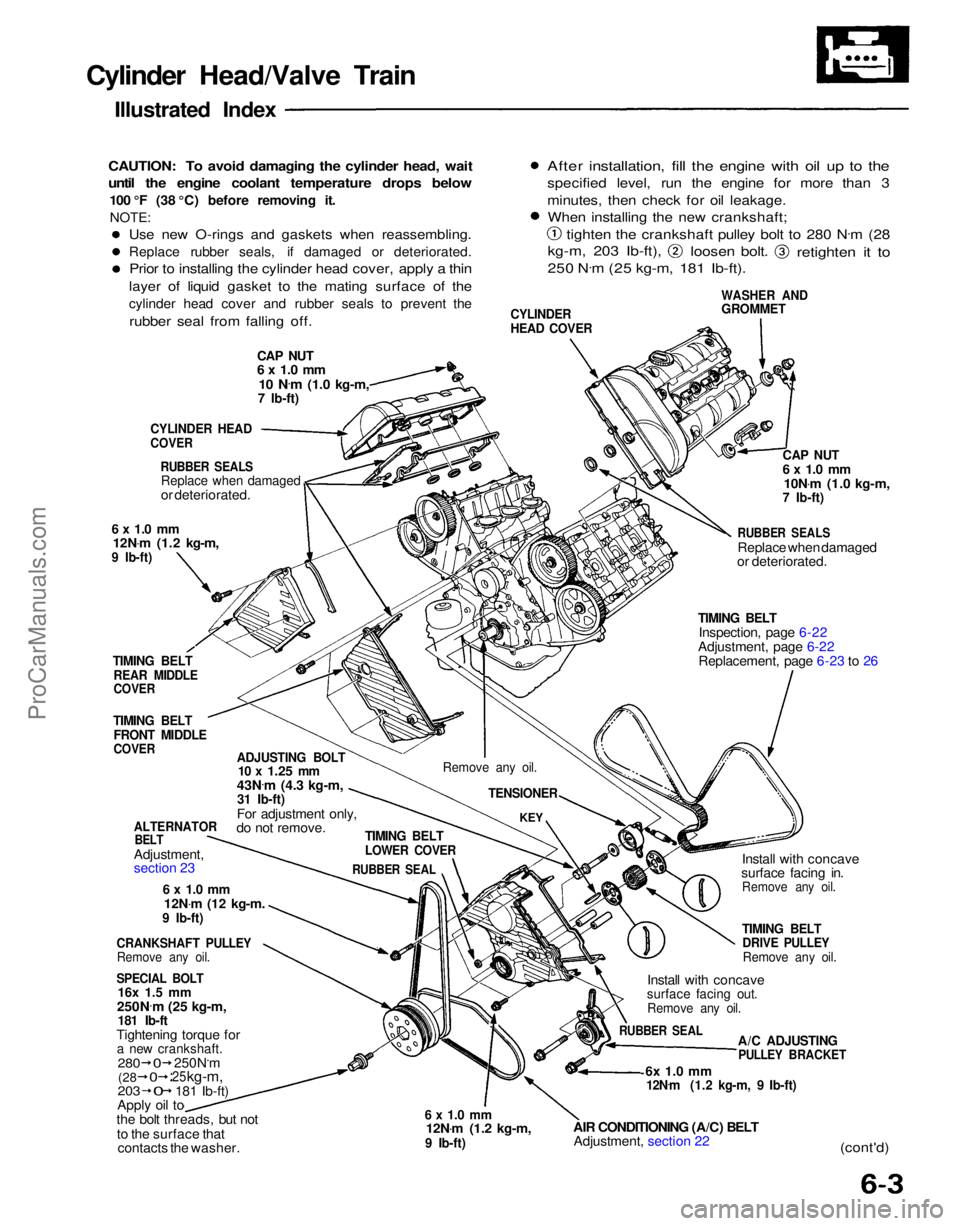
Cylinder Head/Valve Train
Illustrated Index
CAUTION: To avoid damaging the cylinder head, wait
until the engine coolant temperature drops below
100 °F (38 °C) before removing it.NOTE:
CAP NUT
6 x 1.0 mm
10 N .
m
(1.0 kg-m,
7 Ib-ft)
CYLINDER
HEAD COVER
WASHER AND
GROMMET
After installation, fill the engine with oil up to the
specified level, run the engine for more than 3
minutes, then check for oil leakage.
When installing the new crankshaft;
tighten the crankshaft pulley bolt to 280 N .
m (28
kg-m, 203 Ib-ft),
loosen bolt.
retighten it to
250 N .
m (25 kg-m, 181 Ib-ft).
CYLINDER HEAD
COVER
RUBBER SEALS
Replace when damaged
or deteriorated.
6 x 1.0 mm
12N .
m (1.2 kg-m,
9 Ib-ft)
TIMING BELT
REAR MIDDLE
COVER
TIMING BELT
FRONT MIDDLE
COVER
ADJUSTING BOLT
10 x
1.25
mm
43N .
m (4.3 kg-m,
31 Ib-ft)
For adjustment only,
do not remove.
ALTERNATOR
BELT
Adjustment,
section 23
6 x 1.0 mm
12N .
m
(12
kg-m.
9 Ib-ft)
CRANKSHAFT PULLEY
Remove any oil.
SPECIAL BOLT
16x 1.5 mm
250N .
m (25 kg-m,
181 Ib-ft
Tightening torque for
a new crankshaft.
203
Apply oil to
the bolt threads, but not
to the surface that contacts the washer.
6 x 1.0 mm
12N .
m (1.2 kg-m,
9 Ib-ft)
AIR CONDITIONING (A/C) BELT
Adjustment, section 22
6x 1.0 mm
12N .
m (1.2 kg-m, 9 Ib-ft)
(cont'd)
A/C ADJUSTING
PULLEY BRACKET
RUBBER SEAL
Install with concave
surface facing out.
Remove any oil.
TIMING BELT
DRIVE PULLEY
Remove any oil.
Install with concave
surface facing in.
Remove any oil.
TIMING BELT
Inspection, page 6-22
Adjustment, page 6-22 Replacement, page 6-23 to 26
RUBBER SEALS
Replace when damaged
or deteriorated.
CAP NUT
6 x 1.0 mm
10N .
m (1.0 kg-m,
7 Ib-ft)
TIMING BELT
LOWER COVER
RUBBER SEAL
KEY
Remove any oil.
TENSIONER
280
250N.m
25
kg-m,
181 Ib-ft)
(28
0
0
0
Use new O-rings and gaskets when reassembling.
Replace rubber seals, if damaged or deteriorated.
Prior to installing the cylinder head cover, apply a thin
layer of liquid gasket to the mating surface of the
cylinder head cover and rubber seals to prevent the
rubber seal from falling off.ProCarManuals.com
Page 1007 of 1640
Remove any oil.
TIMING BELT
Inspection, page 6-22
Adjustment, page 6-22
6 x 1.0 mm
12N .
m(1.2kg-m,9 Ib-ft)
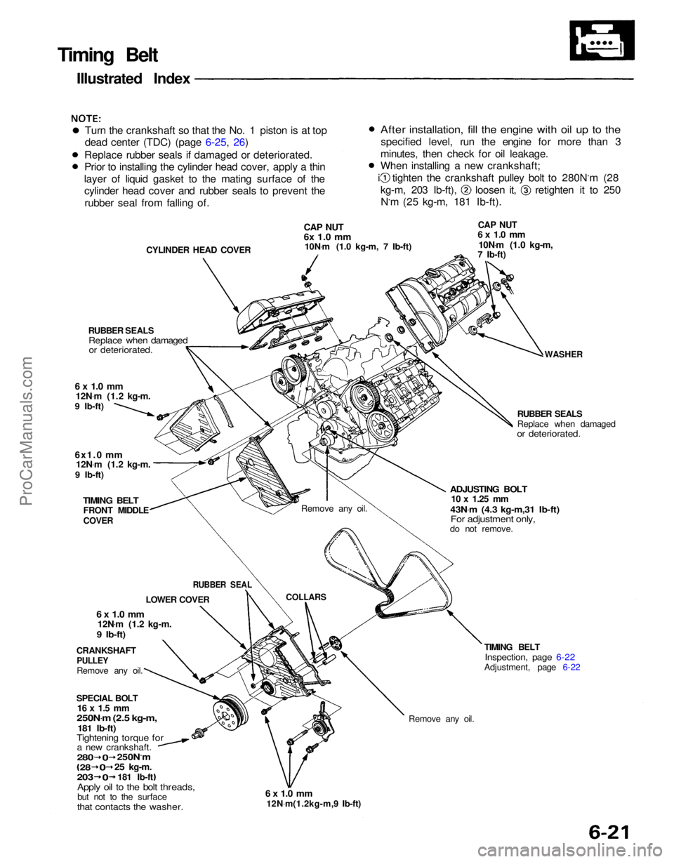
Timing Belt
Illustrated Index
Turn the crankshaft so that the No. 1 piston is at top
dead center (TDC) (page 6-25, 26)
Replace rubber seals if damaged or deteriorated.
Prior to installing the cylinder head cover, apply a thin
layer of liquid gasket to the mating surface of the cylinder head cover and rubber seals to prevent the
rubber seal from falling of.
CYLINDER HEAD COVER
CAP NUT
6x 1.0 mm
10N .
m (1.0 kg-m, 7 Ib-ft)
CAP NUT
6 x 1.0 mm
10N .
m (1.0 kg-m,
7 Ib-ft)
WASHER
RUBBER SEALS
Replace when damaged
or deteriorated.
ADJUSTING BOLT
10 x
1.25
mm
43N .
m (4.3 kg-m,31 Ib-ft)
For adjustment only,
do not remove.
Remove any oil.
COLLARS
RUBBER SEALS
Replace when damaged
or deteriorated.
6 x 1.0 mm
12N .
m (1.2 kg-m.
9 Ib-ft)
6x1.0
mm
12N .
m (1.2 kg-m.
9 Ib-ft)
TIMING BELT
FRONT MIDDLE
COVER
CRANKSHAFT
PULLEY
Remove any oil.
6 x 1.0 mm
12N .
m (1.2 kg-m.
9 Ib-ft)
SPECIAL BOLT
16 x 1.5 mm
250N .
m (2.5 kg-m,
181 Ib-ft)
Tightening torque for
a new crankshaft.
Apply oil to the bolt threads,
but not to the surface
that contacts the washer.
280
0
250N.m
28
0
25
kg-m.
203
0
181 Ib-ft LOWER COVER
RUBBER SEAL
After installation, fill the engine with oil up to the
specified level, run the engine for more than 3
minutes, then check for oil leakage.
When installing a new crankshaft; i tighten the crankshaft pulley bolt to 280N.m (28
kg-m, 203 Ib-ft), loosen it, retighten it to 250
N.m (25 kg-m, 181 Ib-ft).ProCarManuals.com
Page 1008 of 1640
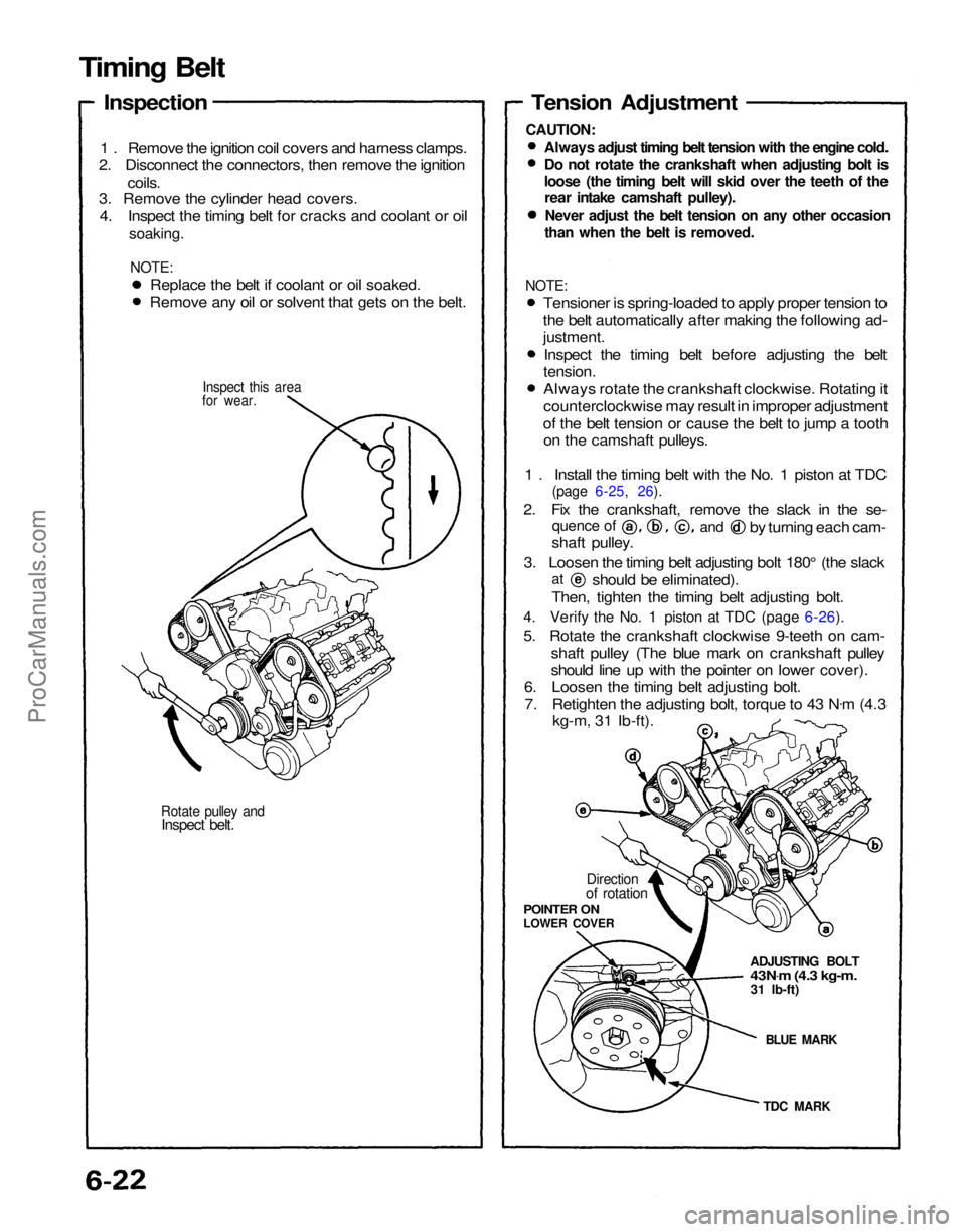
Rotate pulley and
Inspect belt.
for wear.
1 . Remove the ignition coil covers and harness clamps.
2. Disconnect the connectors, then remove the ignition
coils.
3. Remove the cylinder head covers.
4. Inspect the timing belt for cracks and coolant or oil
soaking.
NOTE:
TDC MARK
BLUE MARK
ADJUSTING BOLT
43N
.
m (4.3 kg-m.
31 Ib-ft)
Direction
of rotation
POINTER ON
LOWER COVER
Tension Adjustment
Always adjust timing belt tension with the engine cold.
Do not rotate the crankshaft when adjusting bolt is
loose (the timing belt will skid over the teeth of the
rear intake camshaft pulley).
Never adjust the belt tension on any other occasion
than when the belt is removed.
shaft pulley.
3. Loosen the timing belt adjusting bolt 180° (the slack
Then, tighten the timing belt adjusting bolt.
4. Verify the No. 1 piston at TDC (page 6-26).
5. Rotate the crankshaft clockwise 9-teeth on cam- shaft pulley (The blue mark on crankshaft pulley
should line up with the pointer on lower cover).
6. Loosen the timing belt adjusting bolt.
7. Retighten the adjusting bolt, torque to 43 N .
m (4.3
kg-m, 31 Ib-ft).
at
should be eliminated).
quence of
and
by turning each cam-
Replace the belt if coolant or oil soaked.
Remove any oil or solvent that gets on the belt.
Inspect this area
Timing Belt
Inspection
CAUTION:
NOTE:
Tensioner is spring-loaded to apply proper tension to
the belt automatically after making the following ad-
justment.
Inspect the timing belt before adjusting the belt
tension.
Always rotate the crankshaft clockwise. Rotating it
counterclockwise may result in improper adjustment
of the belt tension or cause the belt to jump a tooth on the camshaft pulleys.
1 . Install the timing belt with the No. 1 piston at TDC
(page 6-25, 26).
2. Fix the crankshaft, remove the slack in the se-ProCarManuals.com
Page 1024 of 1640
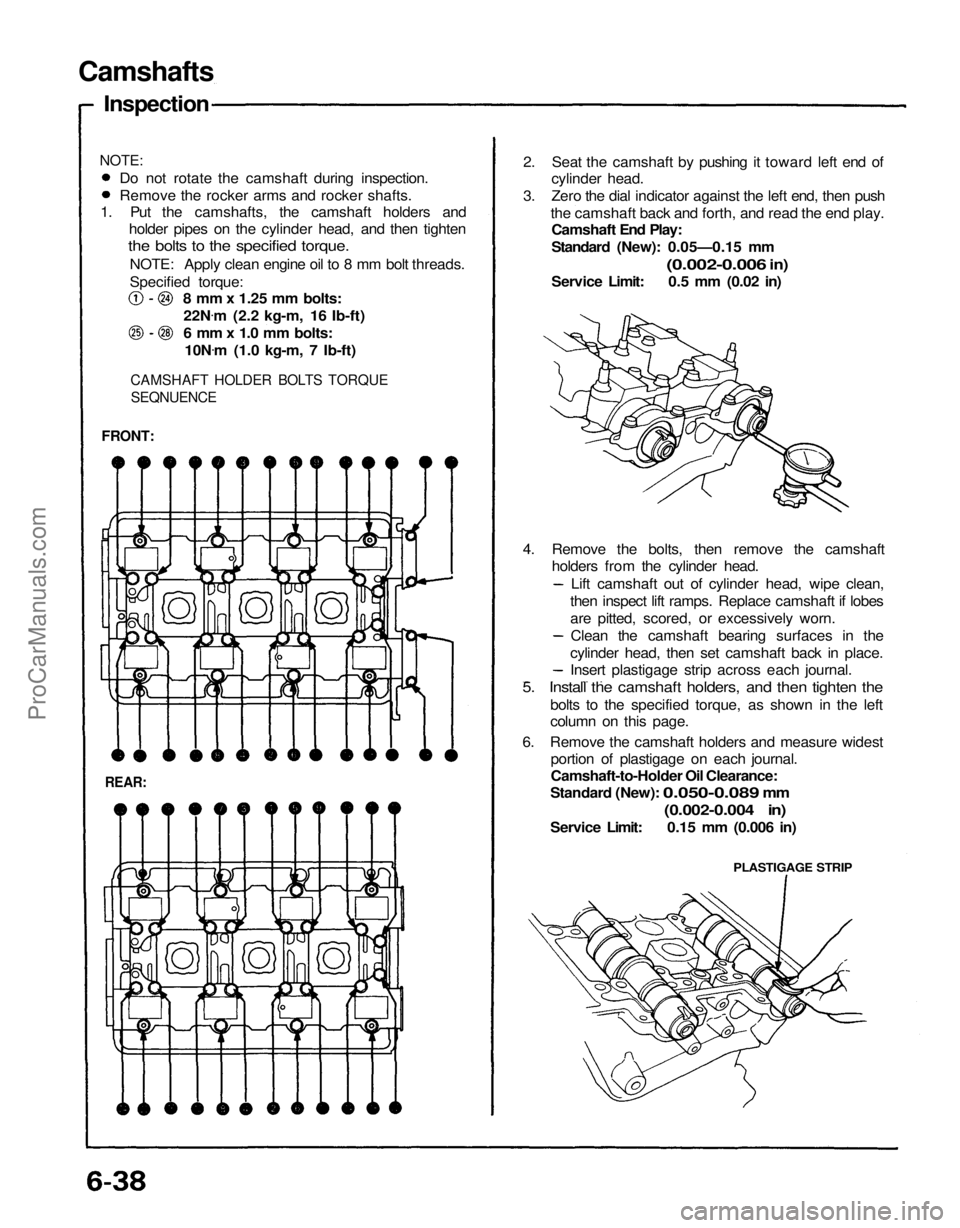
Camshafts
Inspection
1. Put the camshafts, the camshaft holders and holder pipes on the cylinder head, and then tighten
the bolts to the specified torque.
NOTE: Apply clean engine oil to 8 mm bolt threads.
Specified torque: 8 mm x 1.25 mm bolts:
22N .
m (2.2 kg-m, 16 Ib-ft)
6 mm x 1.0 mm bolts: 10N .
m (1.0 kg-m, 7 Ib-ft)
CAMSHAFT HOLDER BOLTS TORQUE
SEQNUENCE
FRONT:
REAR:
PLASTIGAGE STRIP
2. Seat the camshaft by pushing it toward left end of
cylinder head.
3. Zero the dial indicator against the left end, then push the camshaft back and forth, and read the end play.Camshaft End Play:
Standard (New): 0.05—0.15 mm
(0.002-0.006
in)
Service Limit: 0.5 mm (0.02 in)
4. Remove the bolts, then remove the camshaft holders from the cylinder head.
Do not rotate the camshaft during inspection.
Remove the rocker arms and rocker shafts.
NOTE:
Lift camshaft out of cylinder head, wipe clean,
then inspect lift ramps. Replace camshaft if lobes
are pitted, scored, or excessively worn. Clean the camshaft bearing surfaces in the
cylinder head, then set camshaft back in place.
Insert plastigage strip across each journal.
5. Install the camshaft holders, and then tighten the
bolts to the specified torque, as shown in the left
column on this page.
6. Remove the camshaft holders and measure widest portion of plastigage on each journal.
Camshaft-to-Holder Oil Clearance:
Standard (New):
0.050-0.089
mm
(0.002-0.004 in)
Service Limit: 0.15 mm (0.006 in)ProCarManuals.com
Page 1036 of 1640
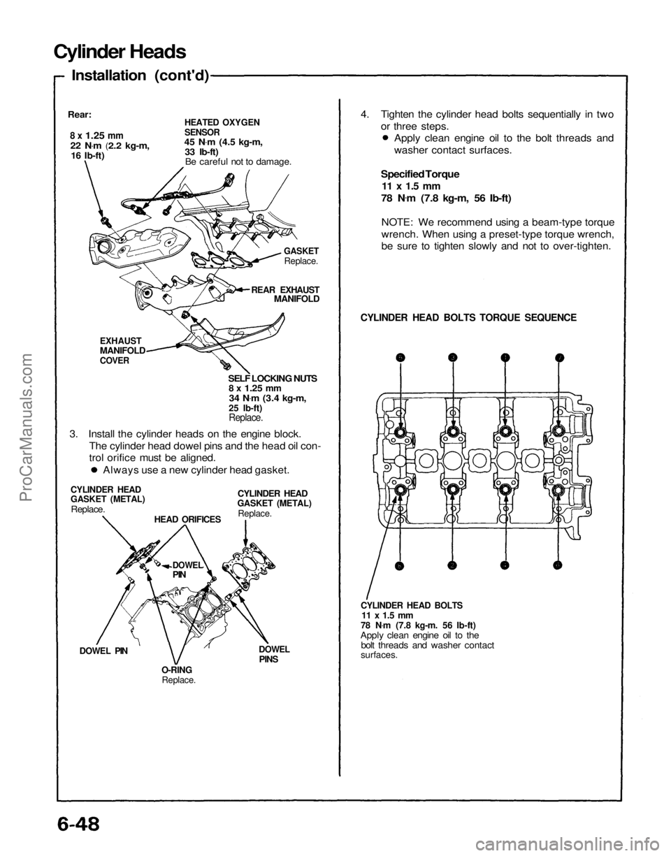
Cylinder Heads
Installation (cont'd)
Rear:
8 x
1.25
mm
22 N .
m
(2.2 kg-m,
16 Ib-ft)
HEATED OXYGEN
SENSOR
45 N .
m
(4.5 kg-m,
33 Ib-ft) Be careful not to damage.
GASKET
Replace.
REAR EXHAUST
MANIFOLD
EXHAUST
MANIFOLD
COVER
SELF LOCKING NUTS
8 x
1.25
mm
34 N .
m
(3.4 kg-m,
25 Ib-ft)
Replace.
3. Install the cylinder heads on the engine block. The cylinder head dowel pins and the head oil con-
trol orifice must be aligned.
CYLINDER HEAD
GASKET (METAL)
Replace.
CYLINDER HEAD
GASKET (METAL)
Replace.
HEAD ORIFICES
DOWEL
PIN
DOWEL PIN
O-RING
Replace.
DOWEL
PINS
CYLINDER HEAD BOLTS
11 x 1.5 mm
78 N .
m (7.8 kg-m. 56 Ib-ft)
Apply clean engine oil to the bolt threads and washer contact
surfaces.
CYLINDER HEAD BOLTS TORQUE SEQUENCE
Specified Torque
11 x 1.5 mm
78 N .
m (7.8 kg-m, 56 Ib-ft)
NOTE: We recommend using a beam-type torque
wrench. When using a preset-type torque wrench,
be sure to tighten slowly and not to over-tighten.
Always use a new cylinder head gasket. Apply clean engine oil to the bolt threads and
washer contact surfaces.
4. Tighten the cylinder head bolts sequentially in two
or three steps.ProCarManuals.com
Page 1038 of 1640
Camshafts
Installation (cont'd)
5. Apply liquid gasket to the head mating surfaces of the No. 1 and the No. 4 camshaft holders.Apply liquid gasket to the shaded areas.
6. Place the camshaft holders.
REAR:
No. 4 No. 3 No. 2 No. 1
CAMSHAFT CAMSHAFT CAMSHAFT CAMSHAFT
HOLDER HOLDER HOLDER HOLDER
REAR:
7. Place the cam holder pipes.
8. Tighten each bolt two turns at a time in the sequence
shown below to insure that the rockers do not bind
on the valves.
NOTE: Apply clean engine oil to 8 mm bolt threads.
Specified torque: 8 mm x 1.25 mm bolts:
22 N .
m (2.2 kg-m, 16 Ib-ft)
6 mm x 1.0 mm bolts:
10 N .
m (1.0 kg-m, 7 Ib-ft)
CAMSHAFT HOLDER BOLT TORQUE SEQUENCE
FRONT:
NOTE:
"F" or "R" marks are stamped on the camshaft
holders.
The arrows must be pointing to the timing belt
side.Set two dowel pins in each camshaft holder.
FRONT:
No. 4 No. 3 No. 2 No. 1
CAMSHAFT CAMSHAFT CAMSHAFT CAMSHAFT
HOLDER HOLDER HOLDER HOLDERProCarManuals.com