Page 373 of 1640
Preset Torque
Inspection
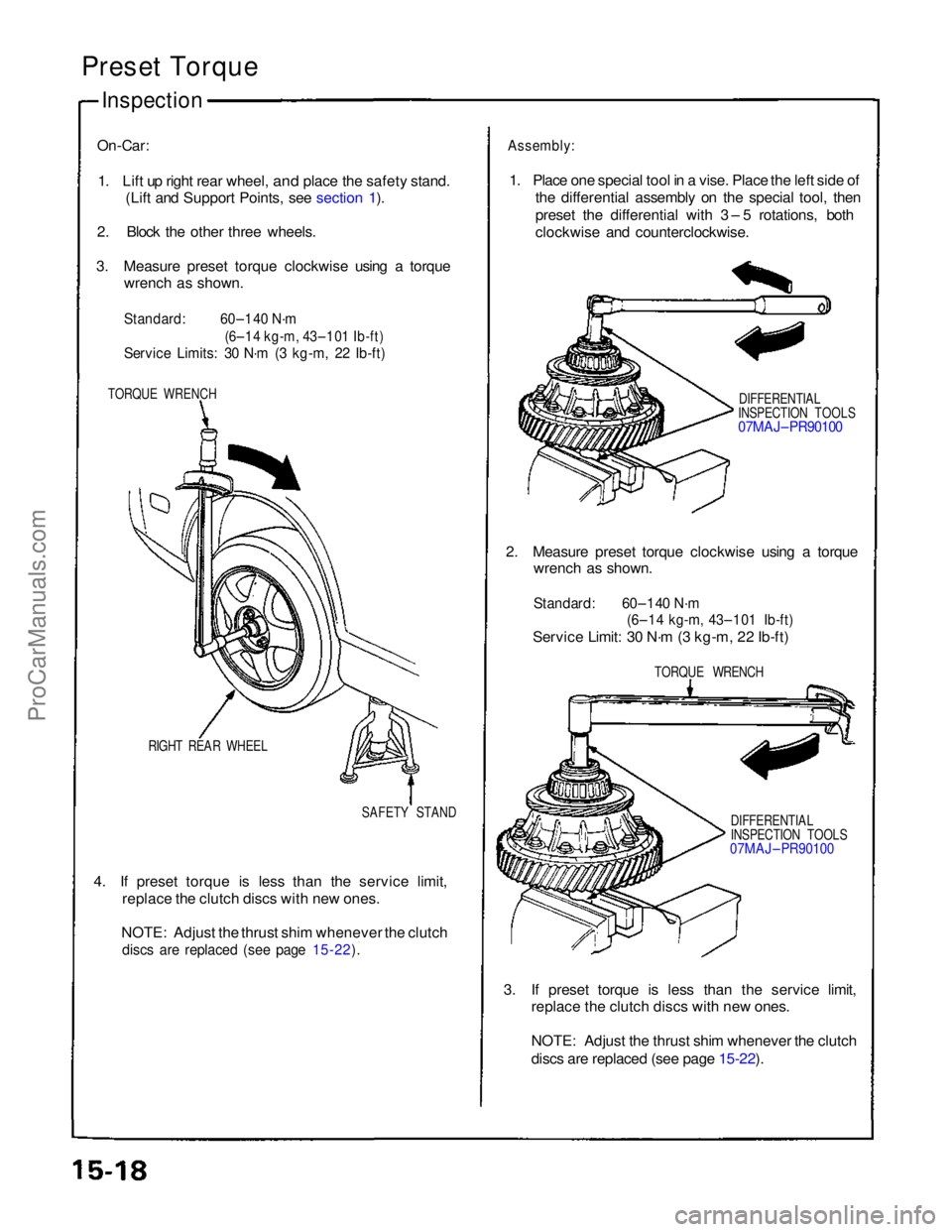
On-Car:
1. Lift up right rear wheel,
and place the safety stand.
(Lift and Support Points, see section 1).
2. Block the other three wheels.
3. Measure preset torque clockwise using a torque wrench as shown.
Standard:
60–140 N·m
(6–14 kg-m, 43–101 Ib-ft)
Service Limits: 30 N·m (3 kg-m, 22 Ib-ft)
TORQUE WRENCH
RIGHT REAR WHEEL SAFETY STAND
4. If preset torque is less than the service limit, replace the clutch discs with new ones.
NOTE: Adjust the thrust shim whenever the clutch
discs are replaced (see page 15-22).
Assembly:
1. Place one special tool in a vise. Place the left side of the differential assembly on the special tool, then
preset the differential with 3 – 5 rotations, both
clockwise and counterclockwise.
DIFFERENTIAL
INSPECTION TOOLS
07MAJ– PR90100
2. Measure preset torque clockwise using a torque wrench as shown.
Standard: 60–140 N·m
(6–14 kg-m, 43–101 Ib-ft)
Service Limit: 30 N·m (3 kg-m, 22 Ib-ft)
TORQUE WRENCH
DIFFERENTIAL
INSPECTION TOOLS
07MAJ – PR90100
3. If preset torque is less than the service limit, replace the clutch discs with new ones.
NOTE: Adjust the thrust shim whenever the clutch
discs are replaced (see page 15-22).
ProCarManuals.com
Page 377 of 1640
\
I
Clutch Disc, Clutch Plate
Replacement
NOTE: The clutch discs and clutch plates should be
replaced as a set.
1. Remove the clutch discs and clutch plates (see
page15-20).
2. Soak the clutch discs for five minutes in transmis-
sion oil.
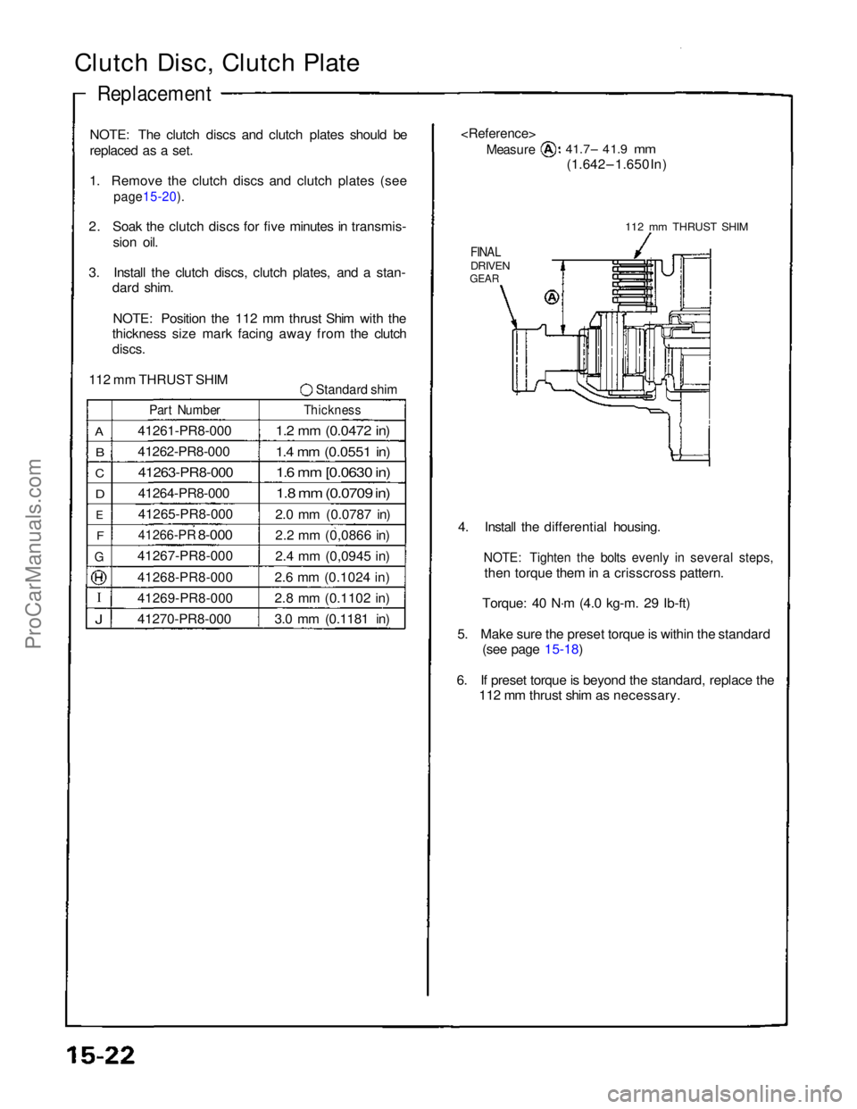
3. Install the clutch discs, clutch plates, and a stan- dard shim.
NOTE: Position the 112 mm thrust Shim with the
thickness size mark facing away from the clutch
discs.
112 mm THRUST SHIM
Standard shim
A
B
C
D
E
F
G
J
Part Number
41261-PR8-000
41262-PR8-000
41263-PR8-000
41264-PR8-000
41265-PR8-000
41266-PR
8-000
41267-PR8-000
41268-PR8-000
41269-PR8-000
41270-PR8-000
Thickness
1.2 mm (0.0472 in)
1.4 mm (0.0551 in)
1.6 mm [0.0630 in)
1.8 mm (0.0709 in)
2.0 mm (0.0787 in)
2.2 mm (0,0866 in)
2.4 mm (0,0945 in)
2.6 mm (0.1024 in)
2.8 mm (0.1102 in)
3.0 mm (0.1181 in)
Measure
41.7– 41.9
mm
(1.642 – 1.650 In)
112 mm THRUST SHIM
FINAL
DRIVEN
GEAR
4. Install the differential housing.
NOTE: Tighten the bolts evenly in several steps,
then torque them in a crisscross pattern.
Torque: 40 N·m (4.0 kg-m. 29 Ib-ft)
5. Make sure the preset torque is within the standard (see page 15-18)
6. If preset torque is beyond the standard, replace the 112 mm thrust shim as necessary.ProCarManuals.com
Page 381 of 1640
Oil Seal
Removal
1. Remove the differential assembly.
2. Remove the oil seal from the transmission housing.
OIL SEAL
Replace.
TRANSMISSION
HOUSING
3. Remove the oil seal from the torque converter
housing.
OIL SEAL
Replace.
TORQUE CONVERTER
HOUSINGProCarManuals.com
Page 382 of 1640
Bearing Preload
Adjustment
NOTE: If any of the items listed below are replaced, the
bearing preload must be adjusted.
TRANSMISSION HOUSING
TORQUE CONVERTER HOUSING
DIFFERENTIAL
TAPERED ROLLER BEARING and OUTER RACE
75 mm THRUST SHIM
90 mm WASHER
OIL GUIDE RING
1. Remove the bearing outer race and 75 mm thrust
shim from the transmission housing by prying up
on the bearing outer race or by heating the housing
to about 212°F (100°C).
CAUTION: Do not reuse the thrust shim if the
outer race was pried out.
NOTE:
• If the outer race was removed by heating the
case, let the transmission cool to room tempera-
ture before adjusting the bearing preload.
• Do not heat the transmission housing in excess
of 212°F (100°C).
• Replace the bearing with a new one whenever
the outer race is replaced.
• Repeat on the torque converter side.ProCarManuals.com
Page 383 of 1640
2. Instal l th e standar d shi m an d bearin g oute r rac e in -
t o th e transmissio n housin g usin g th e specia l tool s
a s shown .
CAUTION : D o no t us e mor e tha n on e shi m to ad -
jus t th e bearin g preload .
NOTE:
• Instal l th e bearin g oute r rac e squarely .
• Chec k tha t ther e i s n o clearanc e betwee n th e
bearin g oute r race , shim , an d transmissio n
housing .
DRIVER07749-0010000 ATTACHMEN T72 x 7 5 m m07746-0010600
BEARIN GOUTERRACE
75 m m THRUS TSHIM
3. Lubricat e th e tapere d rolle r bearin g wit h transmis -
sio n fluid , the n instal l th e differential .
4 . Instal l th e transmissio n housing .
NOTE : D o no t instal l th e mainshaft , countershaft ,
revers e idl e gea r shaft , an d secondar y shaft .
Torque : 5 5 N- m (5. 5 kg-m , 4 0 Ib-ft )
5. Rotat e th e differentia l assembl y i n bot h direction s
t o sea t th e bearings .
7
5 m m THRUS T SHIM :
ProCarManuals.com
Page 408 of 1640
System Description
Major Components
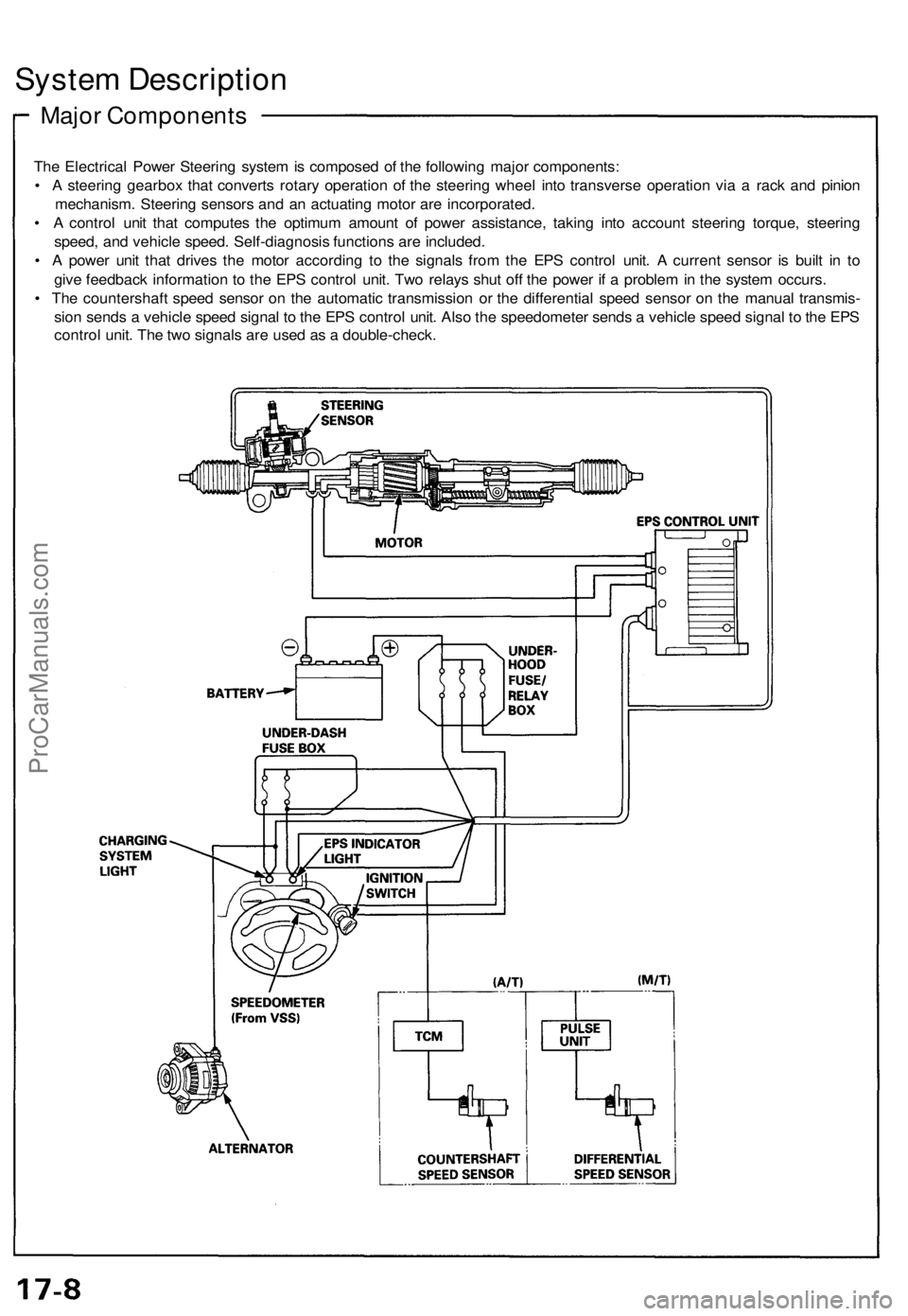
The Electrical Power Steering system is composed of the following major components:
• A steering gearbox that converts rotary operation of the steering wheel into transverse operation via a rack and pinion
mechanism. Steering sensors and an actuating motor are incorporated.
• A control unit that computes the optimum amount of power assistance, taking into account steering torque, steering
speed, and vehicle speed. Self-diagnosis functions are included.
• A power unit that drives the motor according to the signals from the EPS control unit. A current sensor is built in to
give feedback information to the EPS control unit. Two relays shut off the power if a problem in the system occurs.
• The countershaft speed sensor on the automatic transmission or the differential speed sensor on the manual transmis-
sion sends a vehicle speed signal to the EPS control unit. Also the speedometer sends a vehicle speed signal to the EPS
control unit. The two signals are used as a double-check.ProCarManuals.com
Page 409 of 1640
System Operation
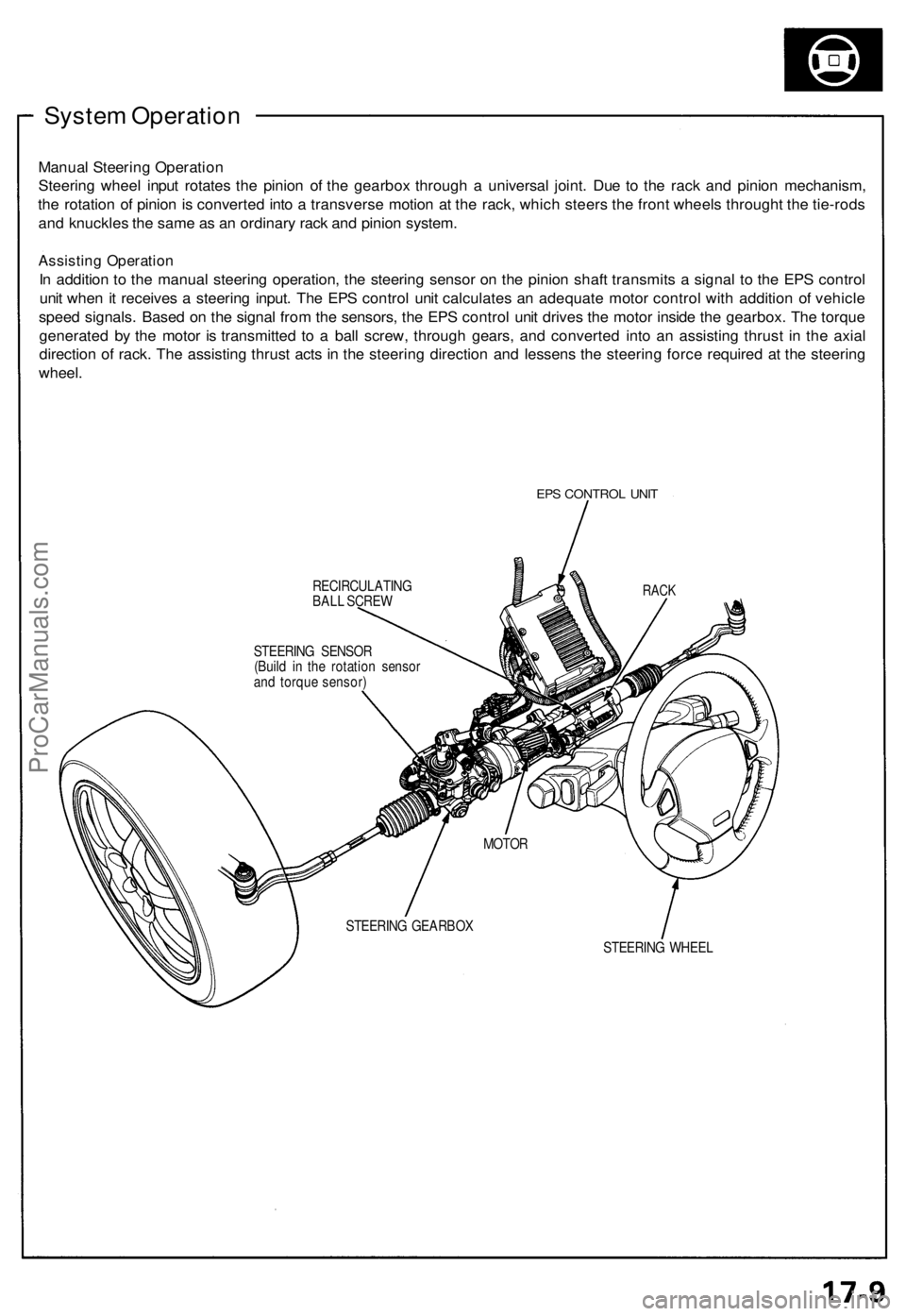
Manual Steering Operation
Steering wheel input rotates the pinion of the gearbox through a universal joint. Due to the rack and pinion mechanism,
the rotation of pinion is converted into a transverse motion at the rack, which steers the front wheels throught the tie-rods
and knuckles the same as an ordinary rack and pinion system.
Assisting Operation
In addition to the manual steering operation, the steering sensor on the pinion shaft transmits a signal to the EPS control
unit when it receives a steering input. The EPS control unit calculates an adequate motor control with addition of vehicle
speed signals. Based on the signal from the sensors, the EPS control unit drives the motor inside the gearbox. The torque
generated by the motor is transmitted to a ball screw, through gears, and converted into an assisting thrust in the axial
direction of rack. The assisting thrust acts in the steering direction and lessens the steering force required at the steering
wheel.
EPS CONTROL UNIT
RECIRCULATING
BALL SCREW
STEERING WHEEL
RACK
STEERING SENSOR
(Build in the rotation sensor
and torque sensor)
MOTOR
STEERING GEARBOXProCarManuals.com
Page 410 of 1640
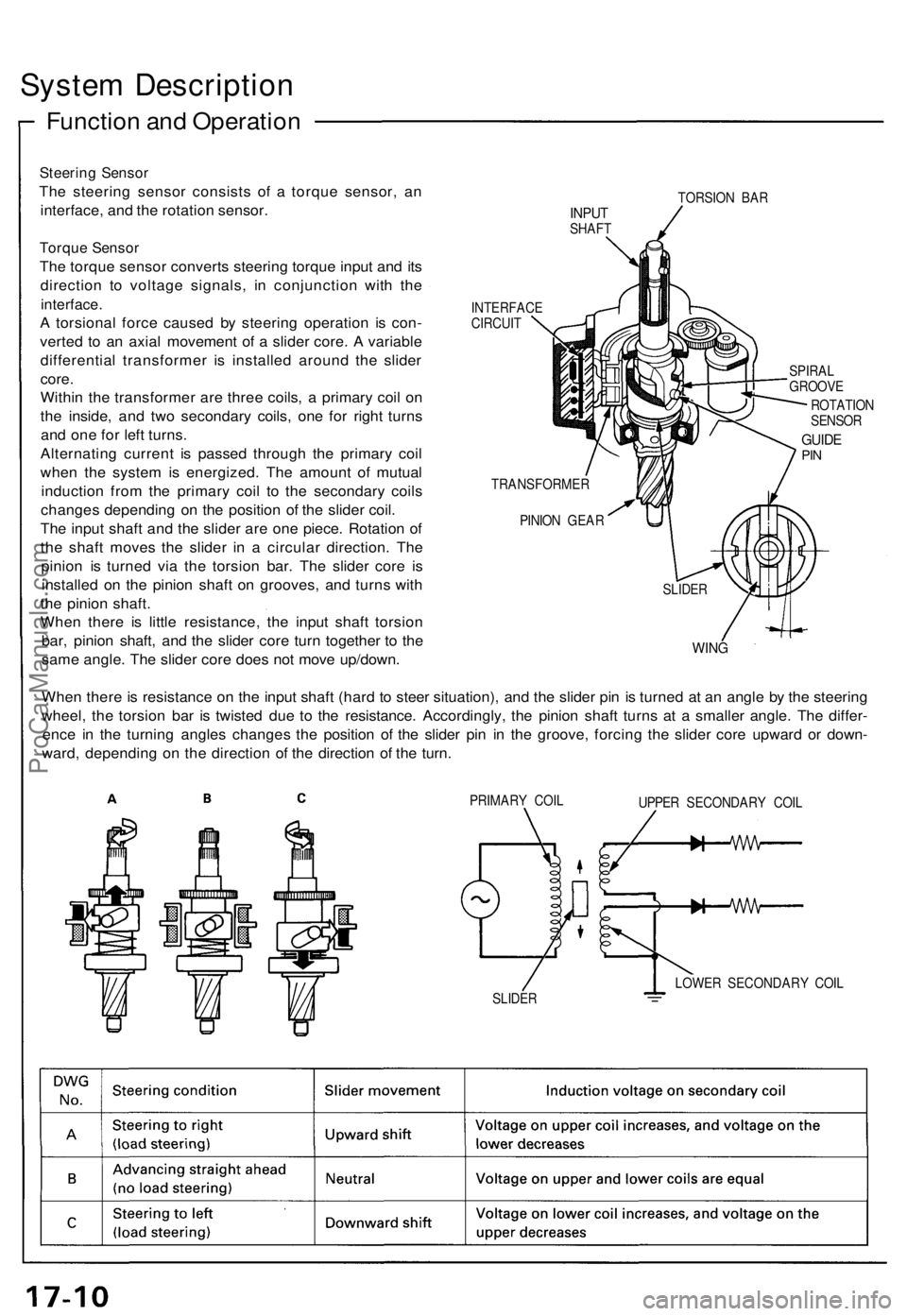
System Description
Function and Operation
Steering Sensor
The steering sensor consists of a torque sensor, an
interface, and the rotation sensor.
Torque Sensor
The torque sensor converts steering torque input and its
direction to voltage signals, in conjunction with the
interface.
A torsional force caused by steering operation is con-
verted to an axial movement of a slider core. A variable
differential transformer is installed around the slider
core.
Within the transformer are three coils, a primary coil on
the inside, and two secondary coils, one for right turns
and one for left turns.
Alternating current is passed through the primary coil
when the system is energized. The amount of mutual
induction from the primary coil to the secondary coils
changes depending on the position of the slider coil.
The input shaft and the slider are one piece. Rotation of
the shaft moves the slider in a circular direction. The
pinion is turned via the torsion bar. The slider core is
installed on the pinion shaft on grooves, and turns with
the pinion shaft.
When there is little resistance, the input shaft torsion
bar, pinion shaft, and the slider core turn together to the
same angle. The slider core does not move up/down.
TORSION BAR
INPUT
SHAFT
INTERFACE
CIRCUIT
SPIRAL
GROOVE
ROTATION
SENSOR
GUIDE
PIN
TRANSFORMER
PINION GEAR
WING
When there is resistance on the input shaft (hard to steer situation), and the slider pin is turned at an angle by the steering
wheel, the torsion bar is twisted due to the resistance. Accordingly, the pinion shaft turns at a smaller angle. The differ-
ence in the turning angles changes the position of the slider pin in the groove, forcing the slider core upward or down-
ward, depending on the direction of the direction of the turn.
PRIMARY COIL
UPPER SECONDARY COIL
LOWER SECONDARY COIL
SLIDER
SLIDERProCarManuals.com