Page 490 of 1640
6. Install the new self-locking nuts on the top of the
damper assembly.
7. Tighten the damper mounting nut to the specified
torque.
8. Secure the damper assembly to the frame with the
self-locking nuts.
9. Install the strut brace.
10. Install the rear hatch glass trim.
11. Install the engine cover support rod onto the strut
brace.
12. Install the rear wheels.ProCarManuals.com
Page 492 of 1640
Illustrated Index
The accumulator contains high-pressure nitrogen gas; do not puncture, expose to flame or attempt to
disassemble the accumulator or it may explode; severe personal injury may result.
HYDRAULIC SYSTEM
Relieving Accumulator/line pressure, page 19-62 ('91-'92) ('93-'96)
MASTER CYLINDER
Index/Torque, page 19-12
Inspection, page 19-13
ABS CONTROL UNIT Replacement, page 19-70
BRAKE BOOSTER
Tests, page 19-14 Pushrod clearance adjustment, page 19-15
UNDER-HOOD
RELAY BOX B
UNDER-HOOD
FUSE/RELAY BOX
REAR WHEEL SENSOR
Inspection, page 19-71
Replacement, page 19-72
POWER UNIT
Torque/Inspection, page 19-66
ACCUMULATOR/PRESSURE SWITCHIndex/Torque, page 19-67 FRONT WHEEL SENSOR
Inspection, page 19-71
Replacement, page 19-72
MODULATOR/SOLENOID UNIT
Index/Torque, page 19-63 ('91-'92) ('93-'96)
Solenoid Leak Test, page 19-64 ('91-'92) ('93-'96)
ProCarManuals.com
Page 496 of 1640
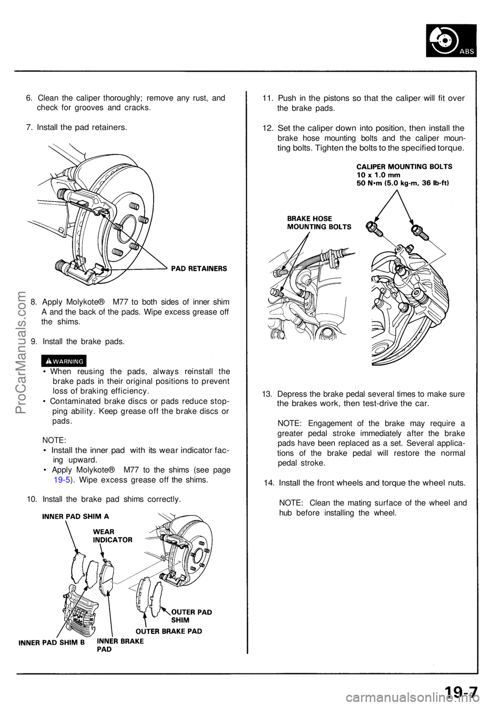
6. Clea n th e calipe r thoroughly ; remov e an y rust , an d
chec k fo r groove s an d cracks .
7. Instal l th e pa d retainers .
11. Pus h i n th e piston s s o tha t th e calipe r wil l fi t ove r
the brak e pads .
12. Se t th e calipe r dow n int o position , the n instal l th e
brak e hos e mountin g bolt s an d th e calipe r moun -
ting bolts . Tighte n th e bolt s to th e specifie d torque .
8. Appl y Molykote ® M7 7 t o bot h side s o f inne r shi m
A an d th e bac k o f th e pads . Wip e exces s greas e of f
th e shims .
9 . Instal l th e brak e pads .
• Whe n reusin g th e pads , alway s reinstal l th e
brak e pad s i n thei r origina l position s t o preven t
los s o f brakin g efficiency .
• Contaminate d brak e disc s o r pad s reduc e stop -
pin g ability . Kee p greas e of f th e brak e disc s o r
pads .
NOTE :
• Instal l th e inne r pa d wit h it s wea r indicato r fac -
ing upward .
• Appl y Molykote ® M7 7 t o th e shim s (se e pag e
19-5 ). Wip e exces s greas e of f th e shims .
10 . Instal l th e brak e pa d shim s correctly . 13
. Depres s th e brak e peda l severa l time s t o mak e sur e
the brake s work , the n test-driv e th e car .
NOTE : Engagemen t of the brak e ma y requir e a
greate r peda l strok e immediatel y afte r th e brak e
pad s hav e bee n replace d a s a set . Severa l applica -
tion s of the brak e peda l wil l restor e th e norma l
peda l stroke .
14. Instal l th e fron t wheel s an d torqu e th e whee l nuts .
NOTE : Clea n th e matin g surfac e o f th e whee l an d
hu b befor e installin g th e wheel .
ProCarManuals.com
Page 503 of 1640
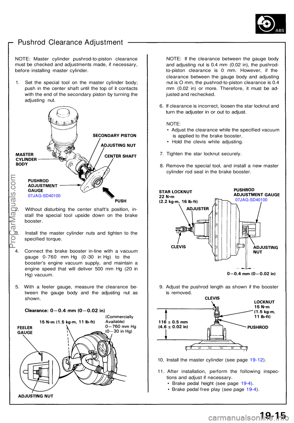
Pushrod Clearanc e Adjustmen t
NOTE: Maste r cylinde r pushrod-to-pisto n clearanc e
mus t b e checke d an d adjustment s made , i f necessary ,
befor e installin g maste r cylinder .
1 . Se t th e specia l too l o n th e maste r cylinde r body ;
pus h i n th e cente r shaf t unti l th e to p o f i t contact s
wit h th e en d o f th e secondar y pisto n b y turnin g th e
adjustin g nut .
07JAG-SD4010 0
2. Withou t disturbin g th e cente r shaft' s position , in -
stal l th e specia l too l upsid e dow n o n th e brak e
booster .
3 . Instal l th e maste r cylinde r nut s an d tighte n t o th e
specifie d torque .
4 . Connec t th e brak e booste r in-lin e wit h a vacuu m
gaug e 0-76 0 m m H g ( 0 -3 0 i n Hg ) t o th e
booster' s engin e vacuu m supply , an d maintai n a
engin e spee d tha t wil l delive r 50 0 m m H g (2 0 i n
Hg ) vacuum .
5 . Wit h a feele r gauge , measur e th e clearanc e be -
twee n th e gaug e bod y an d th e adjustin g nu t a s
shown . NOTE
: I f th e clearanc e betwee n th e gaug e bod y
an d adjustin g nu t i s 0. 4 m m (0.0 2 in) , th e pushrod -
to-pisto n clearanc e i s 0 mm . However , i f th e
clearanc e betwee n th e gaug e bod y an d adjustin g
nu t i s O mm , th e pushrod-to-pisto n clearanc e is 0. 4
m m (0.0 2 in ) o r more . Therefore , i t mus t b e ad -
juste d an d rechecked .
6 . I f clearanc e is incorrect , loose n th e sta r locknu t an d
turn th e adjuste r i n o r ou t t o adjust .
NOTE:
• Adjus t th e clearanc e whil e th e specifie d vacuu m
i s applie d t o th e brak e booster .
• Hol d th e clevi s whil e adjusting .
7 . Tighte n th e sta r locknu t securely .
8 . Remov e th e specia l tool , an d instal l a ne w maste r
cylinde r ro d sea l i n th e brak e booster .
07JAG-SD40100
9. Adjus t th e pushro d lengt h a s show n i f th e booste r
i s removed .
10 . Instal l th e maste r cylinde r (se e pag e 19-12 ).
11 . Afte r installation , perfor m th e followin g inspec -
tion s an d adjus t i f necessary .
• Brak e peda l heigh t (se e pag e 19-4 ).
• Brak e peda l fre e pla y (se e pag e 19-4 ).
ProCarManuals.com
Page 504 of 1640
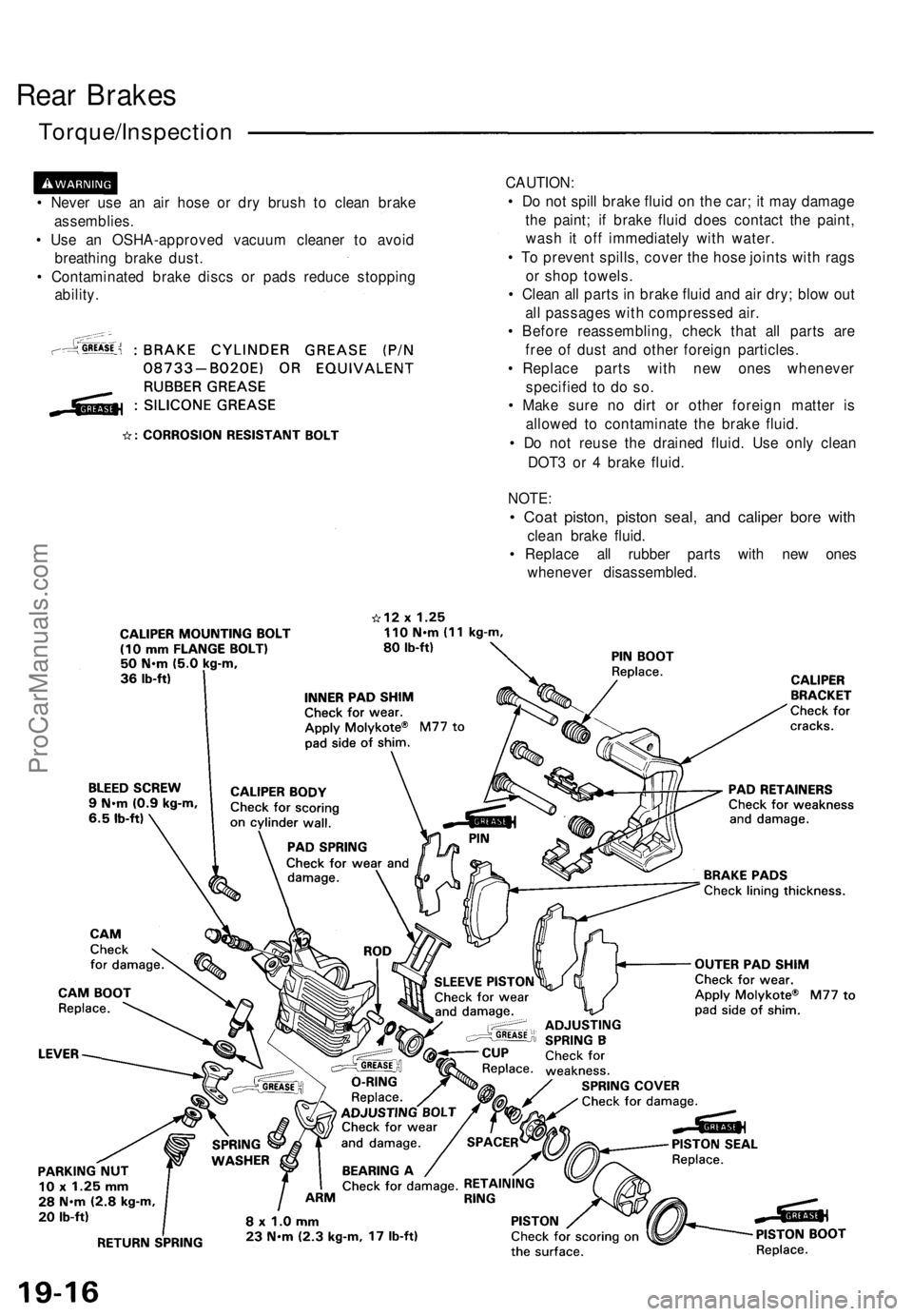
Rear Brakes
Torque/Inspection
• Never use an air hose or dry brush to clean brake
assemblies.
• Use an OSHA-approved vacuum cleaner to avoid
breathing brake dust.
• Contaminated brake discs or pads reduce stopping
ability.
CAUTION:
• Do not spill brake fluid on the car; it may damage
the paint; if brake fluid does contact the paint,
wash it off immediately with water.
• To prevent spills, cover the hose joints with rags
or shop towels.
• Clean all parts in brake fluid and air dry; blow out
all passages with compressed air.
• Before reassembling, check that all parts are
free of dust and other foreign particles.
• Replace parts with new ones whenever
specified to do so.
• Make sure no dirt or other foreign matter is
allowed to contaminate the brake fluid.
• Do not reuse the drained fluid. Use only clean
DOT3 or 4 brake fluid.
NOTE:
• Coat piston, piston seal, and caliper bore with
clean brake fluid.
• Replace all rubber parts with new ones
whenever disassembled.ProCarManuals.com
Page 507 of 1640
11. Install and tighten the two caliper mounting bolts.
12. Insert the cable through the arm, and connect the
cable to the lever with the clevis pin and new lock
pin.
Install the new cable clip securely.
13. Install the caliper shield.
14. Depress the brake pedal several times to make sure
the brakes work, then test-drive the car.
NOTE: Engagement of the brake may require a
greater pedal stroke immediately after the brake
pads have been replaced as a set. Several applica-
tions of the brake pedal will restore the normal
pedal stroke.
1 5. Install the rear wheels and torque the wheel nuts.
NOTE: Clean the mating surfaces of the wheel and
hub before installing the wheel.ProCarManuals.com
Page 538 of 1640
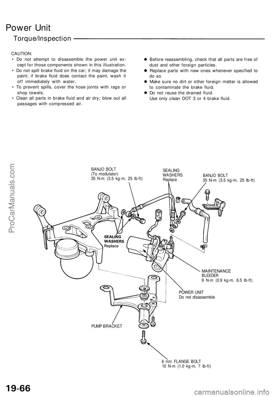
Power Uni t
Torque/Inspectio n
CAUTION:
• D o no t attemp t t o disassembl e th e powe r uni t ex -
cep t fo r thos e component s show n in thi s illustration .
• D o no t spil l brak e flui d o n th e car ; i t ma y damag e th e
paint ; i f brak e flui d doe s contac t th e paint , was h i t
of f immediatel y wit h water .
• T o preven t spills , cove r th e hos e joint s wit h rag s o r
sho p towels .
• Clea n al l part s i n brak e flui d an d ai r dry ; blo w ou t al l
passage s wit h compresse d air . Befor
e reassembling , chec k tha t al l part s ar e fre e o f
dus t an d othe r foreig n particles .
Replac e part s wit h ne w one s wheneve r specifie d t o
do so .
Mak e sur e n o dir t o r othe r foreig n matte r i s allowe d
t o contaminat e th e brak e fluid .
D o no t reus e th e draine d fluid .
Us e onl y clea n DO T 3 o r 4 brak e fluid .
BANJ O BOL T(To modulator )35 N- m (3. 5 kg-m , 2 5 Ib-ft )
SEALIN GWASHER SReplaceBANJO BOL T35 N- m (3. 5 kg-m , 2 5 Ib-ft )
MAINTENANC EBLEEDER9 N- m (0. 9 kg-m , 6. 5 Ib-ft )
POWE R UNI TDo no t disassembl e
PUMP BRACKE T
6 m m FLANG E BOL T10 N- m (1. 0 kg-m , 7 Ib-ft )
ProCarManuals.com
Page 539 of 1640
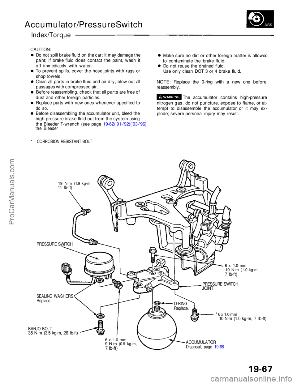
Accumulator/Pressure Switch
Index/Torque
CAUTION: Do not spill brake fluid on the car; it may damage the
paint; if brake fluid does contact the paint, wash it
off immediately with water.
To prevent spills, cover the hose jpints with rags or shop towels.
Clean all parts in brake fluid and air dry; blow out all passages with compressed air.
Before reassembling, check that all parts are free of
dust and other foreign particles. Replace parts with new ones whenever specified to
do so.
Before disassembling the accumulator unit, bleed the
high-pressure brake fluid out from the system using
the Bleeder T-wrench (see page 19-62('91-'92)('93-'96)
the Bleeder
*: CORROSION RESISTANT BOLT
Make sure no dirt or other foreign matter is allowed
to contaminate the brake fluid. Do not reuse the drained fluid.
Use only clean DOT 3 or 4 brake fluid.
NOTE: Replace the 0-ring with a new one before
reassembly. The accumulator contains high-pressure
nitrogen gas, do not puncture, expose to flame, or at-
tempt to disassemble the accumulator or it may ex-
plode; severe personal injury may result.
19 N·m
(1.9 kg-m,
14 Ib-ft)
PRESSURE SWITCH
SEALING WASHERS
Replace.
BANJO BOLT
35 N·m (3.5 kg-m, 26 Ib-ft)
6 x 1.0 mm
9 N·m
(0.9 kg-m,7 Ib-ft)
ACCUMULATOR
Disposal, page 19-68
* 6 x 1.0 mm
10 N·m (1.0 kg-m, 7 Ib-ft)
O-RING
Replace.
PRESSURE SWITCH
JOINT
6 x 1.0 mm
10 N·m
(1.0 kg-m,
7 Ib-ft)ProCarManuals.com