1991 ACURA NSX torque
[x] Cancel search: torquePage 411 of 1640
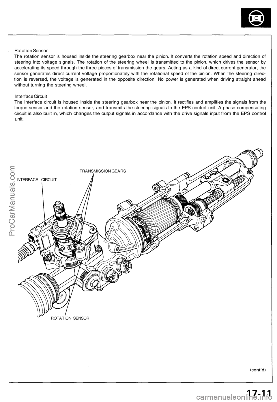
Rotation Sensor
The rotation sensor is housed inside the steering gearbox near the pinion. It converts the rotation speed and direction of
steering into voltage signals. The rotation of the steering wheel is transmitted to the pinion, which drives the sensor by
accelerating its speed through the three pieces of transmission the gears. Acting as a kind of direct current generator, the
sensor generates direct current voltage proportionately with the rotational speed of the pinion. When the steering direc-
tion is reversed, the voltage is generated in the opposite direction. No power is generated when driving straight ahead
without turning the steering wheel.
Interface Circuit
The interface circuit is housed inside the steering gearbox near the pinion. It rectifies and amplifies the signals from the
torque sensor and the rotation sensor, and transmits the steering signals to the EPS control unit. A phase compensating
circuit is also built in, which changes the output signals in accordance with the drive signals input from the EPS control
unit.
TRANSMISSION GEARS
INTERFACE CIRCUIT
ROTATION SENSORProCarManuals.com
Page 412 of 1640
System Description
Function and Operation
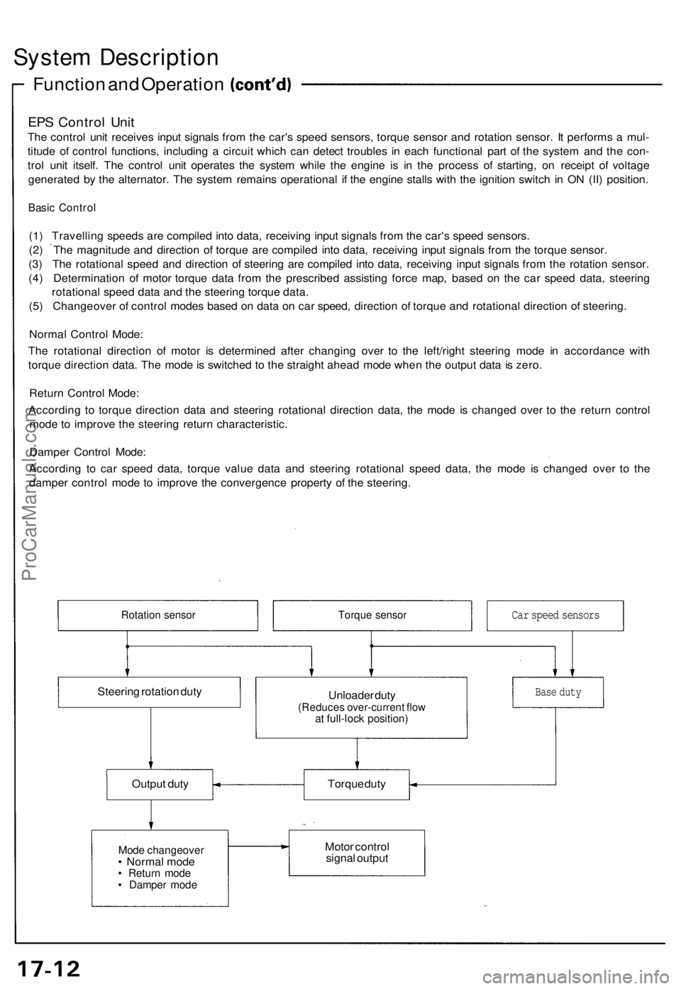
EPS Control Unit
The control unit receives input signals from the car's speed sensors, torque sensor and rotation sensor. It performs a mul-
titude of control functions, including a circuit which can detect troubles in each functional part of the system and the con-
trol unit itself. The control unit operates the system while the engine is in the process of starting, on receipt of voltage
generated by the alternator. The system remains operational if the engine stalls with the ignition switch in ON (II) position.
Basic Control
(1) Travelling speeds are compiled into data, receiving input signals from the car's speed sensors.
(2) The magnitude and direction of torque are compiled into data, receiving input signals from the torque sensor.
(3) The rotational speed and direction of steering are compiled into data, receiving input signals from the rotation sensor.
(4) Determination of motor torque data from the prescribed assisting force map, based on the car speed data, steering
rotational speed data and the steering torque data.
(5) Changeover of control modes based on data on car speed, direction of torque and rotational direction of steering.
Normal Control Mode:
The rotational direction of motor is determined after changing over to the left/right steering mode in accordance with
torque direction data. The mode is switched to the straight ahead mode when the output data is zero.
Return Control Mode:
According to torque direction data and steering rotational direction data, the mode is changed over to the return control
mode to improve the steering return characteristic.
Damper Control Mode:
According to car speed data, torque value data and steering rotational speed data, the mode is changed over to the
damper control mode to improve the convergence property of the steering.
Rotation sensor
Torque sensor
Steering rotation duty
Unloader duty
(Reduces over-current flow
at full-lock position)
Output duty
Torque duty
Mode changeover
• Normal mode
• Return mode
• Damper mode
Motor control
signal output
Base duty
Car speed sensorsProCarManuals.com
Page 414 of 1640
System Description
Function and Operation
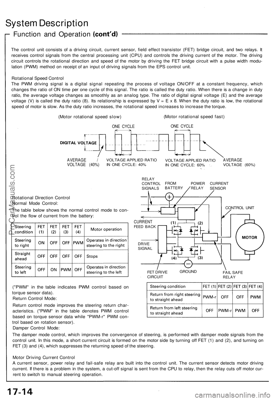
The control unit consists of a driving circuit, current sensor, field effect transistor (FET) bridge circuit, and two relays. It
receives control signals from the central processing unit (CPU) and controls the driving current of the motor. The driving
circuit controls the rotational direction and speed of the motor by driving the FET bridge circuit with a pulse width modu-
lation (PWM) method on receipt of an input of driving signals from the EPS control unit.
Rotational Speed Control
The PWM driving signal is a digital signal repeating the process of voltage ON/OFF at a constant frequency, which
changes the ratio of ON time per one cycle of this signal. The ratio is called the duty ratio. When there is a change in duty
ratio, the average voltage changes as smoothly as an analog type. The ratio of digital signal voltage (E) and the average
voltage (V) is called the duty ratio (8). Its relationship is expressed by V = E x 8. When the duty ratio is low, the rotational
speed of motor is slow. As the duty ratio increases, the rotational speed increases to increase the torque.
(Motor rotational speed slow)
ONE CYCLE
(Motor rotational speed fast)
ONE CYCLE
AVERAGE /
VOLTAGE (40%)
VOLTAGE APPLIED RATIO
IN ONE CYCLE: 40%
RELAY
CONTROL
SIGNALS
VOLTAGE APPLIED RATIO
IN ONE CYCLE: 60%
AVERAGE
VOLTAGE (60%)
FROM
BATTERY
POWER
RELAY
CURRENT
SENSOR
Rotational Direction Control
Normal Mode Control:
The table below shows the normal control mode to con-
trol the flow of current from the battery:
CURRENT
FEED BACK
DRIVE
SIGNAL
FET DRIVE
CIRCUIT
GROUND
FAIL SAFE
RELAY
("PWM" in the table indicates PWM control based on
torque sensor data).
Return Control Mode:
Return control mode improves the steering return char-
acteristics. ("PWM" in the table denotes PWM control
based on torque sensor data while "PWM-r" PWM con-
trol based on rotation sensor).
Damper Control Mode:
The damper mode control, which improves the convergence of steering, is performed with damper mode signals from the
control unit. In this mode, a short current circuit is formed on the motor side by turning off FET (1) and (2), and turning on
FET (3) and (4), which suppresses the returning speed of the steering.
Motor Driving Current Control
A current sensor, power relay and fail-safe relay are built into the control unit. The current sensor detects motor driving
current. If there is a problem in the system, a cut-off signal is sent from the CPU to relay, then the relay cuts off motor cur-
rent to switch to manual steering operation.
CONTROL UNITProCarManuals.com
Page 434 of 1640

Steering Colum n
Installatio n
SRS component s ar e locate d i n thi s area . Revie w th e
SR S componen t locations , precautions , an d procedure s
i n th e SR S sectio n 24 befor e performin g repair s o r ser -
vice .
1 . Sli p th e lowe r en d o f th e steerin g join t ont o th e pin -
io n shaft .
2 . Repositio n th e colum n assembl y o n th e hange r
bracket , an d loosel y tighte n wit h 8 m m flang e nuts .
COLUM N ASSEMBL Y
8 m m FLANG E NUT S16 N- m(1.6 kg-m , 1 2 Ib-ft )
3. Tighte n t o th e steerin g join t bolts .
NOTE :
• B e sur e tha t th e lowe r bol t i s securel y i n th e
groov e in th e steerin g gearbo x pinio n shaft .
• B e sur e th e pinio n shaf t an d th e steerin g colum n
shaf t ar e aligned ; th e join t shoul d sli p o n freely .
I f no t repositio n th e steerin g rac k t o correc t th e
misalignment .
STEERING JOIN T
Sli p th e uppe r en d o f th e steerin g join t ont o th e steerin g
shaf t (lin e u p th e bol t hol e wit h th e groov e aroun d th e
shaft ) an d loosel y instal l th e uppe r bolt .
STEERIN G COLUM NSHAFTPull dow n whil e
tightenin g bolt .
Bol t mus t lin e u p wit h fla t
on shaft .
STEERIN G GEARBO XPINION SHAF T
TOOTHE D LOC KWASHER S
STEERING JOIN T BOLT S22 N- m (2. 2 kg-m , 1 6 Ib-ft )
4. Instal l th e colum n holde r wit h th e 8 m m bolts .
COLUM NHOLDER8 m m BOLT S22 N- m(2.2 kg-m , 1 6 Ib-ft )
5. Tighte n th e 8 m m flang e nut s t o th e specifie d
torque .
6 . Instal l th e steerin g join t cove r wit h th e clamp s an d
clips .
CLIP
CLAMP S
STEERIN G JOIN T COVE R
ProCarManuals.com
Page 459 of 1640
Front Suspension
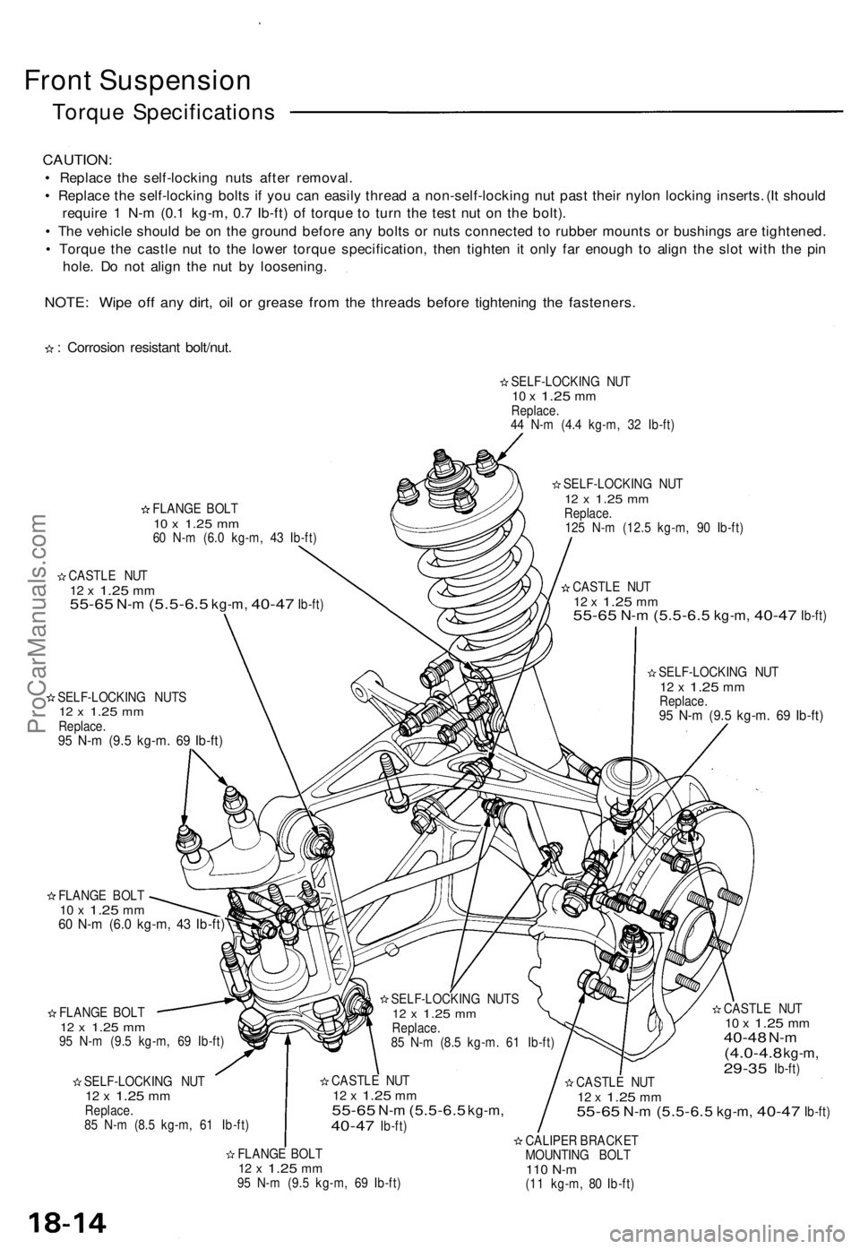
Torque Specifications
CAUTION:
• Replace the self-locking nuts after removal.
• Replace the self-locking bolts if you can easily thread a non-self-locking nut past their nylon locking inserts. (It should
require 1 N-m (0.1 kg-m, 0.7 Ib-ft) of torque to turn the test nut on the bolt).
• The vehicle should be on the ground before any bolts or nuts connected to rubber mounts or bushings are tightened.
• Torque the castle nut to the lower torque specification, then tighten it only far enough to align the slot with the pin
hole. Do not align the nut by loosening.
NOTE: Wipe off any dirt, oil or grease from the threads before tightening the fasteners.
: Corrosion resistant bolt/nut.
FLANGE BOLT
10 x
1.25
mm
60 N-m (6.0 kg-m, 43 Ib-ft)
CASTLE NUT
12 x
1.25
mm
55-65
N-m
(5.5-6.5
kg-m,
40-47
Ib-ft)
SELF-LOCKING NUTS
12 x
1.25
mm
Replace.
95 N-m (9.5 kg-m. 69 Ib-ft)
SELF-LOCKING NUT
10 x
1.25
mm
Replace.
44 N-m (4.4 kg-m, 32 Ib-ft)
SELF-LOCKING NUT
12 x
1.25
mm
Replace.
125 N-m (12.5 kg-m, 90 Ib-ft)
CASTLE NUT
12 x
1.25
mm
55-65
N-m
(5.5-6.5
kg-m,
40-47
Ib-ft)
SELF-LOCKING NUT
12 x
1.25
mm
Replace.
95 N-m (9.5 kg-m. 69 Ib-ft)
FLANGE BOLT
10 x
1.25
mm
60 N-m (6.0 kg-m, 43 Ib-ft)
FLANGE BOLT
12 x
1.25
mm
95 N-m (9.5 kg-m, 69 Ib-ft)
SELF-LOCKING NUT
12 x
1.25
mm
Replace.
85 N-m (8.5 kg-m, 61 Ib-ft)
CASTLE NUT
10 x
1.25
mm
40-48
N-m
(4.0-4.8
kg-m,
29-35
Ib-ft)
CASTLE NUT
12 x
1.25
mm
55-65
N-m
(5.5-6.5
kg-m,
40-47
Ib-ft)
FLANGE BOLT
12 x
1.25
mm
95 N-m (9.5 kg-m, 69 Ib-ft)
CALIPER BRACKET
MOUNTING BOLT
110 N-m
(11 kg-m, 80 Ib-ft)
CASTLE NUT
12 x
1.25
mm
55-65
N-m
(5.5-6.5
kg-m,
40-47
Ib-ft)
SELF-LOCKING NUTS
12 x
1.25
mm
Replace.
85 N-m (8.5 kg-m. 61 Ib-ft)ProCarManuals.com
Page 464 of 1640
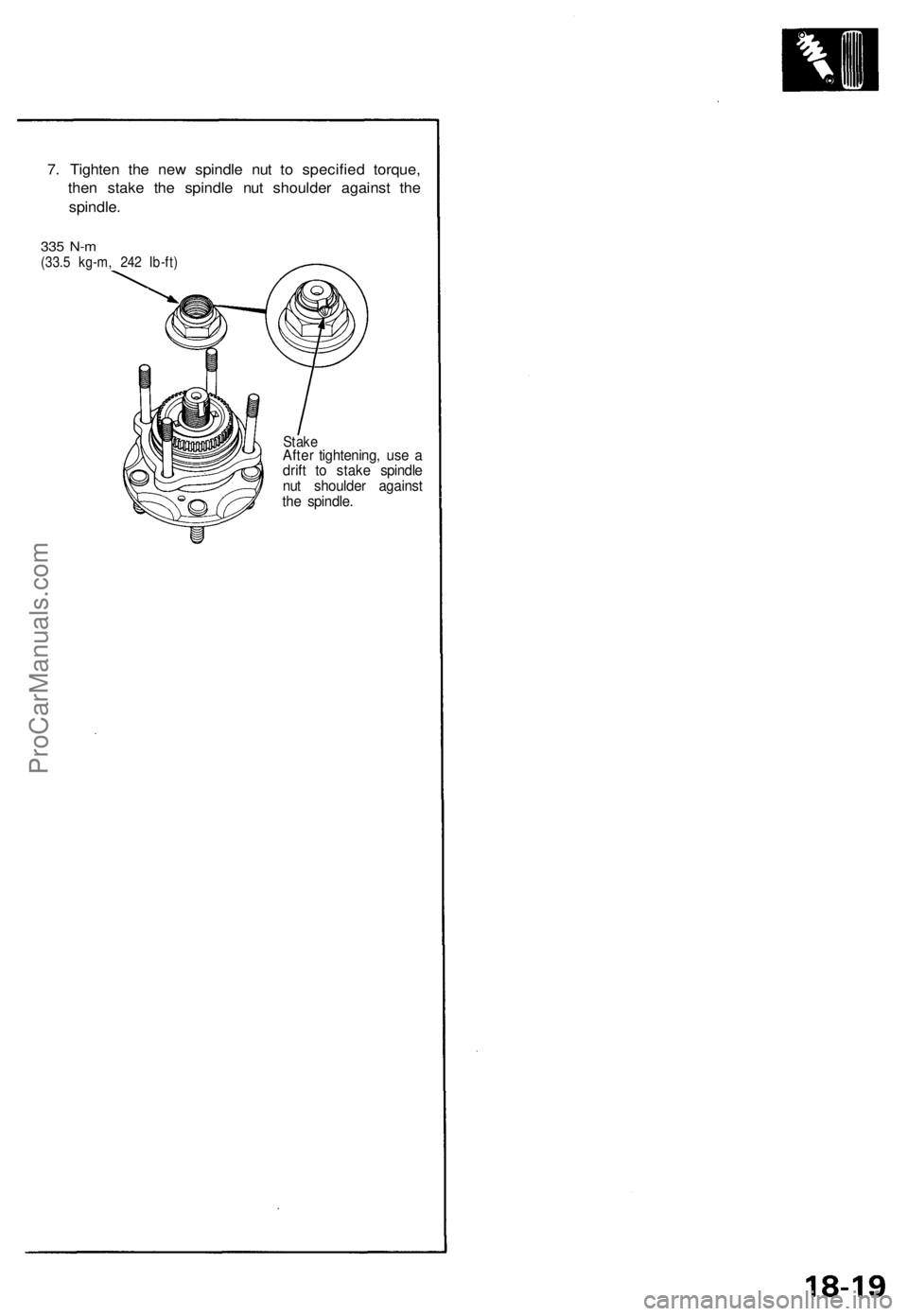
7. Tighten the new spindle nut to specified torque,
then stake the spindle nut shoulder against the
spindle.
335 N-m
(33.5 kg-m, 242 Ib-ft)
Stake
After tightening, use a
drift to stake spindle
nut shoulder against
the spindle.ProCarManuals.com
Page 470 of 1640
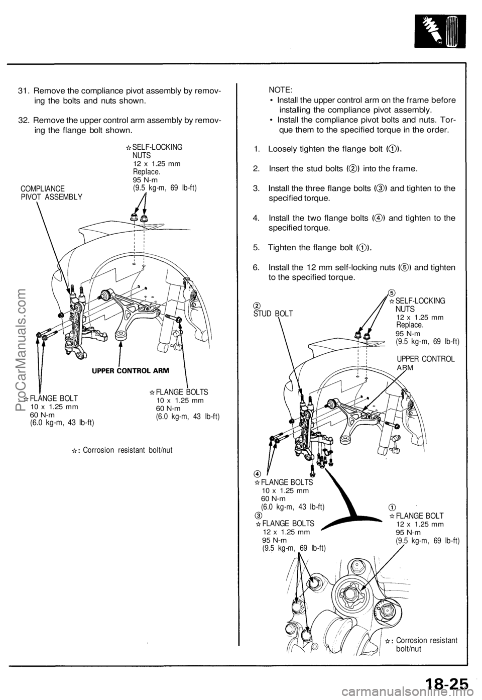
31. Remove the compliance pivot assembly by remov-
ing the bolts and nuts shown.
32. Remove the upper control arm assembly by remov-
ing the flange bolt shown.
SELF-LOCKING
NUTS
12 x
1.25
mm
Replace.
95 N-m
(9.5 kg-m, 69 Ib-ft)
FLANGE BOLT
10 x
1.25
mm
60 N-m
(6.0 kg-m, 43 Ib-ft)
FLANGE BOLTS
10 x
1.25
mm
60 N-m
(6.0 kg-m, 43 Ib-ft)
Corrosion resistant bolt/nut
NOTE:
• Install the upper control arm on the frame before
installing the compliance pivot assembly.
• Install the compliance pivot bolts and nuts. Tor-
que them to the specified torque in the order.
1. Loosely tighten the flange bolt
2. Insert the stud bolts into the frame.
3. Install the three flange bolts and tighten to the
specified torque.
4. Install the two flange bolts and tighten to the
specified torque.
5. Tighten the flange bolt
6. Install the 12 mm self-locking nuts and tighten
to the specified torque.
STUD BOLT
FLANGE BOLTS
10 x
1.25
mm
60 N-m
(6.0 kg-m, 43 Ib-ft)
FLANGE BOLTS
12 x
1.25
mm
95 N-m
(9.5 kg-m, 69 Ib-ft)
SELF-LOCKING
NUTS
12 x
1.25
mm
Replace.
95 N-m
(9.5 kg-m, 69 Ib-ft)
UPPER CONTROL
ARM
FLANGE BOLT
12 x
1.25
mm
95 N-m
(9.5 kg-m, 69 Ib-ft)
Corrosion resistant
bolt/nut
COMPLIANCE
PIVOT ASSEMBLYProCarManuals.com
Page 475 of 1640
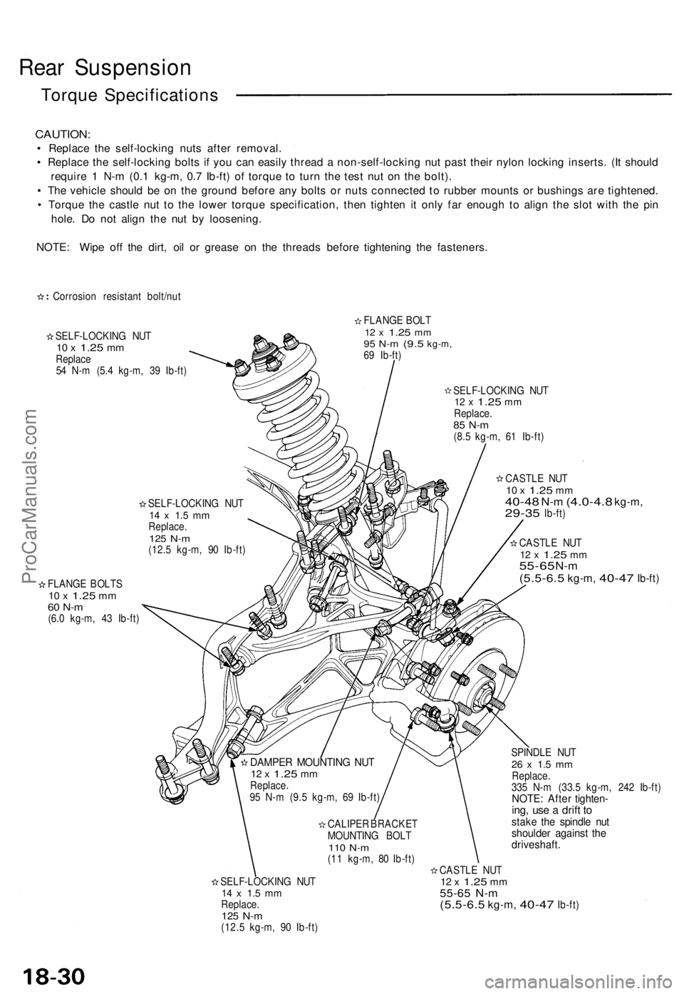
Rear Suspension
Torque Specifications
CAUTION:
• Replace the self-locking nuts after removal.
• Replace the self-locking bolts if you can easily thread a non-self-locking nut past their nylon locking inserts. (It should
require 1 N-m (0.1 kg-m, 0.7 Ib-ft) of torque to turn the test nut on the bolt).
• The vehicle should be on the ground before any bolts or nuts connected to rubber mounts or bushings are tightened.
• Torque the castle nut to the lower torque specification, then tighten it only far enough to align the slot with the pin
hole. Do not align the nut by loosening.
NOTE: Wipe off the dirt, oil or grease on the threads before tightening the fasteners.
Corrosion resistant bolt/nut
SELF-LOCKING NUT
10 x
1.25
mm
Replace
54 N-m (5.4 kg-m, 39 Ib-ft)
FLANGE BOLT
12 x
1.25
mm
95 N-m
(9.5
kg-m,
69 Ib-ft)
SELF-LOCKING NUT
12 x
1.25
mm
Replace.
85 N-m
(8.5 kg-m, 61 Ib-ft)
SELF-LOCKING NUT
14 x 1.5 mm
Replace.
125 N-m
(12.5 kg-m, 90 Ib-ft)
FLANGE BOLTS
10 x
1.25
mm
60 N-m
(6.0 kg-m, 43 Ib-ft)
CASTLE NUT
10 x
1.25
mm
40-48
N-m
(4.0-4.8
kg-m,
29-35
lb-ft)
CASTLE NUT
12 x
1.25
mm
55-65
N-m
(5.5-6.5
kg-m,
40-47
Ib-ft)
SPINDLE NUT
26 x 1.5 mm
Replace.
335 N-m (33.5 kg-m, 242 Ib-ft)
NOTE: After tighten-
ing, use a drift to
stake the spindle nut
shoulder against the
driveshaft.
SELF-LOCKING NUT
14 x 1.5 mm
Replace.
125 N-m
(12.5 kg-m, 90 Ib-ft)
CASTLE NUT
12 x
1.25
mm
55-65 N-m
(5.5-6.5
kg-m,
40-47
Ib-ft)
DAMPER MOUNTING NUT
12 x
1.25
mm
Replace.
95 N-m (9.5 kg-m, 69 Ib-ft)
CALIPER BRACKET
MOUNTING BOLT
110 N-m
(11 kg-m, 80 Ib-ft)ProCarManuals.com