Page 764 of 1640

Ignition System
Spark Plug Inspection
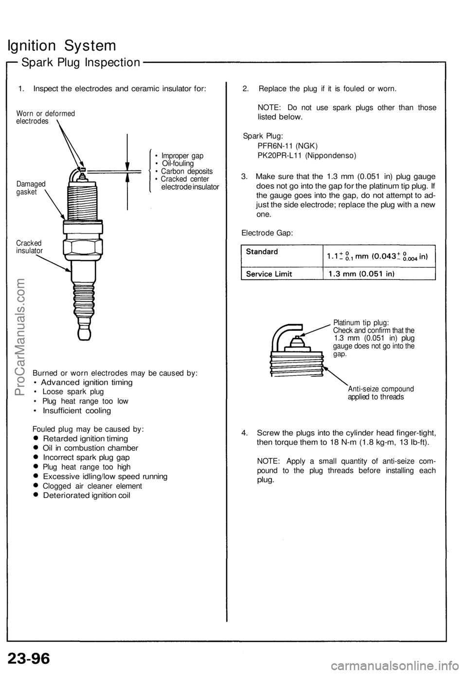
1. Inspect the electrodes and ceramic insulator for:
Worn or deformed
electrodes
Damaged
gasket
• Improper gap
• Oil-fouling
• Carbon deposits
• Cracked center
electrode insulator
Cracked
insulator
Burned or worn electrodes may be caused by:
• Advanced ignition timing
• Loose spark plug
• Plug heat range too low
• Insufficient cooling
Fouled plug may be caused by:
Retarded ignition timing
Oil in combustion chamber
Incorrect spark plug gap
Plug heat range too high
Excessive idling/low speed running
Clogged air cleaner element
Deteriorated ignition coil
2. Replace the plug if it is fouled or worn.
NOTE: Do not use spark plugs other than those
listed below.
Spark Plug:
PFR6N-11 (NGK)
PK20PR-L11 (Nippondenso)
3. Make sure that the 1.3 mm (0.051 in) plug gauge
does not go into the gap for the platinum tip plug. If
the gauge goes into the gap, do not attempt to ad-
just the side electrode; replace the plug with a new
one.
Electrode Gap:
Platinum tip plug:
Check and confirm that the
1.3 mm (0.051 in) plug
gauge does not go into the
gap.
Anti-seize compound
applied to threads
4. Screw the plugs into the cylinder head finger-tight,
then torque them to 18 N-m (1.8 kg-m, 13 Ib-ft).
NOTE: Apply a small quantity of anti-seize com-
pound to the plug threads before installing each
plug.ProCarManuals.com
Page 978 of 1640

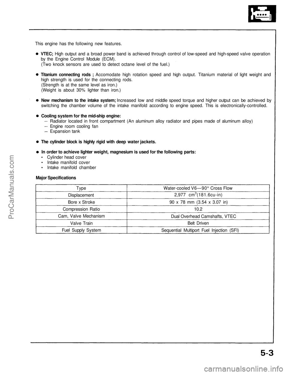
This engine has the following new features.
Type
Displacement
Bore x Stroke
Compression Ratio
Cam, Valve Mechanism
Valve Train
Fuel Supply System Water-cooled V6—90° Cross Flow
2,977 cm3(181.6cu-in)
90 x 78 mm
(3.54
x
3.07
in)
10.2
Dual Overhead Camshafts, VTEC Belt Driven
Sequential Multiport Fuel Injection (SFI)VTEC; High output and a broad power band is achieved through control of low-speed and high-speed valve operation
by the Engine Control Module (ECM).
(Two knock sensors are used to detect octane level of the fuel.)
Titanium connecting rods ; Accomodate high rotation speed and high output. Titanium material of light weight and
high strength is used for the connecting rods.
(Strength is at the same level as iron.)
(Weight is about 30% lighter than iron.)
New mechanism to the intake system; Increased low and middle speed torque and higher output can be achieved by
switching the chamber volume of the intake manifold according to engine speed. This is electronically-controlled.
Cooling system for the mid-ship engine:
Radiator located in front compartment (An aluminum alloy radiator and pipes made of aluminum alloy)
Engine room cooling fan
Expansion tank
The cylinder block is highly rigid with deep water jackets. In order to achieve lighter weight, magnesium is used for the following parts: Cylinder head coverIntake manifold cover
Intake manifold chamber
Major SpecificationsProCarManuals.com
Page 980 of 1640

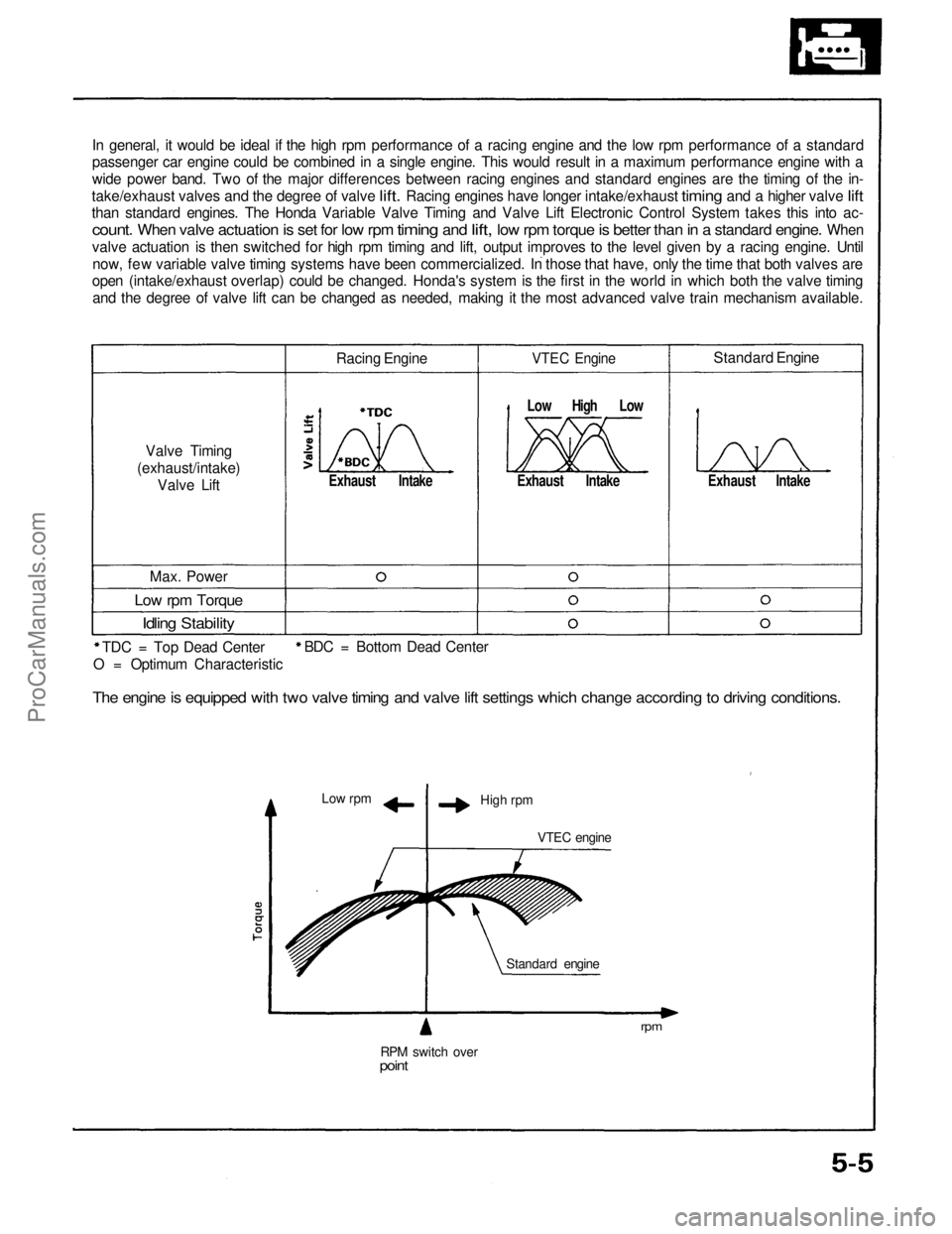
In general, it would be ideal if the high rpm performance of a racing engine and the low rpm performance of a standard
passenger car engine could be combined in a single engine. This would result in a maximum performance engine with a
wide power band. Two of the major differences between racing engines and standard engines are the timing of the in-
take/exhaust valves
and the
degree
of
valve
lift.
Racing engines have longer intake/exhaust
timing
and a
higher valve
lift
than standard engines. The Honda Variable Valve Timing and Valve Lift Electronic Control System takes this into ac-
count.
When
valve
actuation
is set for low rpm
timing
and
lift,
low rpm
torque
is
better
than
in a
standard
engine.
When
valve actuation is then switched for high rpm timing and lift, output improves to the level given by a racing engine. Untilnow, few variable valve timing systems have been commercialized. In those that have, only the time that both valves are
open (intake/exhaust overlap) could be changed. Honda's system is the first in the world in which both the valve timing
and the degree of valve lift can be changed as needed, making it the most advanced valve train mechanism available.
Valve Timing
(exhaust/intake) Valve Lift Racing Engine
Exhaust Intake
VTEC Engine
Low High Low
Exhaust Intake
Standard Engine
Exhaust Intake
Max. Power
Low rpm Torque
Idling Stability
TDC = Top Dead Center
Low rpm
High rpm
VTEC engine
RPM switch over
point
Standard engine
rpm
BDC = Bottom Dead Center
O = Optimum Characteristic
The engine is equipped with two valve timing and valve lift settings which change according to driving conditions.ProCarManuals.com
Page 991 of 1640
Engine Removal/Installation
(cont'd )
32. Remove the rear beam rod assembly.
33. Remove the front beam. Lower and suspend the air conditioning (A/C) compressor. Reinstall the frontbeam.
NOTE:
PARKING BRAKE CABLE
Hang with
wire or rope.
FRONT BEAM
REAR BEAM
ROD ASSEMBLY
Remove.
A/C COMPRESSOR
Do not remove the compressor hoses.
Hang the A/C compressor with wire
or rope as shown.
Do not let it hang from hoses.
Retorque the two nuts
NOTE:
Do not remove the compressor hoses.
Do not let the compressor hang from hoses.
34. Remove the left and right parking brake cables.
35. Disconnect the stabilizer bar end links from the knuckles, remove the bar. Separate the dampers
from the knuckles.ProCarManuals.com
Page 994 of 1640
45. Install the front engine mounting bolt, torque the
nut temporarily.
46. Position the Engine Removal/Installation Fixture (07MAK –PR7020A) under the car. Lower the car
just above the fixture. With the help of an assis-
tant, attach the fixture to the subframe with two 12 mm nuts and two 10 mm bolts. 47. Adjust the pads on the fixture to support the oil
pan and transmission housing.
48. Lower the car so the fixture is resting on its casters (or appropriate platform).
BODY SUPPORT
BRACKET
SIDE ENGINE
MOUNT
TRANSMISSION MOUNTING
BOLT
LOOSELY INSTALL
TWO 12 mm NUTS
ON STUDS HERE
LOOSELY
INSTALL
ONE 10 mm
BOLT HERE
ENGINE REMOVAL/INSTALLATION
FIXTURE
07MAK–PR7020A
(cont'd)ProCarManuals.com
Page 996 of 1640
55. Attach a chain hoist to the engine. Remove the
front and rear mounting bolts, then separate the
engine from the suspension and the beam
assembly.
CAUTION: Do not hit the engine oil cooler on the
rear right beam bracket.
FRONT ENGINE
MOUNT
REAR ENGINE
MOUNT
56. Install the engine in the reverse order of removal:
NOTE:
Combine the front beam and the rear beam rod
assembly, then torque the four mounting bolts.
Check that the set ring on the end of each
driveshaft clicks into place.
CAUTION: Use new set rings.
(cont'd)
Align the bolt holes of the beam brackets and
body with a tapered punch (page 5-28).
Temporarily torque the two front beam nuts and
front engine mounting bolt when installing the
A/C compressor.ProCarManuals.com
Page 997 of 1640
55. Attach a chain hoist to the engine. Remove the
front and rear mounting bolts, then separate the
engine from the suspension and the beam
assembly.
CAUTION: Do not hit the engine oil cooler on the
rear right beam bracket.
FRONT ENGINE
MOUNT
REAR ENGINE
MOUNT
56. Install the engine in the reverse order of removal:
NOTE:
Combine the front beam and the rear beam rod
assembly, then torque the four mounting bolts.
Check that the set ring on the end of each
driveshaft clicks into place.
CAUTION: Use new set rings.
(cont'd)
Align the bolt holes of the beam brackets and
body with a tapered punch (page 5-28).
Temporarily torque the two front beam nuts and
front engine mounting bolt when installing the
A/C compressor.ProCarManuals.com
Page 998 of 1640

Engine Removal/Installation
(cont'd)
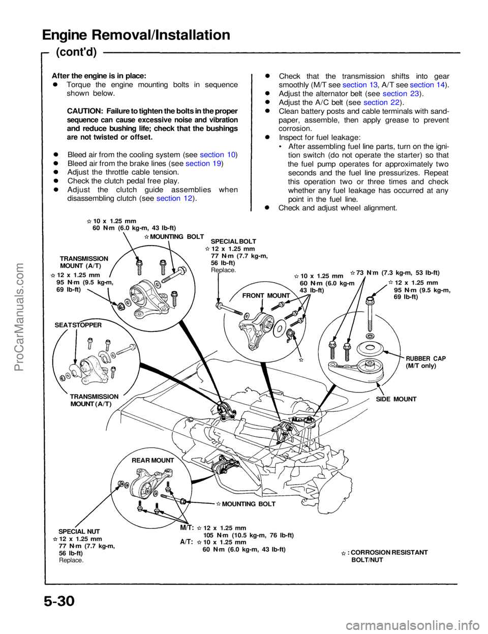
Torque the engine mounting bolts in sequenceshown below.
CAUTION: Failure to tighten the bolts in the proper
sequence can cause excessive noise and vibration
and reduce bushing life; check that the bushings
are not twisted or offset.
Bleed air from the cooling system (see section 10)
Bleed air from the brake lines (see section 19)
Adjust the throttle cable tension.
Check the clutch pedal free play.
Adjust the clutch guide assemblies when
disassembling clutch (see section 12). Check that the transmission shifts into gear
smoothly (M/T see section 13, A/T see section 14).
Adjust the alternator belt (see section 23).
Adjust the A/C belt (see section 22).
Clean battery posts and cable terminals with sand-
paper, assemble, then apply grease to prevent
corrosion.
Inspect for fuel leakage:
• After assembling fuel line parts, turn on the igni- tion switch (do not operate the starter) so that
the fuel pump operates for approximately two seconds and the fuel line pressurizes. Repeat
this operation two or three times and check whether any fuel leakage has occurred at any
point in the fuel line.
Check and adjust wheel alignment.
10 x
1.25
mm
60 N .
m (6.0 kg-m, 43 Ib-ft)
MOUNTING BOLT SPECIAL BOLT
12 x
1.25
mm
77 N .
m
(7.7 kg-m,
56 Ib-ft)
Replace.
10 x
1.25
mm
60 N .
m
(6.0 kg-m
43 Ib-ft) 73 N.m (7.3 kg-m, 53 Ib-ft)
12 x
1.25
mm
95 N .
m
(9.5 kg-m,
69 Ib-ft)
RUBBER CAP
(M/T only)
SIDE MOUNT
: CORROSION RESISTANT
BOLT/NUT
12 x
1.25
mm
105 N .
m (10.5 kg-m, 76 Ib-ft)
10 x
1.25
mm
60 N .
m (6.0 kg-m, 43 Ib-ft) MOUNTING BOLT FRONT MOUNT
TRANSMISSION
MOUNT (A/T)
12 x
1.25
mm
95 N .
m
(9.5 kg-m,
69 Ib-ft)
SEAT STOPPER
TRANSMISSION
MOUNT (A/T)
REAR MOUNT
SPECIAL NUT
12 x
1.25
mm
77 N .
m
(7.7 kg-m,
56 Ib-ft)
Replace.
M/T:
A/T:
After the engine is in place:ProCarManuals.com