1991 ACURA NSX torque
[x] Cancel search: torquePage 1039 of 1640
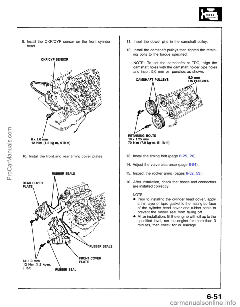
9. Install the CKP/CYP sensor on the front cylinder
head.
CKP/CYP SENSOR
6 x 1.0 mm
12 N.m (1.2 kg-m, 9 Ib-ft)
10. Install the front and rear timing cover plates.
RUBBER SEALS
REAR COVER
PLATE
6x 1.0 mm
12 N.m
(1.2 kg-m.
9 Ib-ft)
RUBBER SEAL
FRONT COVER
PLATE
RUBBER SEALS
11. Insert the dowel pins in the camshaft pulley.
12. Install the camshaft pulleys then tighten the retain-
ing bolts to the torque specified.
NOTE: To set the camshafts at TDC, align the
camshaft holes with the camshaft holder pipe holes
and insert 5.0 mm pin punches as shown.
CAMSHAFT PULLEYS
5.0 mm
PIN PUNCHES
RETAINING BOLTS
10 x
1.25
mm
70 N.m (7.0 kg-m, 51 Ib-ft)
13. Install the timing belt (page 6-25, 26).
14. Adjust the valve clearance (page 6-54).
15. Inspect the rocker arms (pages 6-52, 53).
16. After installation, check that hoses and connectors
are installed correctly.
Prior to installing the cylinder head cover, apply
a thin layer of liquid gasket to the mating surface of the cylinder head cover and rubber seals to
prevent the rubber seal from falling off.
After installation, fill the engine with oil up to the
specified level, run the engine for more than 3
minutes, then check for oil leakage.
NOTE:ProCarManuals.com
Page 1085 of 1640
3. Fuel Cut-off Control
During deceleration with the throttle valve closed, current to the fuel injectors is cut off to improve fuel economy
at speeds over 1,500 rpm.
Fuel cut-off action also takes place when engine speed exceeds, 8,300 rpm, regardless of the position of the
throttle valve, to protect the engine from over-revving.
4. A/C Compressor Clutch Relay
When the ECM receives a demand for cooling from the air conditioning system, it delays the compressor from being
energized, and enriches the mixture to assure smooth translation to the A/C mode.
5. Evaporative Emission (EVAP) Purge Control Solenoid Valve
When the engine coolant temperature is below 1 58 °F (70°C) the ECM supplies a ground to the EVAP purge control
solenoid valve which cuts vacuum to the EVAP purge control diaphragm valve.
6. Intake Air Bypass (IAB) Control Solenoid Valve
When the engine speed is below 4,800 rpm, the IAB control solenoid valve is activated by a signal from the ECM.
Intake air then flows through the smaller chamber, and hight torque is delivered. To increase air flow at engine speeds
higher than 4,800 rpm, the solenoid valve is deactivated by the ECM, and the intake air flows through the larger
chamber.
7. Exhaust Gas Recirculation (EGR) Control Solenoid Valve
When the EGR is required for control of oxides of nitrogen (NOx) emissions, the ECM supplies ground to the EGR
control solenoid valve which supplies regulated vacuum to the EGR valve.
ECM fail-safe/back-up Functions
1. Fail-Safe Function
When an abnormality occurs in a signal from a sensor, the ECM ignores that signal and assumes a pre-programmed
valve for that sensor that allows the engine to continue to run.
2. Back-up Function
When an abnormality occurs in the ECM itself, the fuel injectors are controlled by a back-up circuit independent of
the system in order to permit minimal driving.
3. Self-diagnosis Function [Malfunction Indicator Lamp (MIL)]
When an abnormality occurs in a signal from a sensor, the ECM lights the MIL and stores the diagnostic trouble code
in erasable memory. When the ignition is initially turned in, the ECM supplies ground for the MIL for two seconds
to check the MIL bulb condition.ProCarManuals.com
Page 1159 of 1640
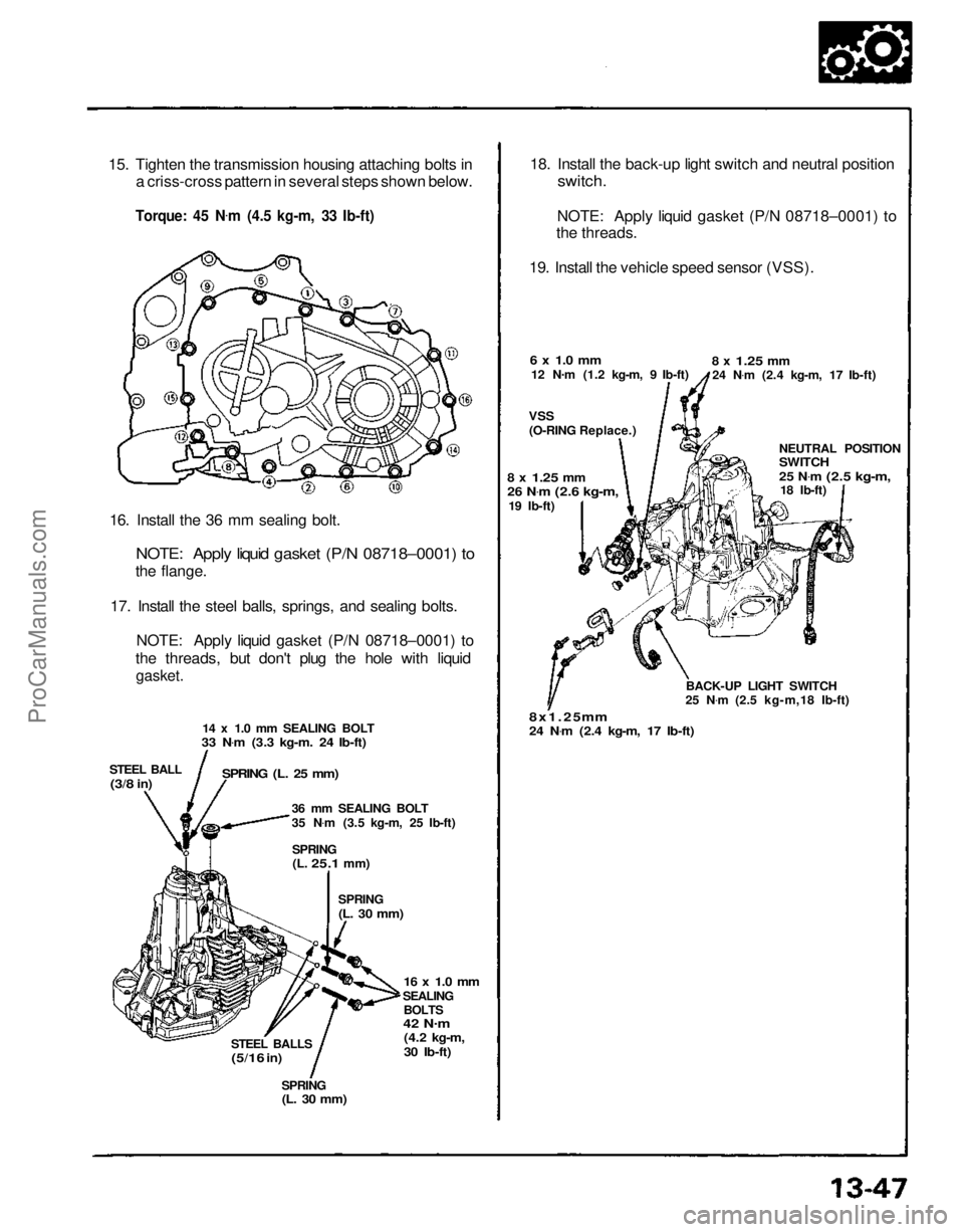
15. Tighten the transmission housing attaching bolts in
a criss-cross pattern in several steps shown below.
Torque: 45 N .
m (4.5 kg-m, 33 Ib-ft)
16. Install the 36 mm sealing bolt.
NOTE: Apply liquid gasket (P/N 08718–0001) to
the flange.
17. Install the steel balls, springs, and sealing bolts. NOTE: Apply liquid gasket (P/N 08718–0001) to
the threads, but don't plug the hole with liquid
gasket.
14 x 1.0 mm SEALING BOLT
33 N .
m (3.3 kg-m. 24 Ib-ft)
STEEL BALL
(3/8
in)
SPRING (L. 25 mm)
36 mm SEALING BOLT
35 N.
m (3.5 kg-m, 25 Ib-ft)
SPRING
(L.
25.1
mm)
SPRING
(L. 30 mm)
16 x 1.0 mm
SEALING BOLTS
42 N .
m
(4.2 kg-m,
30 Ib-ft)
STEEL BALLS
(5/16
in)
SPRING
(L. 30 mm)
18. Install the back-up light switch and neutral position
switch.
NOTE: Apply liquid gasket (P/N 08718–0001) to
the threads.
19. Install the vehicle speed sensor (VSS).
6 x 1.0 mm
12 N .
m (1.2 kg-m, 9 Ib-ft)
VSS
(O-RING Replace.)
8 x
1.25
mm
24 N .
m (2.4 kg-m, 17 Ib-ft)
NEUTRAL POSITION
SWITCH
25 N.
m
(2.5 kg-m,
18 Ib-ft)
BACK-UP LIGHT SWITCH
25 N .
m (2.5 kg-m,18 Ib-ft)
8x1.25 mm
24 N .
m (2.4 kg-m, 17 Ib-ft)
8 x
1.25
mm
26 N
.
m
(2.6 kg-m,
19 Ib-ft)ProCarManuals.com
Page 1165 of 1640
Description
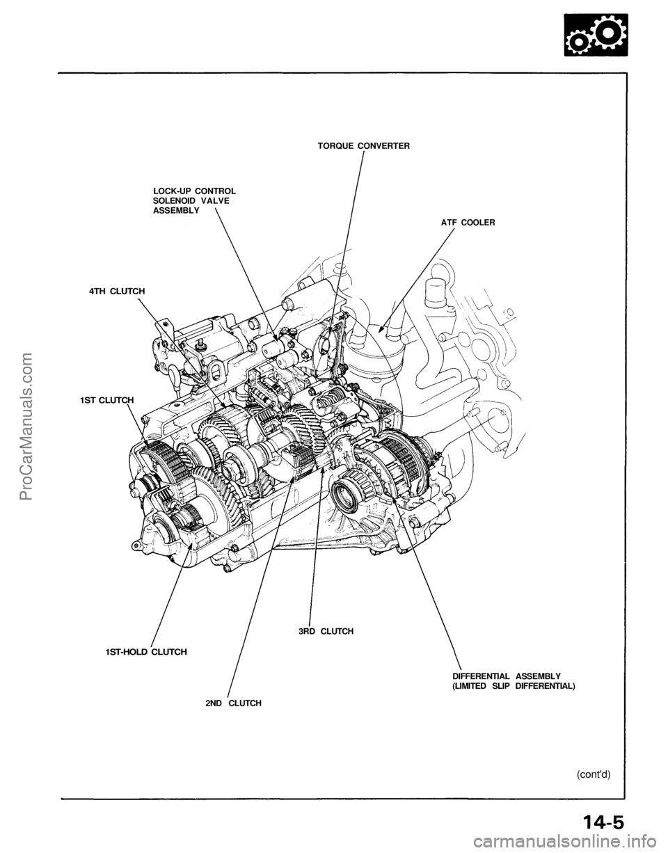
The automatic transmission is a combination of a 3-element torque converter and a triple-shaft electronically controlled
automatic transmission which provides 4 speeds forward and 1 in reverse. The entire unit is positioned in line with the
engine.
TORQUE CONVERTER, GEARS AND CLUTCHES
The torque converter consists of a pump, turbine and stator, assembled in a single unit.
They are connected to the engine crankshaft so they turn together as a unit as the engine turns.
Around the outside of the torque converter is a ring gear which meshes with the starter pinion when the engine is being
started. The entire torque converter assembly serves as a flywheel while transmitting power to the transmission mainshaft.
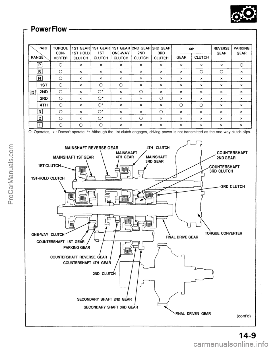
The transmission has three parallel shafts, the mainshaft, the countershaft, and the secondary shaft. The mainshaft is
in line with the engine crankshaft.
The mainshaft includes the clutches for 1st, and 4th, and gears for 3rd, 4th, Reverse and 1st (3rd gear is integral with
the mainshaft, while reverse gear is integral with 4th gear).
The countershaft includes the clutches for 1st-Hold and 3rd, and gears for 2nd, 3rd, 4th, Reverse and 1st.
The secondary shaft includes the 2nd clutch and gears for 2nd and 3rd.
The 4th and reverse gears can be locked to the countershaft at its center, providing 4th gear or Reverse, depending on
which way the selector is moved.
The gears on the mainshaft and secondary shaft are in constant mesh with those on the countershaft.
When certain combinations of gears in the transmission are engaged by clutches, power is transmitted from the main-
shaft to the countershaft to provide , , , and
ELECTRONIC CONTROL
The electronic control system consists of the Transmission Control Module (TCM), sensors, a linear solenoid and 4
solenoid valves. Shifting and lock-up are electronically controlled for comfortable driving under all conditions.
The TCM is located on the insulator center bulkhead, behind the driver's seat.
HYDRAULIC CONTROL
The valve bodies include the main valve body, secondary valve body, servo body, regulator valve body, throttle valve
body, lock-up valve body and the 2nd accumulator body.
They are bolted to the torque converter housing as an assembly.
The main valve body contains the manual valve, 1-2 shift valve, 2-3 shift valve, 3-4 shift valve, relief valve, one-way
relief valve and oil pump gears.
The secondary valve body contains the 3-2 kick-down valve, CPC (clutch pressure control) valve, 2nd orifice control
valve, 3rd orifice control valve, modulator valve, 4th exhaust valve, servo control valve, 2nd exhaust valve and 4-3 kick-
down valve.
The servo body contains the accumulator pistons and servo valve. The throttle valve body includes the throttle valve B
which is bolted onto the servo body.
The regulator valve body contains the pressure regulator valve, lock-up control valve and cooler relief valve. Fluid from
the regulator passes through the manual valve to the various control valves.
The lock-up valve body contains the lock-up timing B valve and lock-up shift valve. The 2nd accumulator body contains
the accumulator pistons and limited slip differential (LSD) relief valve.
The torque converter check valve is located in the torque converter housing, under the main valve body.
The 1st, 1st-hold, 3rd and 4th clutches receive oil from their respective feed pipes.
SHIFT CONTROL MECHANISM
Input from various sensors located throughout the car determines which shift control solenoid valve the TCM will ac-
tivate. Activating a shift control solenoid valve changes modulator pressure, causing a shift valve to move. This
pressurizes a line to one of the clutches, engaging that clutch and its corresponding gear.
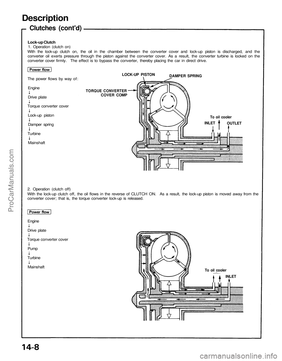
LOCK-UP MECHANISM
In position and position in 2nd, 3rd and 4th, pressurized fluid is drained from the back of the torque converter
through an oil passage, causing the lock-up piston to be held, against the torque converter cover. As this takes place, the
mainshaft rotates at the same speed as the engine crankshaft. Together with hydraulic control, the TCM optimizes the
timing of the lock-up mechaism.
The lock-up valves control the range of lock-up according to lock-up control solenoid valves A and B, and throttle valve B.
When lock-up control solenoid valves A and B activate, modulator pressure changes. The lock-up control solenoid valves
A and B are mounted on the torque converter housing, and are controlled by the TCM.
(cont'd)ProCarManuals.com
Page 1167 of 1640
LOCK-UP CONTROL
SOLENOID VALVE
ASSEMBLY
TORQUE CONVERTER
ATF COOLER
4TH CLUTCH
1ST CLUTCH
1ST-HOLD CLUTCH
2ND CLUTCH
3RD CLUTCH
DIFFERENTIAL ASSEMBLY
(LIMITED SLIP DIFFERENTIAL)
(cont'd)ProCarManuals.com
Page 1170 of 1640
Description
Clutches (cont'd)
Lock-up Clutch
1. Operation (clutch on)
With the lock-up clutch on, the oil in the chamber between the converter cover and lock-up piston is discharged, and the
converter oil exerts pressure through the piston against the converter cover. As a result, the converter turbine is locked on the
converter cover firmly. The effect is to bypass the converter, thereby placing the car in direct drive.
The power flows by way of:
2. Operation (clutch off)
With the lock-up clutch off, the oil flows in the reverse of CLUTCH ON. As a result, the lock-up piston is moved away from the
converter cover; that is, the torque converter lock-up is released.
Engine
To oil cooler
INLET
To oil cooler
INLET
OUTLET
TORQUE CONVERTER
COVER COMP
LOCK-UP PISTON
DAMPER SPRING
Engine
Drive plate
Torque converter cover
Lock-up piston
Damper spring
Turbine
Mainshaft
Drive plate
Torque converter cover
Pump
Turbine
MainshaftProCarManuals.com
Page 1171 of 1640
Power Flow
MAINSHAFT REVERSE GEAR
MAINSHAFT 1ST GEAR
1ST CLUTCH
1ST-HOLD CLUTCH
ONE-WAY CLUTCH COUNTERSHAFT 1ST GEAR PARKING GEAR
COUNTERSHAFT REVERSE GEAR COUNTERSHAFT 4TH GEAR
2ND CLUTCH
SECONDARY SHAFT 2ND GEAR SECONDARY SHAFT 3RD GEAR FINAL DRIVEN GEAR
(cont'd)
FINAL DRIVE GEAR
TORQUE CONVERTER
3RD CLUTCH
COUNTERSHAFT
3RD CLUTCH COUNTERSHAFT
2ND GEAR
4TH CLUTCH
MAINSHAFT
3RD GEAR
MAINSHAFT
4TH GEAR
O: Operates, x : Doesn't operate.
Although the 1st clutch engages, driving power is not transmitted as the one-way clutch slips.ProCarManuals.com
Page 1172 of 1640
Description
Power Flow (cont'd)
Position
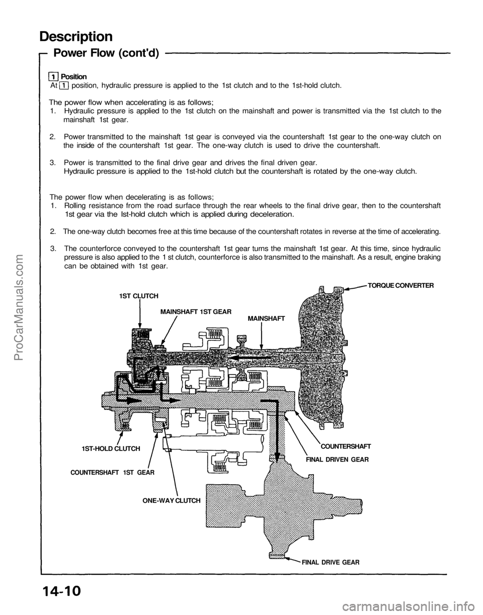
At position, hydraulic pressure is applied to the 1st clutch and to the 1st-hold clutch.
The power flow when accelerating is as follows;
1. Hydraulic pressure is applied to the 1st clutch on the mainshaft and power is transmitted via the 1st clutch to the
mainshaft 1st gear.
2. Power transmitted to the mainshaft 1st gear is conveyed via the countershaft 1st gear to the one-way clutch on
the inside of the countershaft 1st gear. The one-way clutch is used to drive the countershaft.
3. Power is transmitted to the final drive gear and drives the final driven gear.
Hydraulic pressure is applied to the 1st-hold clutch but the countershaft is rotated by the one-way clutch.
The power flow when decelerating is as follows;
1. Rolling resistance from the road surface through the rear wheels to the final drive gear, then to the countershaft
1st gear via the Ist-hold clutch which is applied during deceleration.
2. The one-way clutch becomes free at this time because of the countershaft rotates in reverse at the time of accelerating.
3. The counterforce conveyed to the countershaft 1st gear turns the mainshaft 1st gear. At this time, since hydraulic
pressure is also applied to the 1 st clutch, counterforce is also transmitted to the mainshaft. As a result, engine braking
can be obtained with 1st gear.
1ST CLUTCH
MAINSHAFT 1ST GEAR
MAINSHAFT
TORQUE CONVERTER
COUNTERSHAFT
FINAL DRIVEN GEAR
1ST-HOLD CLUTCH
COUNTERSHAFT 1ST GEAR
ONE-WAY CLUTCH
FINAL DRIVE GEARProCarManuals.com