Page 1237 of 1640
Illustrated Index
Torque Converter Housing/Valve BodyProCarManuals.com
Page 1238 of 1640

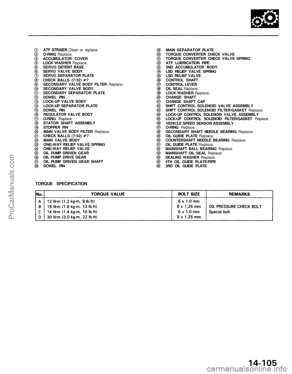
ATF STRAIER Clean or replace.
O-RING
Replace.
ACCUMULATOR COVER
LOCK WASHER
Replace.
SERVO DETENT BASE
SERVO VALVE BODY
SERVO SEPARATOR PLATE CHECK BALLS (7/32) 7
SECONDARY VALVE BODY FILTER
Replace.
SECONDARY VALVE BODY
SECONDARY SEPARATOR PLATE
DOWEL PIN
LOCK-UP VALVE BODY
LOCK-UP SEPARATOR PLATE
DOWEL PIN REGULATOR VALVE BODY
O-RING
Replace.
STATOR SHAFT ASSEMBLY
STOPPER PIN
MAIN VALVE BODY FILTER
Replace. CHECK BALLS (7/32) 7
MAIN VALVE BODY
ONE-WAY RELIEF VALVE SPRING
ONE-WAY RELIEF VALVE
OIL PUMP DRIVEN GEAR
OIL PUMP DRIVE GEAR
OIL PUMP DRIVEN GEAR SHAFT
DOWEL PIN MAIN SEPARATOR PLATE
TORQUE CONVERTER CHECK VALVE
TORQUE CONVERTER CHECK VALVE SPRING ATF LUBRICATION PIPE
2ND ACCUMULATOR BODY
LSD RELIEF VALVE SPRINGLSD RELIEF VALVE
CONTROL SHAFT
CONTROL LEVER
OIL SEAL
Replace.
LOCK WASHER
Replace.
CHANGE SHAFT
CHANGE SHAFT CAP
SHIFT CONTROL SOLENOID VALVE ASSEMBLY
SHIFT CONTROL SOLENOID FILTER/GASKET
Replace.
LOCK-UP CONTROL SOLENOID VALVE ASSEMBLY
LOCK-UP CONTROL SOLENOID FILTER/GASKET
Replace.
VEHICLE SPEED SENSOR ASSEMBLY
O-RING Replace.
SECONDARY SHAFT NEEDLE BEARING
Replace.
OIL GUIDE PLATE
Replace.
COUNTERSHAFT NEEDLE BEARING
Replace.
OIL GUIDE PLATE
Replace.
MAINSHAFT BALL BEARING
Replace.
MAINSHAFT OIL SEAL
Replace.
SEALING WASHER
Replace.
4TH OIL GUIDE PLATE/PIPE
3RD OIL GUIDE PLATE
TORQUE SPECIFICATIONProCarManuals.com
Page 1241 of 1640
Replace.
7 Bolts
5 Bolts
2 Bolts
2 Bolts
Replace.
2 Bolts
5 Bolts
4 Bolts
7 Bolts
Valve Body
Removal
NOTE:
1. Remove the valve body in the following numbered sequence.
CAUTION: Do not use a magnet to remove the check balls; it may magnetize the balls.
Clean all parts thoroughly in solvent or carburetor cleaner and dry with compressed air. Blow out all passages.
Accumulator covers are spring loaded; to prevent stripping the threads in the torque converter housing, press down
on the accumulator covers while unscrewing the bolts in a crisscross pattern.ProCarManuals.com
Page 1248 of 1640
NOTE: All check balls are the same size (7/32)#7.
TORQUE CONVERTER
CHECK VALVE
TORQUE CONVERTER
CHECK VALVE SPRING TORQUE CONVERTER
HOUSING
CHECK BALL
MAIN VALVE
BODY
CHECK BALL
CHECK BALL
1ST CHECK
BALL
4TH CHECK
BALL
Unit of length: mm (in)
SPRING SPECIFICATIONS
Spring
No.
1-2 shift spring
3-4 shift spring
Relief valve spring
One-way relief valve spring
2-3 shift spring
Torque converter check valve spring
Wire Dia.
O.D.Standard (New)
Free Length
0.9 (0.035)
0.8 (0.031)
1.1 (0.043)
0.9 (0.035)
0.8 (0.031)
1.1 (0.043)
8.6 (0.339)
7.0 (0.276)
8.4 (0.331)
6.4 (0.252)
7.0 (0.276)
8.4 (0.331)
40.4 (1.591)
43.7 (1.720)
44.4 (1.748)
25.1 (0.988)
43.7 (1.720)
41.8 (1.646)
No. of Coils
14.5
21.2
19.5
11.9
21.2 15.7
MAIN VALVE
BODY
Sectional view.
ProCarManuals.com
Page 1260 of 1640
9. Torque the countershaft locknut to 30 N
.
m (3.0 kg-m,
22 Ib-ft).
COUNTERSHAFT BEARING 11. If the clearance is out of tolerance, select and install a
new cotter retainer.
THICKNESS
COTTER RETAINER
COTTER RETAINER
12. After replacing the cotter retainer, make sure that
the clearance is within tolerance.
LOCK NUT
30 N
.
m
(3.0 kg-m, 22 Ib-ft)
10. Measure the clearance between 4th gear and reverse selector hub with a feeler gauge.
NOTE: Take measurements in at least three places,
and take the average as the actual clearance.
FEELER GAUGE
COTTER RETAINER 4TH GEAR REVERSE SELECTOR HUBProCarManuals.com
Page 1275 of 1640
Torque Converter Housing Bearings
Mainshaft Bearing Replacement
1. Drive out the mainshaft bearing and oil seal using the special tools as shown. 3. Install the new oil seal flush with the housing using
the special tools as shown.
DRIVER
07749–0010000
ATTACHMENT,
72 x 75 mm
07746–0010600
ATTACHMENT,
07947–6340500
TORQUE CONVERTER HOUSING
2. Drive in the new mainshaft bearing until it bottoms in the housing, using the special tools as shown.
DRIVER
07749–0010000
ATTACHMENT,
62 x 68 mm
07746–0010500
DRIVER
07749–0010000ProCarManuals.com
Page 1279 of 1640

Manual Valve Detent Spring
Parking Brake Stopper
Replacement/Adjustment
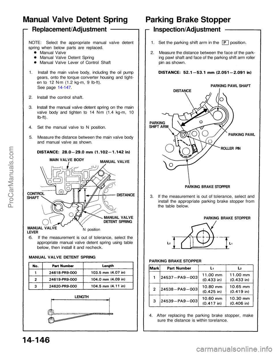
NOTE: Select the appropriate manual valve detent
spring when below parts are replaced. Manual Valve
Manual Valve Detent Spring
Manual Valve Lever of Control Shaft
1. Install the main valve body, including the oil pump gears, onto the torque converter housing and tight-
en to 12 N .
m (1.2 kg-m, 9 Ib-ft).
See page 14-147.
2. Install the control shaft.
3. Install the manual valve detent spring on the main
valve body and tighten to 14 N .
m (1.4 kg-m, 10
Ib-ft).
4. Set the manual valve to N position. 5. Measure the distance between the main valve body and manual valve as shown.
Inspection/Adjustment
1. Set the parking shift arm in the position.
2. Measure the distance between the face of the park- ing pawl shaft and face of the parking shift arm roller
pin as shown.
PARKING PAWL SHAFT
DISTANCE
PARKING PAWL
ROLLER PIN
PARKING
SHIFT ARM
PARKING BRAKE STOPPER
MANUAL VALVE
MAIN VALVE BODY
DISTANCE
3. If the measurement is out of tolerance, select and
install the appropriate parking brake stopper from
the table below.
PARKING BRAKE STOPPER
MANUAL VALVE
DETENT SPRING
CONTROL
N position
MANUAL VALVE
LEVER
5. If the measurement is out of tolerance, select the appropriate manual valve detent spring using table
below, then install it and recheck.
PARKING BRAKE STOPPER
MANUAL VALVE DETENT SPRING
4. After replacing the parking brake stopper, makesure the distance is within torelance.
LENGTH
SHAFTProCarManuals.com
Page 1280 of 1640

Transmission
Reassembly
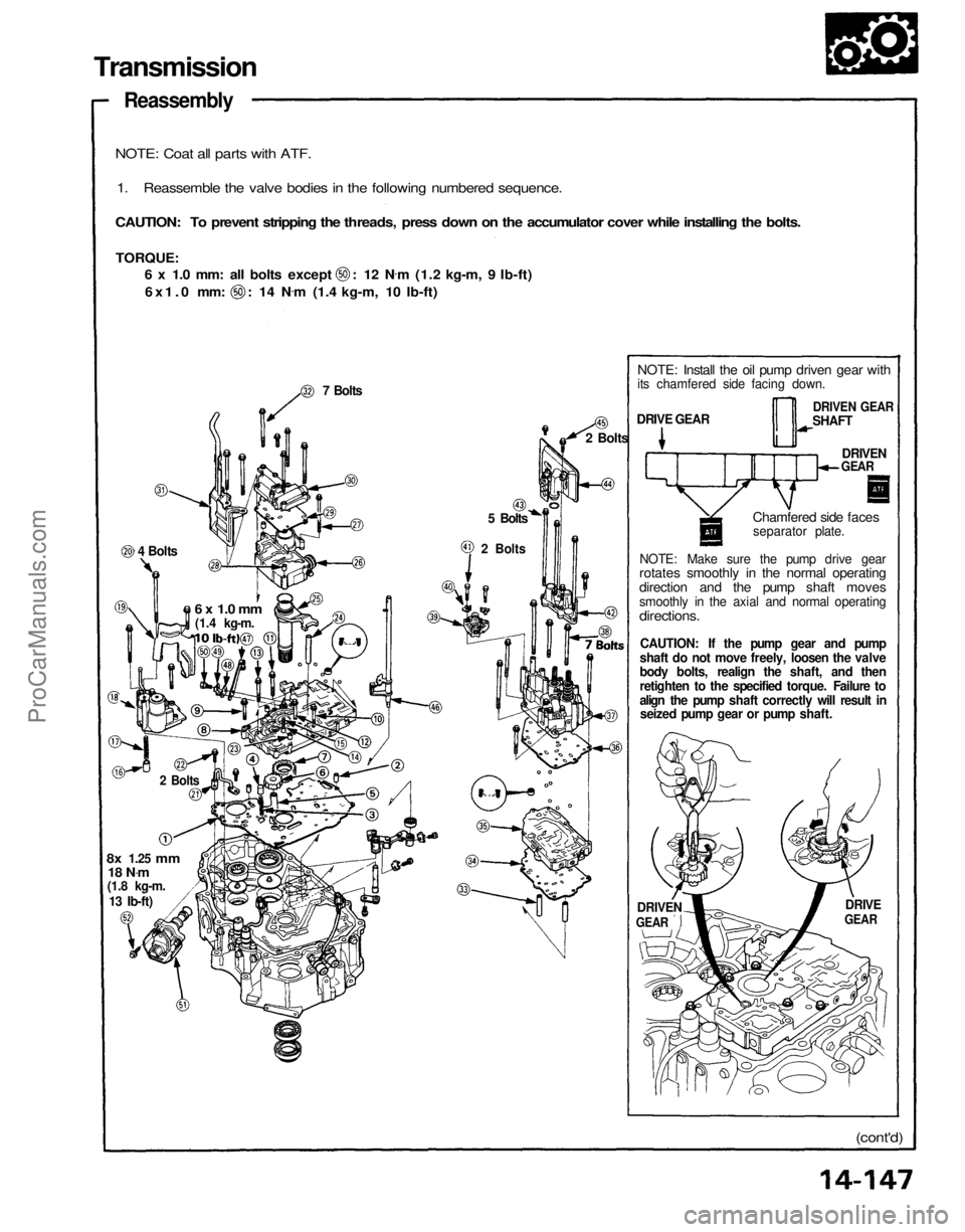
NOTE: Coat all parts with ATF.
1. Reassemble the valve bodies in the following numbered sequence.
CAUTION: To prevent stripping the threads, press down on the accumulator cover while installing the bolts.
TORQUE:
6 x 1.0 mm: all bolts except : 12 N
.
m (1.2 kg-m, 9 Ib-ft)
6x1.0 mm: : 14 N
.
m (1.4 kg-m, 10 Ib-ft)
7 Bolts
2 Bolts
5 Bolts
2 Bolts
4 Bolts
NOTE: Install the oil pump driven gear with
its chamfered side facing down.
NOTE: Make sure the pump drive gear
rotates smoothly in the normal operating
direction and the pump shaft moves
smoothly in the axial and normal operating
directions.
CAUTION: If the pump gear and pump
shaft do not move freely, loosen the valve
body bolts, realign the shaft, and then
retighten to the specified torque. Failure to
align the pump shaft correctly will result in seized pump gear or pump shaft.
DRIVE
GEAR
DRIVEN
(cont'd)
8x
1.25
mm
18 N .
m
(1.8 kg-m.
6 x 1.0 mm
(1.4 kg-m.
2 Bolts
13 Ib-ft)
GEAR
Chamfered side faces
separator plate.
DRIVEN
GEAR
DRIVEN GEAR
SHAFT
DRIVE GEARProCarManuals.com