Page 1332 of 1640

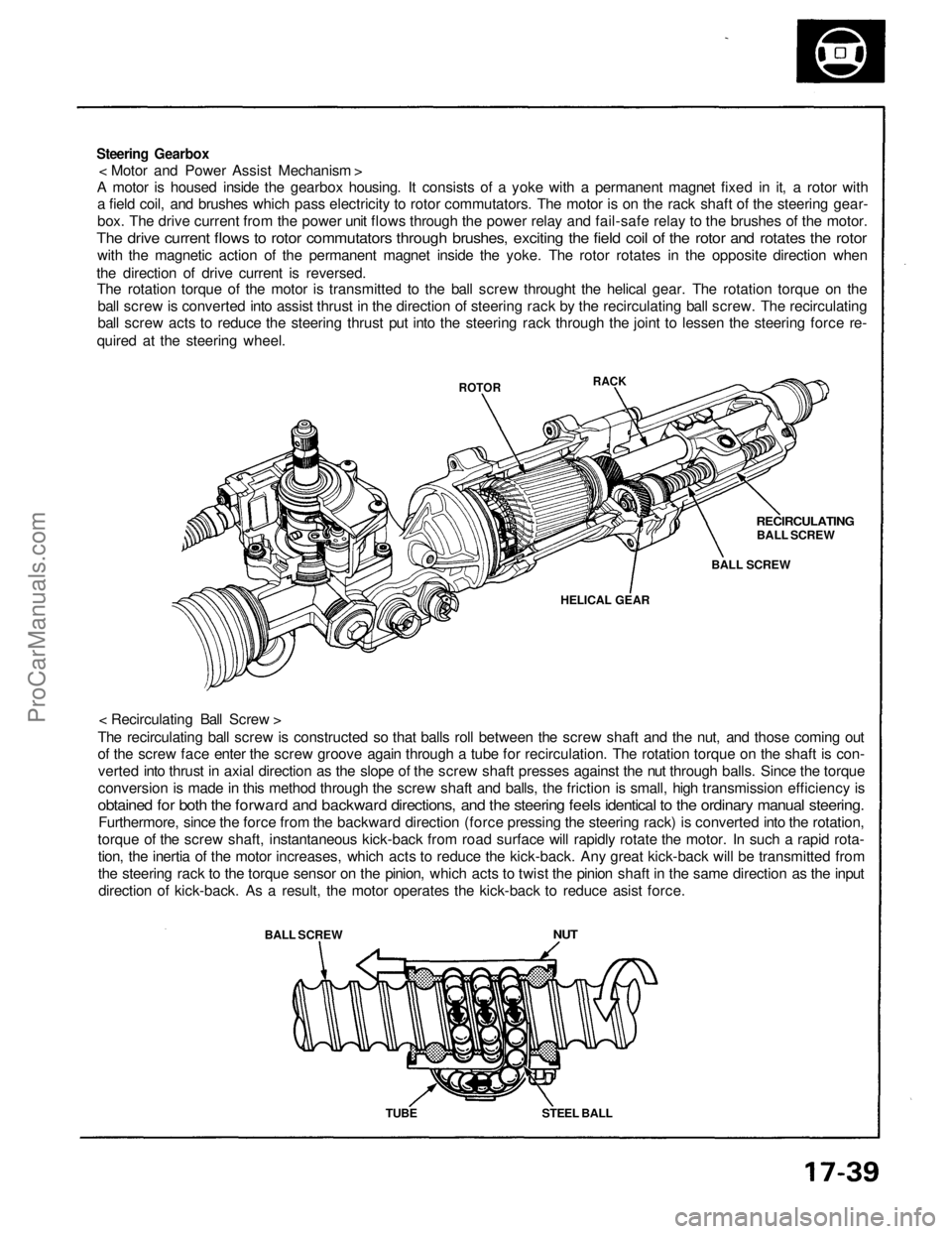
Steering Gearbox
< Motor and Power Assist Mechanism >
A motor is housed inside the gearbox housing. It consists of a yoke with a permanent magnet fixed in it, a rotor with
a field coil, and brushes which pass electricity to rotor commutators. The motor is on the rack shaft of the steering gear-
box. The drive current from the power unit flows through the power relay and fail-safe relay to the brushes of the motor.
The drive current flows to rotor commutators through brushes, exciting the field coil of the rotor and rotates the rotor
with the magnetic action of the permanent magnet inside the yoke. The rotor rotates in the opposite direction when
the direction of drive current is reversed.
The rotation torque of the motor is transmitted to the ball screw throught the helical gear. The rotation torque on the
ball screw is converted into assist thrust in the direction of steering rack by the recirculating ball screw. The recirculating
ball screw acts to reduce the steering thrust put into the steering rack through the joint to lessen the steering force re-
quired at the steering wheel.
< Recirculating Ball Screw >
The recirculating ball screw is constructed so that balls roll between the screw shaft and the nut, and those coming out
of the screw face enter the screw groove again through a tube for recirculation. The rotation torque on the shaft is con-
verted into thrust in axial direction as the slope of the screw shaft presses against the nut through balls. Since the torque
conversion is made in this method through the screw shaft and balls, the friction is small, high transmission efficiency is
obtained for both the forward and backward directions, and the steering feels identical to the ordinary manual steering.
Furthermore, since the force from the backward direction (force pressing the steering rack) is converted into the rotation,
torque of the screw shaft, instantaneous kick-back from road surface will rapidly rotate the motor. In such a rapid rota-
tion, the inertia of the motor increases, which acts to reduce the kick-back. Any great kick-back will be transmitted from
the steering rack to the torque sensor on the pinion, which acts to twist the pinion shaft in the same direction as the input
direction of kick-back. As a result, the motor operates the kick-back to reduce asist force.
BALL SCREW
ROTOR
NUT
TUBE
STEEL BALL
HELICAL GEAR
BALL SCREW
RECIRCULATING
BALL SCREW
RACKProCarManuals.com
Page 1333 of 1640
Wiring Locations
EPS CONTROL UNIT
MAIN RELAY BOX
POWER UNIT
TORQUE SENSOR 6-P CONNECTOR/
STEERING WHEEL SPEED SENSOR
4-P CONNECTOR
STEERING GEARBOX
(TORQUE SENSOR/STEERING WHEEL
SPEED SENSOR)
UNDER-DASH FUSE/RELAY BOX
TRANSMISSION CONTROL MODULE (TCM)
22-P CONNECTOR
VEHICLE SPEED SENSOR
(VSS)
ALTERNATOR 4-P CONNECTOR
EPS INDICATOR LIGHTProCarManuals.com
Page 1334 of 1640
Troubleshooting
Troubleshooting Precautions
Always use the test harness to verify the resistance, voltage, current and other electrical characteristics for the EPS
control unit, torque sensor, steering wheel speed sensor, power unit, and their connectors.
The test probe must not make direct contact with the connector terminals. Make sure that the terminals are not bent or damaged in any way when a test harness is installed.
A digital circuit tester must be used to perform the inspections.
An analog circuit tester must be used only when this procedure is indicated in the specification figures.
The EPS system connector should not be disconnected except when necessary.
Inspect the connection condition and ground of each EPS system connector before peforming the troubleshooting
procedures.ProCarManuals.com
Page 1337 of 1640
Test Harness Installation
Test Harness A
EPS CONTROL UNIT
TEST HARNESS A
07MAZ-SL00100
Test Harness B
TEST HARNESS B
07MAZ-SL00200
STEERING GEARBOX
Test Harness C
POWER UNIT
TEST HARNESS C
07MAZ-SL00300
Power Unit Checker
Connect to the
cigarette lighter
POWER UNIT CHECKER
07MAZ-SL00400
POWER UNIT
OUTPUT
(VIS)
Remove the glove box and disconnect the EPS con-
trol unit connector.
Connect test harness A.
Disconnect the torque sensor and steering speed sen-
sor connectors and connect test harness B. Pull the floor carpet back from the passenger's side
and remove the bass speaker and power unit cover.
Disconnect the connector and connect test harness C.
Pull the floor carpet back from the passenger's side
and remove the bass speaker and power unit cover. Disconnect the connector and connect the power unit
checker.
Remove the cigarette lighter and connect the power
unit checker.ProCarManuals.com
Page 1355 of 1640
7. Tighten the new spindle nut to specified torque,
then stake the spindle nut shoulder against the
spindle.
335 N .
m
(33.5 kg-m, 242 Ib-ft)
Stake
After tightening, use a
drift to stake spindle
nut shoulder against
the spindle.ProCarManuals.com
Page 1481 of 1640

4. A/C Compressor Clutch Relay
When the ECU receives a demand for cooling from the air conditioning system (compressor control unit), it delays
the compressor from being energized, and enriches the mixture to assure smooth transition to the A/C mode.
5. Purge Cut-off Solenoid Valve
When the coolant temperature is below 70 °C (158 °F), the ECU supplies a ground to the purge cut-off solenoid valve
which cuts vacuum to the purge control valve.
6. Chamber Volume Control Solenoid Valve (CVCSV)
When the engine rpm is below 4,800 rpm the CVCSV is activated by a signal from the ECU, intake air flows through
a smaller chamber, then high torque is delivered. At speeds higher than 4,800 rpm, both solenoid valves are deac-
tivated by the ECU, and intake air flows through the a larger chamber in order to increase airflow.
7. EGR Control Solenoid Valve (EGR CSV)
When the EGR is required for control of oxides of nitrogen (NOx) emissions, the ECU supplies ground to the EGR CSV
which supplies regulated vacuum to the EGR valve.
ECU Back-up Functions
1. Fail-Safe Function
When an abnormality occurs in a signal from a sensor, the ECU ignores that signal and assumes a pre-programmed
value that allows the engine to continue to run.
2. Back-up Function
When an abnormality occurs in the ECU itself, the injectors are controlled by a back-up circuit independent of the
system in order to permit minimal diving.
3. Self-diagnosis Function (Check Engine light)
When an abnormality occurs in a signal from a sensor, the ECU lights the Check Engine light and stores the failure
code in erasable memory. When the ignition is initially turned on, the ECU supplies ground for the Check Engine light
for two seconds.ProCarManuals.com
Page 1524 of 1640
Chamber Volume Control System
Description
Satisfactory power performance is achieved by closing and opening the chamber volume control valves. High torque at
low RPM is achieved when the valves are closed, whereas high power at high RPM is achieved by when the valves are
opened.
CHAMBER VOLUME CONTROL SOLENOID
VALVE ON
ENGINE RPM IS ABOVE 4,800 rpm
OPEN
BLK/YEL
To No. 2 FUSE
CLOSE
CHECK
VALVE
VACUUM
TANK
RED/BLU
ECU
CHAMBER
VOLUME
CONTROL
DIAPHRAGM
CHAMBER
VOLUME
CONTROL
VALVE
(cont'd)ProCarManuals.com
Page 1550 of 1640

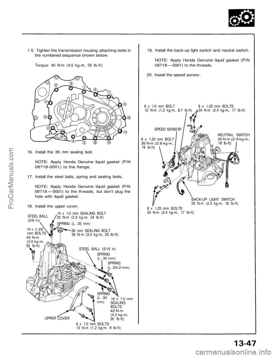
1 5. Tighten the transmission housing attaching bolts in
the numbered sequence shown below.
Torque: 45 N·m (4.5 kg-m, 33 Ib-ft)
16. Install the 36 mm sealing bolt.
NOTE: Apply Honda Genuine liquid gasket (P/N
08718-0001) to the flange.
17. Install the steel balls, spring and sealing bolts.
NOTE: Apply Honda Genuine liquid gasket (P/N
08718 — 0001) to the threads, but don't plug the
hole with liquid gasket.
18. Install the upper cover.
STEEL BALL
(3/8 in)
10 x
1.25
mm BOLTS
45 N·m
(4.5 kg-m,
33 Ib-ft)
14 x 1.0 mm SEALING BOLT
33 N·m (3.3 kg-m, 24 Ib-ft)
SPRING (L. 25 mm)
36 mm SEALING BOLT
35 N·m (3.5 kg-m, 25 Ib-ft)
STEEL BALL (5/16 in)
SPRING
(L. 30 mm)
SPRING
(L.
24.2
mm)
UPPER COVER
19. Install the back-up light switch and neutral switch.
NOTE: Apply Honda Genuine liquid gasket (P/N
08718 — 0001) to the threads.
20. Install the speed sensor.
6 x 1.0 mm BOLT
12 N·m (1.2 kg-m, 8.7 Ib-ft)
SPEED SENSOR
8 x 1.25 mm BOLT
26 N·m
(2.6
kg-m,
19 Ib-ft)
NEUTRAL SWITCH
25 N·m
(2.5
kg-m,
18 Ib-ft)
SPRING
(L. 30
mm)
16 x 1.0 mm
SEALING
BOLTS
42 N·m
(4.2 kg-m,
30 Ib-ft)
6 x 1.0 mm BOLTS
12 N·m (1.2 kg-m. 9 Ib-ft)
8 x 1.25 mm BOLTS
24 N·m (2.4 kg-m, 17 Ib-ft)
8 x 1.25 mm BOLTS
24 N·m (2.4 kg-m, 17 Ib-ft)
BACK-UP LIGHT SWITCH
25 N·m (2.5 kg-m, 18 Ib-ft)ProCarManuals.com