1991 ACURA NSX torque
[x] Cancel search: torquePage 1319 of 1640
Manual Steering
Overhaul (Cont'd)
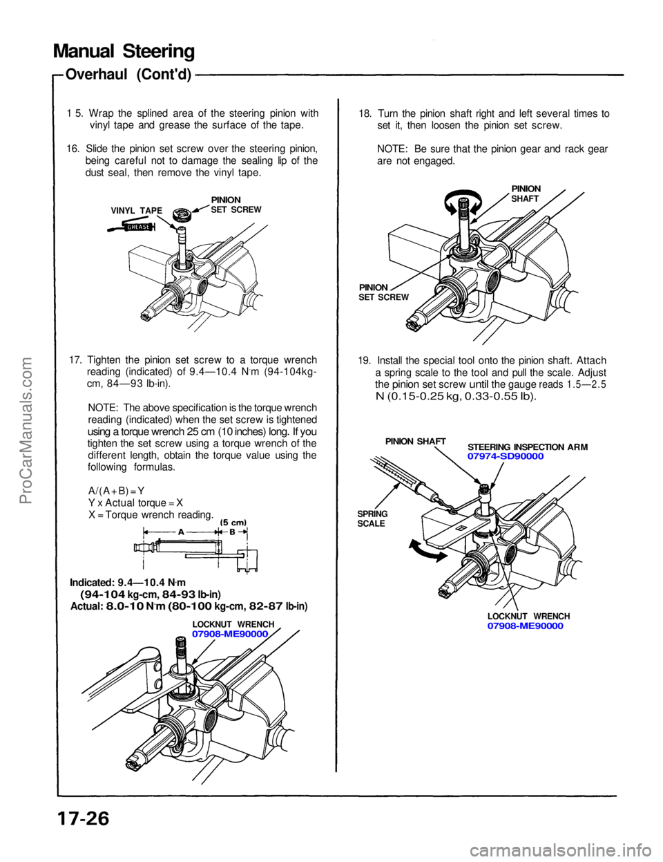
1 5. Wrap the splined area of the steering pinion with vinyl tape and grease the surface of the tape.
16. Slide the pinion set screw over the steering pinion, being careful not to damage the sealing lip of the
dust seal, then remove the vinyl tape.
PINION
SET SCREW
VINYL TAPE
17. Tighten the pinion set screw to a torque wrench reading (indicated) of 9.4—10.4 N.m (94-104kg-
cm, 84—93 Ib-in).
NOTE: The above specification is the torque wrench
reading (indicated) when the set screw is tightened
using a torque wrench 25 cm (10 inches) long. If you
tighten the set screw using a torque wrench of the different length, obtain the torque value using the
following formulas.
A/(A
+ B) = Y
Y x Actual torque = XX = Torque wrench reading.
Indicated: 9.4—10.4 N .
m
(94-104
kg-cm,
84-93
Ib-in)
Actual:
8.0-10
N.m
(80-100
kg-cm,
82-87
Ib-in)
LOCKNUT WRENCH
07908-ME90000
18. Turn the pinion shaft right and left several times to
set it, then loosen the pinion set screw.
NOTE: Be sure that the pinion gear and rack gear
are not engaged.
PINION
SHAFT
PINION
SET SCREW
19. Install the special tool onto the pinion shaft. Attach a spring scale to the tool and pull the scale. Adjust
the
pinion
set
screw
until
the
gauge
reads
1.5—2.5
N (0.15-0.25 kg, 0.33-0.55 Ib).
STEERING INSPECTION ARM
07974-SD90000
PINION SHAFT
SPRING
SCALE
LOCKNUT WRENCH
07908-ME90000ProCarManuals.com
Page 1325 of 1640
FUSE BOX
System Description
Major Components
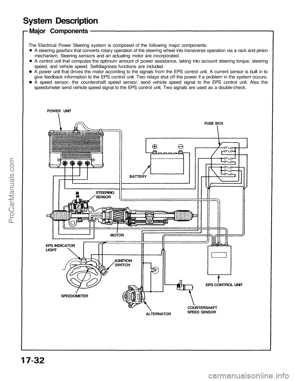
The Electrical Power Steering system is composed of the following major components:
EPS CONTROL UNIT
COUNTERSHAFT
SPEED SENSOR
ALTERNATOR
SPEEDOMETER
EPS INDICATOR
LIGHT
STEERING
SENSOR
BATTERY
POWER UNIT
MOTOR
IGNITION
SWITCH
A steering gearbox that converts rotary operation of the steering wheel into transverse operation via a rack and pinion
mechanism. Steering sensors and an actuating motor are incorporated.
A control unit that computes the optimum amount of power assistance, taking into account steering torque, steering
speed, and vehicle speed. Selfdiagnosis functions are included.
A power unit that drives the motor according to the signals from the EPS control unit. A current sensor is built in to
give feedback information to the EPS control unit. Two relays shut off the power if a problem in the system occurs.
A speed sensor, the countershaft speed sensor, send vehicle speed signal to the EPS control unit. Also the
speedometer send vehicle speed signal to the EPS control unit. Two signals are used as a double-check.ProCarManuals.com
Page 1326 of 1640
System Operation
Manual Steering Operation
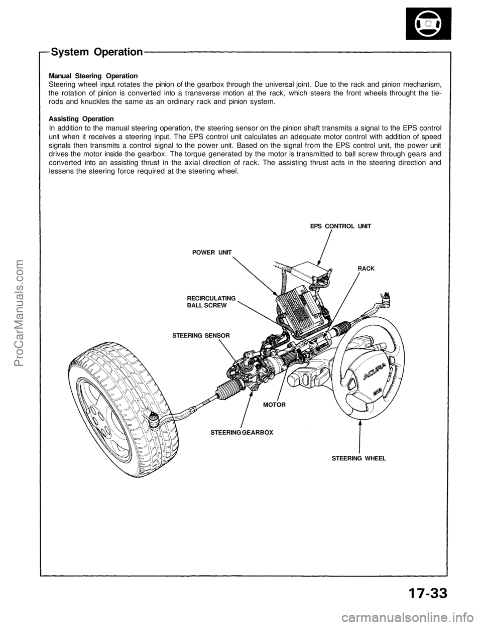
Steering wheel input rotates the pinion of the gearbox through the universal joint. Due to the rack and pinion mechanism,
the rotation of pinion is converted into a transverse motion at the rack, which steers the front wheels throught the tie-
rods and knuckles the same as an ordinary rack and pinion system.
Assisting Operation
In addition to the manual steering operation, the steering sensor on the pinion shaft transmits a signal to the EPS control
unit when it receives a steering input. The EPS control unit calculates an adequate motor control with addition of speed
signals then transmits a control signal to the power unit. Based on the signal from the EPS control unit, the power unit
drives the motor inside the gearbox. The torque generated by the motor is transmitted to ball screw through gears and
converted into an assisting thrust in the axial direction of rack. The assisting thrust acts in the steering direction and
lessens the steering force required at the steering wheel.
POWER UNIT
RECIRCULATING
BALL SCREW
STEERING SENSOR
STEERING GEARBOX
MOTOR
STEERING WHEEL
RACK
EPS CONTROL UNITProCarManuals.com
Page 1327 of 1640
System Description
Function and Operation
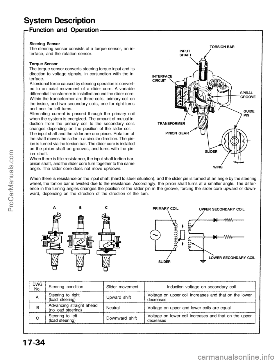
Steering Sensor
The steering sensor consists of a torque sensor, an in-
terface, and the rotation sensor.
INPUT
SHAFT
TORSION BAR
SPIRAL
GROOVE
GUIDE
PIN
INTERFACE
CIRCUIT
Torque Sensor
The torque sensor converts steering torque input and its
direction to voltage signals, in conjunction with the in-
terface.
A torsional force caused by steering operation is convert-
ed to an axial movement of a slider core. A variable
differential transformer is installed around the slider core.
Within the tranceformer are three coils, primary coil on
the inside, and two secondary coils, one for right turns
and one for left turns.
Alternating current is passed through the primary coil
when the system is energized. The amount of mutual in-
duction from the primary coil to the secondary coils
changes depending on the position of the slider coil.
The input shaft and the slider are one piece. Rotation of
the shaft moves the slider in a circular direction. The pin-
ion is turned via the torsion bar. The slider core is installed
on the pinion shaft on grooves, and turns with the pin-
ion shaft.
When there is little resistance, the input shaft tortion bar,
pinion shaft, and the slider core turn together to the same
angle. The slider core does not move up/down.
When there is resistance on the input shaft (hard to steer situation), and the slider pin is turned at an angle by the steering
wheel, the tortion bar is twisted due to the resistance. Accordingly, the pinion shaft turns at a smaller angle. The differ-
ence in the turning angles changes the position of the slider pin in the groove, forcing the slider core upward or down-
ward, depending on the direction of the direction of the turn.
TRANSFORMER
PINION GEAR
SLIDER
WING
PRIMARY COIL
UPPER SECONDARY COIL
LOWER SECONDARY COIL
SLIDER
DWG
No.
A
B
C
Steering condition
Steering to right
(load steering)
Advancing straight ahead
(no load steering)
Steering to left
(load steering)
Slider movement
Upward shift
Neutral
Downward shift
Induction voltage on secondary coil
Voltage on upper coil increases and that on the lower
decreases
Voltage on upper and lower coils are equal
Voltage on lower coil increases and that on the upper
decreasesProCarManuals.com
Page 1328 of 1640
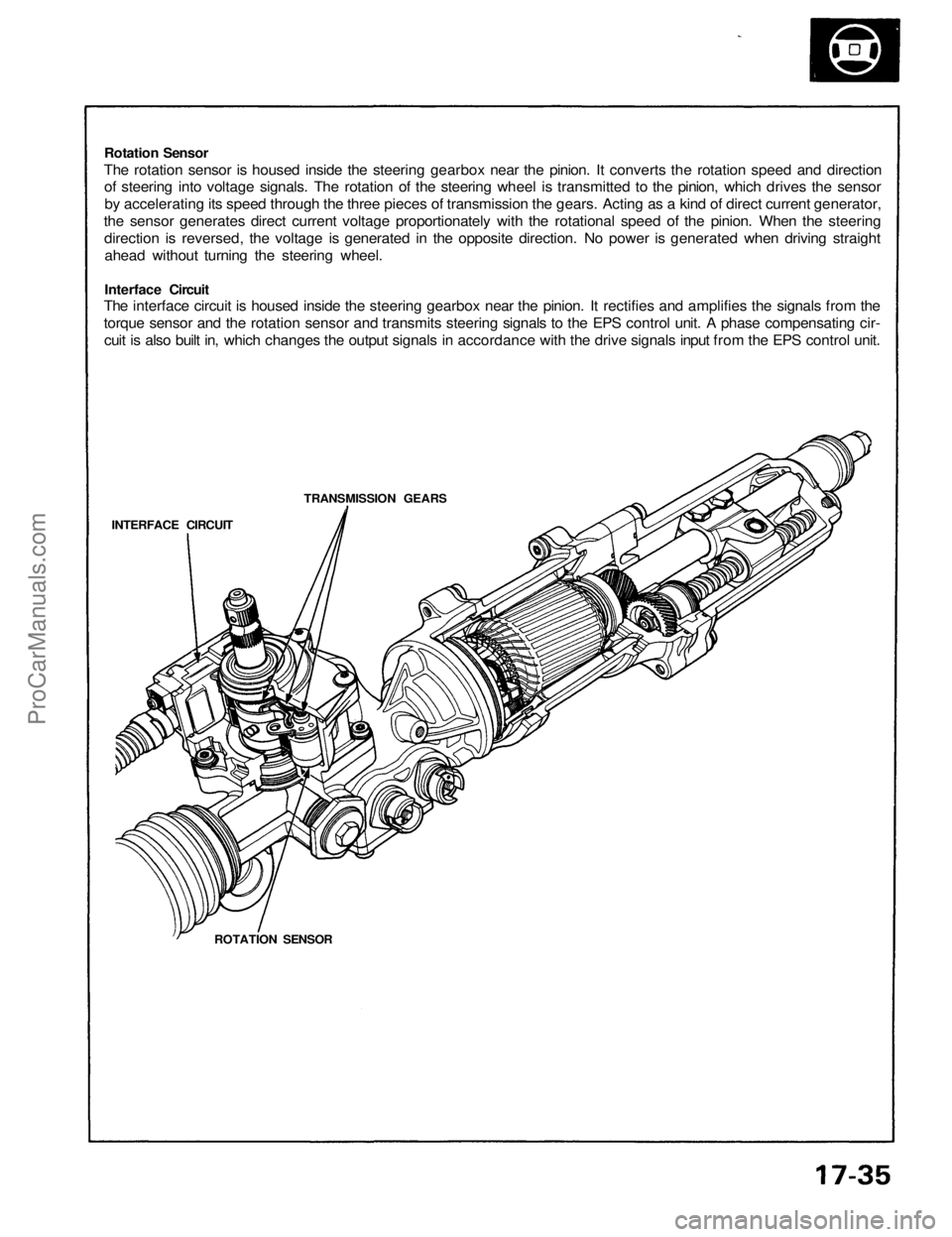
Rotation Sensor
The rotation sensor is housed inside the steering gearbox near the pinion. It converts the rotation speed and direction
of steering into voltage signals. The rotation of the steering wheel is transmitted to the pinion, which drives the sensor
by accelerating its speed through the three pieces of transmission the gears. Acting as a kind of direct current generator,
the sensor generates direct current voltage proportionately with the rotational speed of the pinion. When the steering
direction is reversed, the voltage is generated in the opposite direction. No power is generated when driving straight
ahead without turning the steering wheel.
Interface Circuit
The interface circuit is housed inside the steering gearbox near the pinion. It rectifies and amplifies the signals from the
torque sensor and the rotation sensor and transmits steering signals to the EPS control unit. A phase compensating cir-
cuit is also built in, which changes the output signals in accordance with the drive signals input from the EPS control unit.
TRANSMISSION GEARS
INTERFACE CIRCUIT
ROTATION SENSORProCarManuals.com
Page 1329 of 1640
System Description
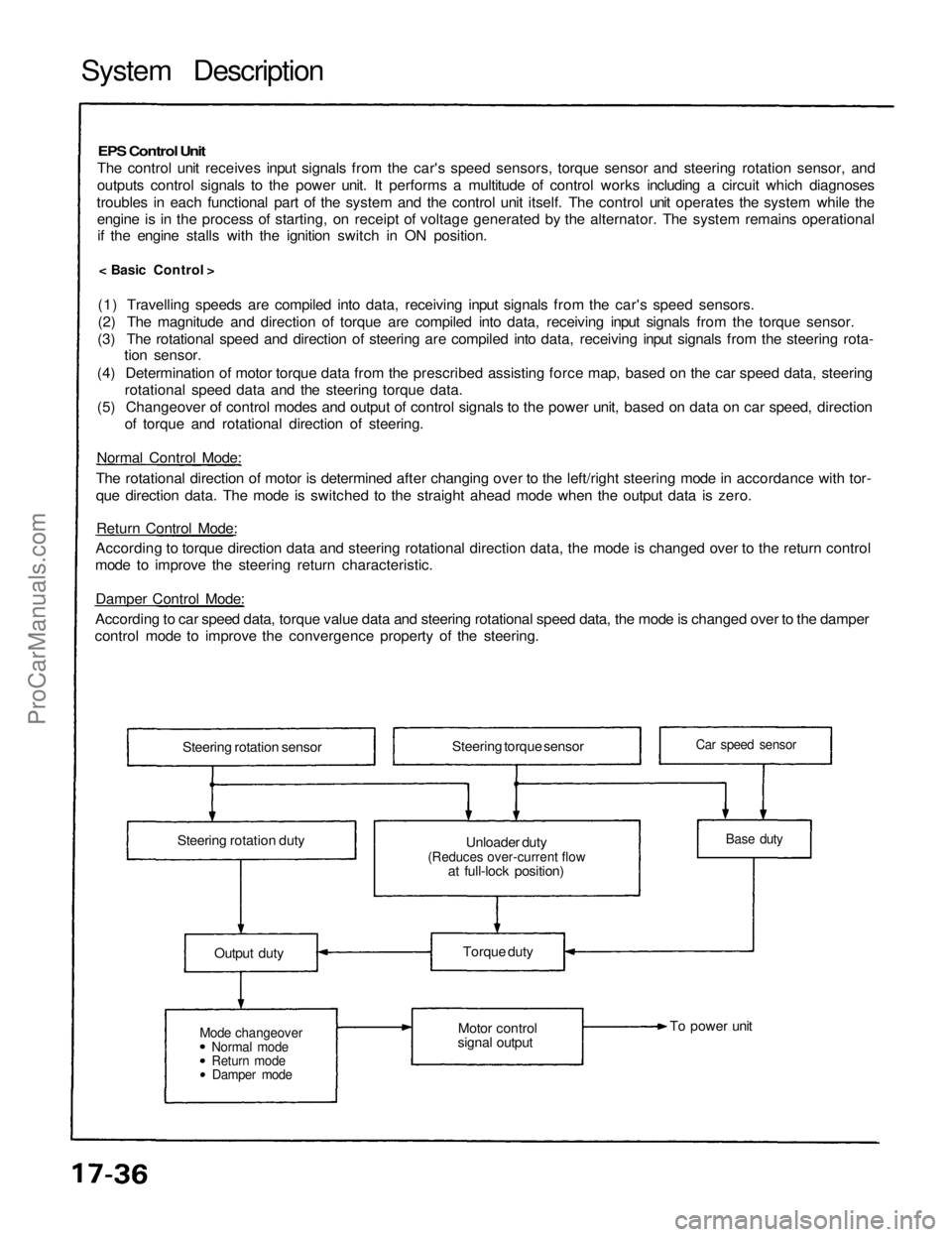
EPS Control Unit
The control unit receives input signals from the car's speed sensors, torque sensor and steering rotation sensor, and
outputs control signals to the power unit. It performs a multitude of control works including a circuit which diagnoses
troubles in each functional part of the system and the control unit itself. The control unit operates the system while the engine is in the process of starting, on receipt of voltage generated by the alternator. The system remains operationalif the engine stalls with the ignition switch in ON position.
< Basic Control >
(1) Travelling speeds are compiled into data, receiving input signals from the car's speed sensors.
(2) The magnitude and direction of torque are compiled into data, receiving input signals from the torque sensor.
(3) The rotational speed and direction of steering are compiled into data, receiving input signals from the steering rota- tion sensor.
(4) Determination of motor torque data from the prescribed assisting force map, based on the car speed data, steering rotational speed data and the steering torque data.
(5) Changeover of control modes and output of control signals to the power unit, based on data on car speed, direction of torque and rotational direction of steering.
Normal Control Mode:
The rotational direction of motor is determined after changing over to the left/right steering mode in accordance with tor-
que direction data. The mode is switched to the straight ahead mode when the output data is zero.
Return Control Mode:
According to torque direction data and steering rotational direction data, the mode is changed over to the return control
mode to improve the steering return characteristic.
Damper Control Mode:
According to car speed data, torque value data and steering rotational speed data, the mode is changed over to the damper
control mode to improve the convergence property of the steering.
Steering rotation sensor
Steering rotation duty Steering torque sensor
Unloader duty
(Reduces over-current flow
at full-lock position)
Output duty
Mode changeover
Normal mode
Return mode
Damper mode
Torque duty
Motor control
signal output To power unit
Base duty
Car speed sensorProCarManuals.com
Page 1330 of 1640
Self-Diagnosis Function
The EPS control unit monitors the system inputs and outputs, and the driving current of the motor. If there is a problem
in the system, the control unit turns the system off by actuating the relay in the power unit. Power assist stops and
normal manual steering operation resumes. The control unit also turns the EPS indicator light on to alert the driver, and
memorizes the problem in the form of a code. Connecting the terminals of the service check connector with a jumper
wire enables the EPS indicator light to blink the problem code when the ignition switch is turned on.
Unloader Control
If the steering wheel is turned fully and held in the full-lock position, the steering torque reaches the maximum point,
and an over-current flows to the motor and the power unit. The control unit detects this and reduces the current flow
to the motor.
Average Moving Current Control
The electric current flow to the motor is estimated from the current values detected by the current sensor, and the aver-
age current is obtained at two second intervals. The motor driving current is suppressed when the average current value
exceeds a predetermined marginal value. The control unit regurates the motor current during continuous loading to sup-
press any excessive temperature rise in the power unit and the motor.
Over-Voltage Control
If there is an excessive increase in power source voltage due to a poor battery condition, an alternator voltage regulator
problem, etc., the motor assisting force increases, resulting in excessive control. To prevent this, the control unit signals
to the power unit are corrected to ensure that adequate assisting force is generated.ProCarManuals.com
Page 1331 of 1640
System Description
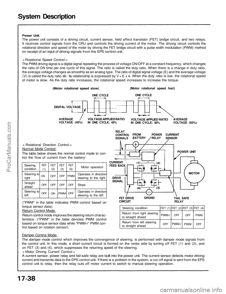
Power Unit
The power unit consists of a driving circuit, current sensor, field effect transistor (FET) bridge circuit, and two relays.
It receives control signals from the CPU and controls the driving current of the motor. The driving circuit controls the
rotational direction and speed of the motor by driving the FET bridge circuit with a pulse width modulation (PWM) method
on receipt of an input of driving signals from the EPS control unit.
< Rotational Speed Control >
The PWM driving signal is a digital signal repeating the process of voltage ON/OFF at a constant frequency, which changes the ratio of ON time per one cycle of this signal. The ratio is called the duty ratio. When there is a change in duty ratio,
the average voltage changes as smoothly as an analog type. The ratio of digital signal voltage (E) and the average voltage
(Motor rotational speed fast)
ONE CYCLE
AVERAGE
VOLTAGE (60%)
VOLTAGE APPLIED RATIO
IN ONE CYCLE: 60%
CURRENT
SENSOR
POWER
RELAY
FROM
BATTERY
RELAY
CONTROL
SIGNALS
VOLTAGE APPLIED RATIO
IN ONE CYCLE: 40%
AVERAGE
VOLTAGE (40%)
(Motor rotational speed slow)
DIGITAL VOLTAGE
ONE CYCLE
CURRENT
FEED BACK
DRIVE
SIGNAL
< Rotational Direction Control >
Normal Mode Control:
The table below shows the normal control mode to con-
trol the flow of current from the battery:
("PWM" in the table indicates PWM control based on
torque sensor data). Return Control Mode:
Return control mode improves the steering return charac-
teristics. ("PWM" in the table denotes PWM control based on torque sensor data while "PWM-r" PWM con-
trol based on rotation sensor).
POWER UNIT
FET DRIVE
CIRCUIT
GROND
FAIL SAFE
RELAY
Damper Control Mode:
The damper mode control which improves the convergence of steering, is performed with damper mode signals from
the control unit. In this mode, a short current circuit is formed on the motor side by turning off FET (1) and (2), and on FET (3) and (4), which suppresses the returning speed of the steering. < Motor Driving Current Control >
A current sensor, power relay and fail-safe relay are built into the power unit. The current sensor detects motor driving
current and transmits data to the EPS control unit. If there is a problem in the system, a cut-off signal is sent from the EPS
control unit to relay, then the relay cuts off motor current to switch to manual steering operation. (V) is called the duty ratio
of motor is slow. As the duty ratio increases, the rotational speed increases to increase the torque. When the duty ratio is low, the rotational speed
Its relationship is expressed by V = E x
Steering
condition Steering to
rightStraight
ahead
Steering to
left
OFFOFF
ON
FET
(1)
FET
(2)
FET
(3)
FET
(4)
OFF
OFF
OFF
ON
OFF
PWM
OFF
OFF
PWM
Motor operation
Stops
Operates in direction
steering to the left Operates in direction
steering to the right
Steering condition
Return from right steering
to straight ahead
Return from left steering
to straight ahead
FET (1)
PWM-r
OFF
FET (2)
OFF
PWM-r
FET (3)
OFF
PWM
OFF
PWM
FET (4)
MOTORProCarManuals.com