Page 1281 of 1640
NOTE: Torque bolts to 55 N
.
m (5.5 kg-m, 40 Ib-ft) in order of thru in
two or more steps. NOTE: Align the control
shaft spring pin with the
groove in the transmission housing.
6x 1.0 mm
12 N .
m
(1.2 kg-m. 9 Ib-ft)
Replace.
Replace.
6 x 1.0 mm
14 N .
m
(1.4
kg-m.
10 Ib-ft)
17 Bolts
10 x 1.25mm
55 N .
m
(5.5 kg-m, 40 Ib-ft)
FORK BOLT HOLE
Turn valve stem so large
chamfered hole faces
fork bolt hole.
SHIFT FORK
MAINSHAFT
COUNTERSHAFT
NOTE: Install the three shafts
Transmission
Reassembly (cont'd)
2. Assemble the transmission housing in the following numbered sequence.
NOTE: See page 14-145 when installing the reverse idler gear.
SECONDARY
SHAFT
together.ProCarManuals.com
Page 1283 of 1640
Transmission
Reassembly (cont'd)
8. Install a new conical spring washers and new locknuts on each shaft.
CAUTION: Install the conical spring washers in the
direction shown.
COUNTERSHAFT LOCKNUT
Left-hand threads
CONICAL SPRING
WASHERS
NOTE: Install in this
direction.
Left-hand threads
MAINSHAFT
LOCKNUT
SECONDARY
SHAFT
LOCKNUT
9. Tighten the locknuts to specified torque.
TORQUE: 140 N .
m (14.0 kg-m, 101 Ib-ft)
NOTE: Countershaft locknut has left-hand
threads.
TORQUE WRENCH
10. Stake each locknut into its shaft, using a 3.5 mm
punch.
COUNTERSHAFT
LOCKNUT
MAINSHAFT
LOCKNUT
SECONDARY
SHAFT
LOCKNUT
11. Install the feed pipes and ball bearing in the left side cover, aligning the lugs of the 1st and 1st-hold
clutch feed pipes with the grooves of the left side
cover.
12. Install the snap ring.
BALL BEARING
markProCarManuals.com
Page 1284 of 1640
LINEAR SOLENOID
6 x 1.0 mm
10 N .
m(1.0 kg-m, 7 Ib-ft)
MAINSHAFT SPEED SENSOR
SPEED SENSOR
COVER
LINEAR
SOLENOID
SHIM
COUNTERSHAFT
SPEED
LOCK WASHER
6 x 1.0 mm
(1.4 kg-m, 10 Ib-ft)
SPEED
SENSOR
COUNTERSHAFT
Install the countershaft speed sensor with the
countershaft speed sensor washer. The main-
shaft speed sensor has no washer.
See page 14-81 thru 82, when installing the
linear solenoid.
NOTE:
13. Install the countershaft and mainshaft speed sen-
sors, vehicle speed sensor cover and linear sole-
noid.
TORQUE: 12 N .
m (1.2 kg-m, 9 Ib-ft)
CONTROL SHAFT
CHANGE SHAFT
CHANGE SHAFT CAP
6x
1.0mm
12 N
.
m (1.2 kg-m, 9 Ib-ft)
CONTROL
LEVER
14. Install the control lever, new lock washers, change
shaft and change shaft cap on the other end of the
control shaft. Tighten the bolts and then bend the tab
over against the bolt head.
12. Install the left side cover.
TORQUE: 12 N .
m (1.2 kg-m, 9 Ib-ft)
SENSOR
WASHER
14 N
.
mProCarManuals.com
Page 1285 of 1640
Torque Converter
Disassembly
6 x 1.0 mm
12 N .
m(1.2 Kg-m. 9 Ib-ft)
DRIVE PLATE
Inspect for cracks.
RING GEAR/TORQUE
CONVERTER ASSEMBLY
WASHER
12 x
1.0mm
75 N .
m (7.5 Kg-m, 54 Ib-ft)
Torque in crisscross pattern.
O-RING
Replace.ProCarManuals.com
Page 1286 of 1640

Transmission
Installation
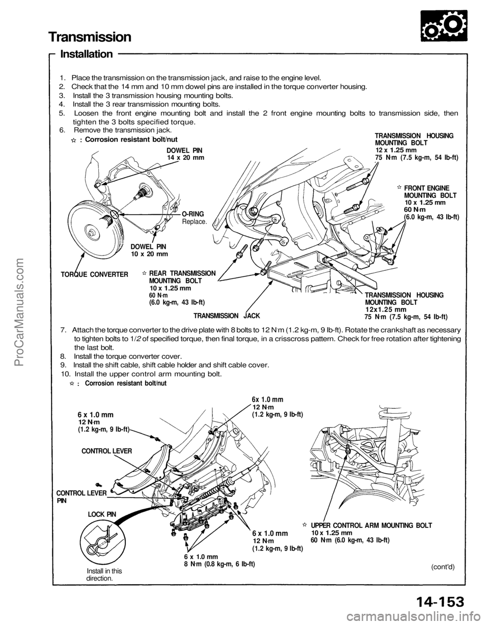
1. Place the transmission on the transmission jack, and raise to the engine level.
2. Check that the 14 mm and 10 mm dowel pins are installed in the torque converter housing.
3. Install the 3 transmission housing mounting bolts.
4. Install the 3 rear transmission mounting bolts.
5. Loosen the front engine mounting bolt and install the 2 front engine mounting bolts to transmission side, then
tighten the 3 bolts specified torque.
TRANSMISSION HOUSINGMOUNTING BOLT
12 x
1.25
mm
75 N .
m (7.5 kg-m, 54 Ib-ft)
DOWEL PIN
14 x 20 mm
FRONT ENGINE
MOUNTING BOLT
10 x
1.25
mm
60 N .
m
(6.0 kg-m, 43 Ib-ft)
TRANSMISSION HOUSING MOUNTING BOLT
12x1.25 mm
75 N .
m (7.5 kg-m, 54 Ib-ft)
O-RING
Replace.
DOWEL PIN
10 x 20 mm
TORQUE CONVERTER REAR TRANSMISSION
MOUNTING BOLT
10 x
1.25
mm
60 N·m
(6.0 kg-m, 43 Ib-ft)
TRANSMISSION JACK
7. Attach the torque converter to the drive plate with 8 bolts to 12 N.m (1.2 kg-m, 9 Ib-ft). Rotate the crankshaft as necessary to tighten bolts to 1/2 of specified torque, then final torque, in a crisscross pattern. Check for free rotation after tighteningthe last bolt.
8. Install the torque converter cover. 9. Install the shift cable, shift cable holder and shift cable cover.
10. Install the upper control arm mounting bolt.
6x 1.0 mm
12 N
.
m
(1.2 kg-m, 9 Ib-ft)
6 x 1.0 mm
12 N
.
m
(1.2 kg-m, 9 Ib-ft)
CONTROL LEVER
UPPER CONTROL ARM MOUNTING BOLT
10 x
1.25
mm
60 N .
m (6.0 kg-m, 43 Ib-ft)
6 x 1.0 mm
12 N
.
m
(1.2 kg-m, 9 Ib-ft)
(cont'd)
6 x 1.0 mm
8 N
.
m (0.8 kg-m, 6 Ib-ft)
Install in this
direction.
LOCK PIN
CONTROL LEVER
PIN
Corrosion resistant bolt/nut
Corrosion resistant bolt/nut
6. Remove the transmission jack.ProCarManuals.com
Page 1289 of 1640

Transmission
Installation (cont'd)
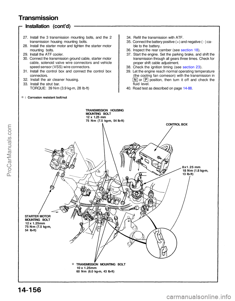
27. Install the 3 transmission mounting bolts, and the 2 transmission housing mounting bolts.
28. Install the starter motor and tighten the starter motor mounting bolts.
29. Install the ATF cooler.
30. Connect the transmission ground cable, starter motor cable, solenoid valve wire connectors and vehicle
speed sensor (VSS) wire connectors.
31. Install the control box and connect the control box connectors.
32. Install the air cleaner housing.
33. Install the strut bar.
TORQUE: 39 N .
m (3.9 kg-m, 28 Ib-ft)
Corrosion resistant bolt/nut 34. Refill the transmission with ATF.
35. Connect the battery positive (+) and negative (-) ca- ble to the battery.
36. Inspect the rear camber (see section 18).
37. Start the engine. Set the parking brake, and shift the transmission through all gears three times. Check forproper shift cable adjustment.
38. Check the ignition timing (see section 23).
39. Let the engine reach normal operating temperature (the cooling fan comeson) with the transmission in or position, then turn it off and check the
fluid level.
40. Road test as described on page 14-88.
TRANSMISSION HOUSING MOUNTING BOLT
12 x
1.25
mm
75 N .
m (7.5 kg-m, 54 Ib-ft)
CONTROL BOX
8x1.25 mm
18 N .
m
(1.8 kg-m,
13 Ib-ft)
TRANSMISSION MOUNTING BOLT
10 x 1.25mm
60 N .
m (6.0 kg-m, 43 Ib-ft)
STARTER MOTOR
MOUNTING BOLT
12 x 1.25mm
75 N .
m
(7.5 kg-m,
54 Ib-ft)ProCarManuals.com
Page 1308 of 1640

Installation
CAUTION:
All SRS wiring harnesses are covered with yellow
outer insulation.
Replace the entire affected SRS harness assembly if
it has an open circuit or damaged wiring.
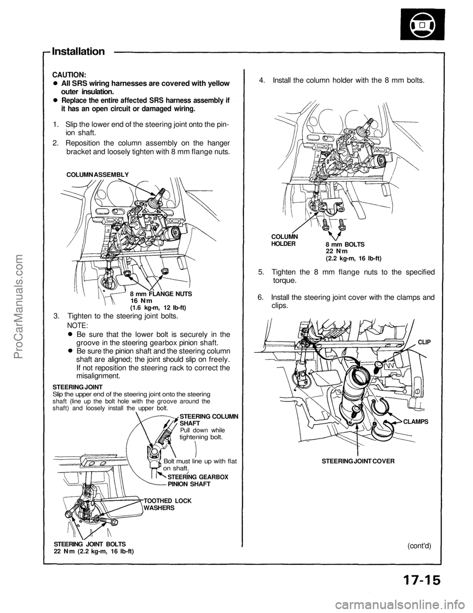
1. Slip the lower end of the steering joint onto the pin- ion shaft.
2. Reposition the column assembly on the hanger bracket and loosely tighten with 8 mm flange nuts.
COLUMN ASSEMBLY
8 mm FLANGE NUTS
16 N.m
(1.6 kg-m, 12 lb-ft)
3. Tighten to the steering joint bolts.
NOTE:
Be sure that the lower bolt is securely in the
groove in the steering gearbox pinion shaft. Be sure the pinion shaft and the steering column
shaft are aligned; the joint should slip on freely.
If not reposition the steering rack to correct the
misalignment.
STEERING JOINT
Slip the upper end of the steering joint onto the steering
shaft (line up the bolt hole with the groove around the
shaft) and loosely install the upper bolt. STEERING COLUMN
SHAFTPull down while
tightening bolt.
Bolt must line up with flat
on shaft.
STEERING GEARBOX
PINION SHAFT
TOOTHED LOCK
WASHERS
STEERING JOINT BOLTS
22 N ·
m (2.2 kg-m, 16 Ib-ft) 4. Install the column holder with the 8 mm bolts.
COLUMN
HOLDER
8 mm BOLTS
22 N.m
(2.2 kg-m, 16 Ib-ft)
5. Tighten the 8 mm flange nuts to the specified
torque.
6. Install the steering joint cover with the clamps and clips.
CLIP
STEERING JOINT COVER
CLAMPS
(cont'd)ProCarManuals.com
Page 1313 of 1640

Manual Steering
Gearbox Removal/Installation (Cont'd)
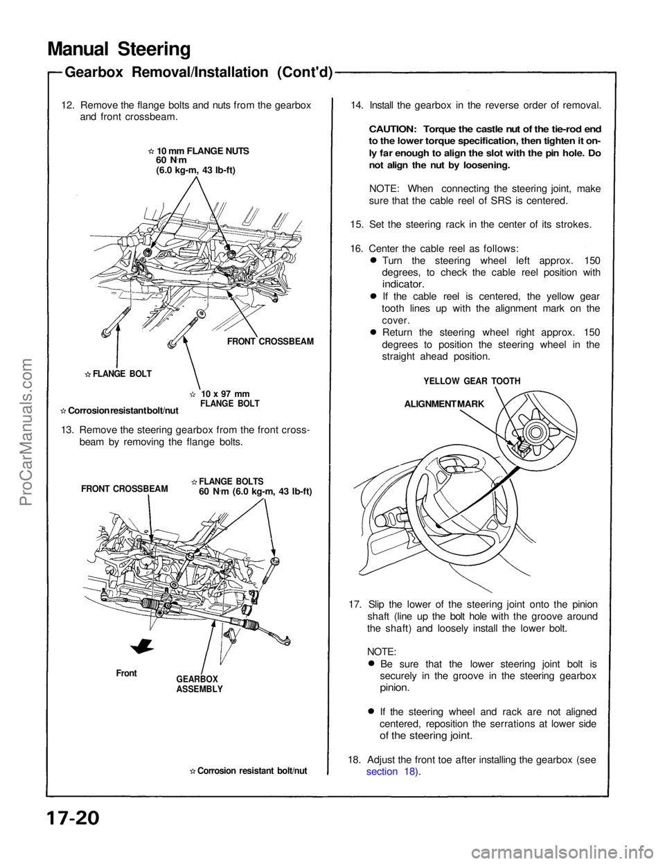
12. Remove the flange bolts and nuts from the gearbox and front crossbeam.
10 mm FLANGE NUTS
60 N ·
m
(6.0 kg-m, 43 Ib-ft)
FRONT CROSSBEAM
10 x 97 mm
FLANGE BOLT
FLANGE BOLT
Corrosion resistant bolt/nut
13. Remove the steering gearbox from the front cross- beam by removing the flange bolts.
FLANGE BOLTS
60 N.
m (6.0 kg-m, 43 Ib-ft)
FRONT CROSSBEAM
Front
GEARBOX
ASSEMBLY
Corrosion resistant bolt/nut
14. Install the gearbox in the reverse order of removal.
CAUTION: Torque the castle nut of the tie-rod end
to the lower torque specification, then tighten it on-
ly far enough to align the slot with the pin hole. Do
not align the nut by loosening.
NOTE: When connecting the steering joint, make
sure that the cable reel of SRS is centered.
15. Set the steering rack in the center of its strokes.
16. Center the cable reel as follows: Turn the steering wheel left approx. 150
degrees, to check the cable reel position with
indicator.
If the cable reel is centered, the yellow gear
tooth lines up with the alignment mark on the
cover.
Return the steering wheel right approx. 150
degrees to position the steering wheel in the
straight ahead position.
YELLOW GEAR TOOTH
ALIGNMENT MARK
17. Slip the lower of the steering joint onto the pinion shaft (line up the bolt hole with the groove around
the shaft) and loosely install the lower bolt.
NOTE:
Be sure that the lower steering joint bolt is
securely in the groove in the steering gearbox
pinion.
If the steering wheel and rack are not aligned
centered, reposition the serrations at lower side
of the steering joint.
18. Adjust the front toe after installing the gearbox (see section 18).ProCarManuals.com