Page 156 of 1640
28. Tighten bolts and nuts finger tight at six points as
shown below.
29. Starting with nut torque all bolts and nuts, in a
clockwise pattern in three steps.
NOTE: Excessive tightening can cause distortion of
oil pan gasket and oil leakage.
Torque: 14 N-m (1.4 kg-m, 10 lb-ft)ProCarManuals.com
Page 274 of 1640
Intake Air System
Intake Air Bypass (IAB) Control System
Description
Satisfactory power performance is achieved by closing and opening the intake air bypass (IAB) control valves. High torque
at low engine speed is achieved when the valves are closed, whereas high power at high engine speed is achieved when
the valves are opened.
INTAKE AIR BYPASS (IAB) CONTROL
SOLENOID VALVE ON
ENGINE SPEED IS ABOVE 4,800 rpm
OPEN: HIGH ENGINE SPEED
IAB CONTROL
SOLENOID
VALVE
To No. 5 BACK-UP LIGHTS
ALTERNATOR TURN SIGNALS
(15 A) FUSE
IAB
CONTROL
DIAPHRAGM
IAB
CONTROL
VALVE
CLOSED: LOW ENGINE SPEEDProCarManuals.com
Page 299 of 1640
6. Install the release bearing on the pressure plate.
7. Install the pressure plate.
NOTE:
Align the mark on the mid plate with the mark onthe pressure plate.
After installing, make sure the release bearing is
secure.
Align the marks.
PRESSURE PLATE
RELEASE BEARING
PRESSURE PLATE
(P/N 08798-9002)
RELEASE
BEARING
Place the diaphragm spring fingers
in the groove of the release bearing.
9. Remove the special tools.
10. Initialize the mid plate guides (see page 12-14
('93-'96), 12-16 ('91-'92 Models).
MOUNTING BOLT
8 x
1.25
mm
22 N·m (2.2 kg-m, 16 Ib-ft)
8. Torque the mounting bolts in a crisscross pattern
as shown. Tighten them several steps to prevent
warping the diaphragm spring.
NOTE: Place the diaphragm spring fingers in the
groove of the release bearing.ProCarManuals.com
Page 346 of 1640

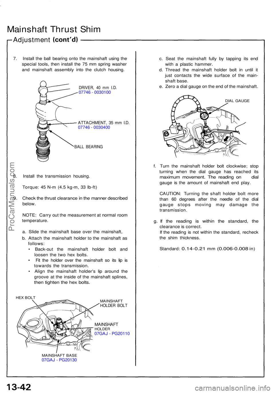
Mainshaft Thrus t Shi m
Adjustmen t
7. Instal l th e bal l bearin g ont o th e mainshaf t usin g th e
specia l tools , the n instal l th e 7 5 m m sprin g washe r
an d mainshaf t assembl y int o th e clutc h housing .
DRIVER, 4 0 m m I.D .07746 - 0030100
ATTACHMENT , 3 5 m m I.D .07746 - 0030400
BAL L BEARIN G
8. Instal l th e transmissio n housing .
Torque : 4 5 N- m (4. 5 kg-m , 3 3 Ib-ft )
9. Chec k th e thrus t clearanc e in th e manne r describe d
below.
NOTE : Carr y ou t th e measuremen t a t norma l roo m
temperature .
a . Slid e th e mainshaf t bas e ove r th e mainshaft ,
b . Attac h th e mainshaf t holde r t o th e mainshaf t a s
follows :
• Back-ou t th e mainshaf t holde r bol t an d
loose n th e tw o he x bolts .
• Fi t th e holde r ove r th e mainshaf t s o it s li p i s
toward s th e transmission .
• Alig n th e mainshaf t holder' s li p aroun d th e
groov e a t th e insid e of the mainshaf t splines ,
then tighte n th e he x bolts .
HEX BOL T
MAINSHAFT
HOLDER BOL T
MAINSHAF THOLDER07GAJ - PG20110
MAINSHAF T BAS E07GAJ - PG20130
c. Sea t th e mainshaf t full y b y tappin g it s en d
wit h a plasti c hammer .
d . Threa d th e mainshaf t holde r bol t i n unti l i t
jus t contact s th e wid e surfac e o f th e main -
shaf t base .
e . Zer o a dia l gaug e o n th e en d o f th e mainshaft .
DIAL GAUG E
f. Tur n th e mainshaf t holde r bol t clockwise ; sto p
turnin g whe n th e dia l gaug e ha s reache d it s
maximu m movement . Th e readin g o n dia l
gauge i s th e amoun t o f mainshaf t en d play .
CAUTION : Turnin g th e shaf t holde r bol t mor e
tha n 6 0 degree s afte r th e needl e o f th e dia l
gaug e stop s movin g ma y damag e th e
transmission .
g. I f th e readin g i s withi n th e standard , th e
clearanc e is correct .
I f th e readin g i s no t withi n th e standard , rechec k
th e shi m thickness .
Standard :
0.14-0.21 mm (0.006-0.00 8 in)
ProCarManuals.com
Page 351 of 1640

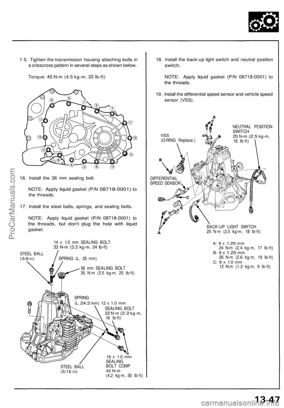
1 5 . Tighte n th e transmissio n housin g attachin g bolt s i n
a crisscros s patter n in severa l step s a s show n below .
Torque : 4 5 N- m (4. 5 kg-m , 3 3 Ib-ft )
16 . Instal l th e 3 6 m m sealin g bolt .
NOTE :
Apply liquid gaske t (P/ N 08718-0001 ) to
th e threads .
17 . Instal l th e stee l balls , springs , an d sealin g bolts .
NOTE : Appl y liqui d gaske t (P/ N 08718-0001 ) t o
th e threads , bu t don' t plu g th e hol e with liquid
gasket .
STEEL BAL L(3/8 in)
14 x 1. 0 m m SEALIN G BOL T33 N- m (3. 3 kg-m , 2 4 Ib-ft )
SPRIN G (L . 2 5 mm )
3 6 m m SEALIN G BOL T
3 5 N- m (3. 5 kg-m , 2 5 Ib-ft )
SPRIN G
(L. 24. 2 mm ) 12 x 1. 0 m m
SEALIN G BOL T22 N- m (2. 2 kg-m ,16 Ib-ft )
STEE L BAL L(5/16 in)
16 x 1. 0 m mSEALIN G
BOL T COM P
42 N- m(4.2 kg-m , 3 0 Ib-ft )
18. Instal l th e back-u p ligh t switc h an d neutra l positio n
switch.
NOTE: Appl y liqui d gaske t (P/ N 08718-0001 ) t o
the threads .
19. Instal l th e differentia l spee d senso r an d vehicl e spee d
senso r (VSS) .
VSS(O-RIN G Replace. ) NEUTRA
L POSITIO N
SWITCH25 N- m (2. 5 kg-m ,18 Ib-ft )
DIFFERENTIA L
SPEE D SENSO R
BACK-UP LIGH T SWITC H
2 5 N- m (2. 5 kg-m , 1 8 Ib-ft )
A: 8 x 1.2 5 mm24 N- m (2. 4 kg-m , 1 7 Ib-ft )B: 8 x 1.2 5 mm26 N- m (2. 6 kg-m , 1 9 Ib-ft )C: 6 x 1. 0 m m12 N- m (1. 2 kg-m , 9 Ib-ft )
ProCarManuals.com
Page 366 of 1640
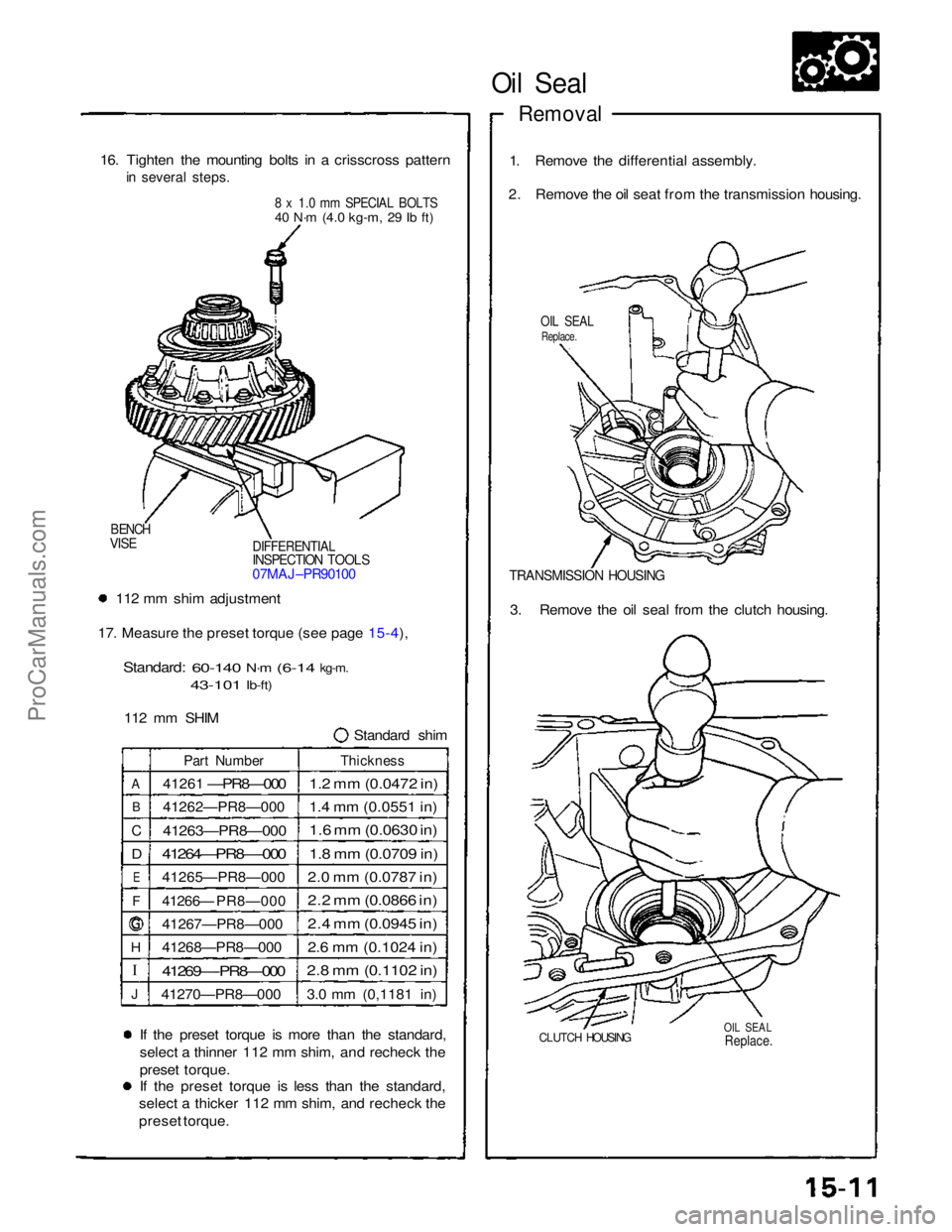
16. Tighte n th e mountin g bolt s i n a crisscros s patter n
i n severa l steps .
8 x 1. 0 m m SPECIA L BOLT S
4 0 N- m (4. 0 kg-m , 2 9 Ib-ft )
BENC H
VIS E
DIFFERENTIA LINSPECTION TOOL S07MAJ-PR9010 0
• 11 2 m m shi m adjustmen t
17 . Measur e th e prese t torqu e (se e pag e 15-4 ).
Standard :
60-140 N-m (6-1 4 kg-m ,
43-10 1 Ib-ft)
11 2 m m SHI M
Standar d shi m
If th e prese t torqu e i s mor e tha n th e standard ,
selec t a thinne r 11 2 m m shim , an d rechec k th e
prese t torque .
I f th e prese t torqu e i s les s tha n th e standard ,
selec t a thicke r 11 2 m m shim , an d rechec k th e
prese t torque .
ProCarManuals.com
Page 367 of 1640

I
Oil Seal
Removal
16. Tighten the mounting bolts in a crisscross pattern
in several steps.
8 x 1.0 mm SPECIAL BOLTS
40 N·m
(4.0 kg-m,
29 Ib ft)
1. Remove the differential assembly.
2. Remove the oil seat from the transmission housing.
OIL SEAL
Replace.
DIFFERENTIAL
INSPECTION TOOLS
07MAJ–PR90100
BENCH
VISE
TRANSMISSION HOUSING
112 mm shim adjustment
17. Measure the preset torque (see page 15-4),
Standard:
60-140
N·m
(6-14
kg-m.
43-101
Ib-ft)
112 mm SHIM Standard shim3. Remove the oil seal from the clutch housing.
A
B
C
D
E
F
H
J
Part Number
41261
—PR8—000
41262—PR8—000
41263—PR8—000
41264—PR8—-000
41265—PR8—000
41266— PR8—000
41267—PR8—000
41268—PR8—000
41269—-PR8—000
41270—PR8—000
Thickness
1.2 mm (0.0472 in)
1.4 mm (0.0551 in)
1.6 mm (0.0630 in)
1.8 mm (0.0709 in)
2.0 mm (0.0787 in)
2.2 mm (0.0866 in)
2.4 mm (0.0945 in)
2.6 mm (0.1024 in)
2.8 mm (0.1102 in)
3.0 mm (0,1181 in)
If the preset torque is more than the standard,
select a thinner 112 mm shim, and recheck the
preset torque.
If the preset torque is less than the standard,
select a thicker 112 mm shim, and recheck the
preset torque.
CLUTCH HOUSING
OIL SEAL
Replace.
ProCarManuals.com
Page 369 of 1640

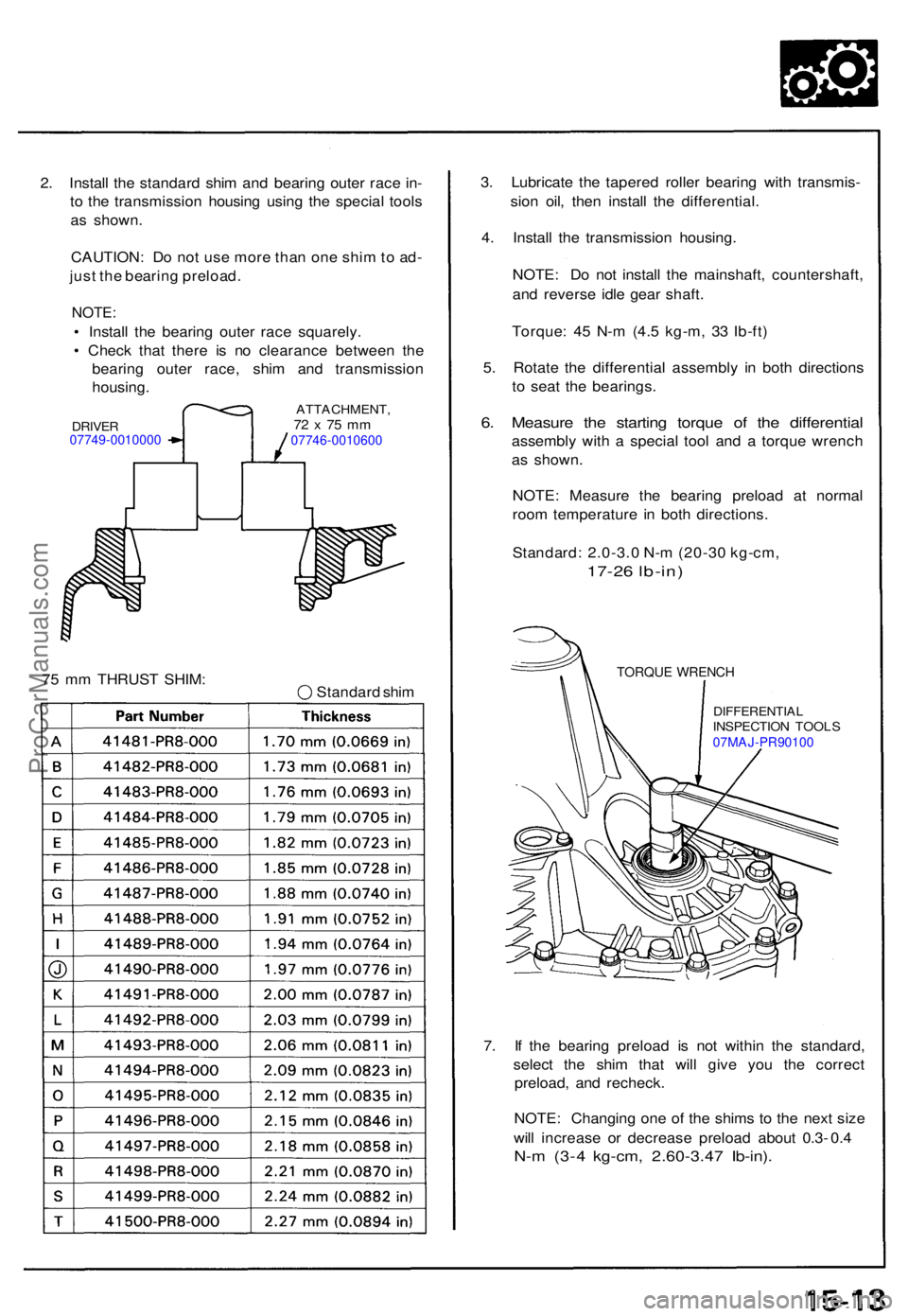
2. Instal l th e standar d shi m an d bearin g oute r rac e in -
t o th e transmissio n housin g usin g th e specia l tool s
a s shown .
CAUTION : D o no t us e mor e tha n on e shi m to ad -
jus t th e bearin g preload .
NOTE:
• Instal l th e bearin g oute r rac e squarely .
• Chec k tha t ther e i s n o clearanc e betwee n th e
bearin g oute r race , shi m an d transmissio n
housing .
7 5 m m THRUS T SHIM :
Standard shi m 3
. Lubricat e th e tapere d rolle r bearin g wit h transmis -
sio n oil , the n instal l th e differential .
4 . Instal l th e transmissio n housing .
NOTE : D o no t instal l th e mainshaft , countershaft ,
an d revers e idl e gea r shaft .
Torque : 4 5 N- m (4. 5 kg-m , 3 3 Ib-ft )
5 . Rotat e th e differentia l assembl y i n bot h direction s
t o sea t th e bearings .
6. Measur e th e startin g torqu e o f th e differentia l
assembly wit h a specia l too l an d a torqu e wrenc h
a s shown .
NOTE : Measur e th e bearin g preloa d a t norma l
roo m temperatur e i n bot h directions .
Standard : 2.0-3. 0 N- m (20-3 0 kg-cm ,
17-26 lb-in )
TORQUE WRENC H
DIFFERENTIA LINSPECTION TOOL S07MAJ-PR90100
7. I f th e bearin g preloa d i s no t withi n th e standard ,
selec t th e shi m tha t wil l giv e yo u th e correc t
preload , an d recheck .
NOTE : Changin g on e o f th e shim s t o th e nex t siz e
wil l increas e o r decreas e preloa d abou t 0. 3- 0. 4
N- m (3- 4 kg-cm , 2.60-3.4 7 Ib-in) .
DRIVE R07749-0010000
ATTACHMENT ,72 x 75 m m07746-0010600
ProCarManuals.com