1989 MITSUBISHI GALANT stop start
[x] Cancel search: stop startPage 157 of 1273
FUEL SYSTEM
Diagnosti
trouble
code No.
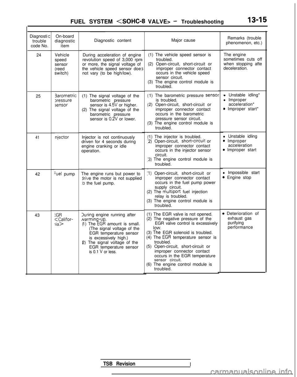
24
25
41
42Set pump
43
iGR;aC;lifor-
COn-board
diagnostic
item
Vehicle
speed
sensor
(reed
switch) 3arometric
Iressuresensor
njector
Diagnostic content
Major cause
During acceleration of engine
revolution speed of 3,000 rpm
or more, the signal voltage of
the vehicle speed sensor doe: not vary (to be high/low). (1) The vehicle speed sensor is
troubled.
(2) Open-circuit, short-circuit or
improper connector contact
occurs in the vehicle speed
sensor circuit.
(1) The signal voltage of the barometric pressure
sensor is 4.5V or higher.
(2) The signal voltage of the barometric pressure
sensor is
0.2V or lower.
Injector is not continuously
driven for 4 seconds during
engine cranking or idle
operation.
The engine runs but power to
irive the motor is not supplied
:o the fuel pump.
luring engine running after Narming-up,
1) The
EGR amount is small.
(The signal voltage of the EGR temperature sensor
is excessively high.)
2) The signal voltage of the
EGR temperature sensor
is 0.1 V or less.
(3) The engine control module is troubled.
1) The barometric pressure sense
is troubled.
2) Open-circuit, short-circuit or
improper connector contact
occurs in the barometric pressure sensor circuit.
‘3) The engine control module is
troubled.
‘1) The injector is troubled.
12) Open-circuit, short-crrcuit
or
improper connector contact
occurs in the injector sensor
circuit.
13) The engine control module is
troubled.
:I) Open-circuit, short-circuit or improper connector contact
occurs in the fuel pump power
supply circuit.
(2) The
multiport fuel injection
relay is troubled.
(3) The engine control module is
troubled.
(1) The EGR valve is not opened.
(2) The negative pressure of the EGR valve control is excessively
(3)
?h”e EGR solenoid is troubled.
(4) The EGR temperature sensor is
troubled.
(5) Open-circuit, short-circuit or
improper connector contact
occurs in the EGR temperature
sensor circuit.
(6) The engine control module is troubled.
r 1l Unstable idling*
l Improper acceleration*
0 Improper start*
l Unstable idling
0 Improper acceleration
0 Improper start
l Impossible start
3 Engine stop4
4
,
B Deterioration of exhaust gaspurifying
performance
Remarks (trouble
phenomenon, etc.)
The engine
sometimes cuts off
when stopping afte
deceleration.
TSB RevisionI
Page 161 of 1273
FUEL SYSTEM
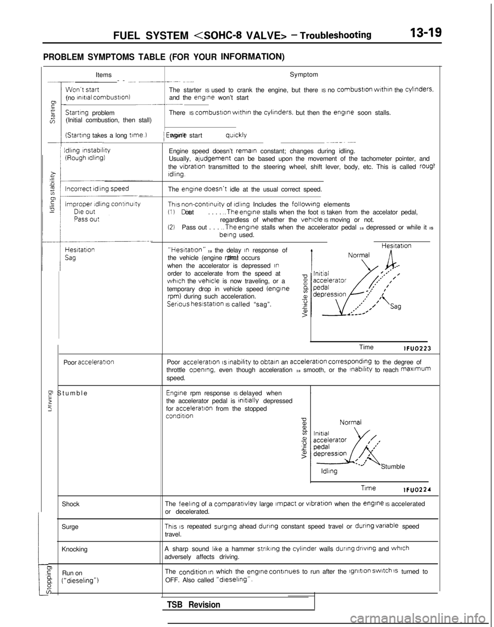
PROBLEM SYMPTOMS TABLE (FOR YOURINFORMATION)
:tShock
Surge
Knocking
0,GRun ona (“dieselrng”)
6
Items Symptom
-- -... __----. -~-
The starter IS used to crank the engine, but there IS no
combustron
wrthrn
the cylinders.
(no rnrtral combustron)
and the engine won’t start~-.-__Startrng
problem There IS combustron
wrthrn
the cylrnders.
but then the engrne
soon stalls.
(Initial combustion, then stall)
(Startrng takes a long t1me.l
I
Idling
rnstabrlrty
/ Engrne won’t start qurckly~--_~ -...
Engine speed doesn’t remain constant; changes during idling.
Usually, aludgement can be based upon the movement of the tachometer pointer, and
the
vibration transmitted to the steering wheel, shift lever, body, etc. This is call\
ed rougt
Idling.
The
engtnedoesn’t idle at the usual correct speed.
Thus non-contrnuity of rdlrng Includes the followrng elements(1) Die out
. . . . ..The
engine stalls when the foot IS taken from the accelator pedal,
regardless of whether the vehicle IS moving or not.(2)Pass out . . . ..The
engine stalls when the accelerator pedal IS depressed or while it IS berng
used.
“Hestatton” IS the delay In response of
the vehicle (engine rpm) that occurs
when the accelerator is depressed
Inorder to accelerate from the speed atwhich the vehicle is now traveling, or a
temporary drop in vehicle speed (enginerpm) during such acceleration. Hesltatron
Serious
hesstatlon IS called “sag”.
Poor
acceleration
E Stumbl
e
2
5
Time lFUO223
Poor
acceleration IS rnabilrty
to obtain an acceleration corresponding to the degree of
throttle opening, even though acceleration IS smooth, or the rnabrlrty to reach maxmum
speed.
Engrne rpm response IS delayed when .
the accelerator pedal is initrally
depressed
for acceleratron
from the stopped
condition ldllng
Stumble
Trme lFUO224
The
feeling of a comparatlvley large Impact or vrbration
when the engine IS accelerated
or decelerated.
This IS repeated surging
ahead dunng constant speed travel or dunng
vanable
speed
travel.
A sharp sound
IIke a hammer strtklng the cylinder walls during
dnvtng
and whrch
adversely affects driving.
The
condrtion In which the engrne
continues to run after the lgnltion switch 1s turned to
OFF. Also called
“dreselrng”.
TSB Revision
Page 174 of 1273
13-32
FUEL SYSTEM
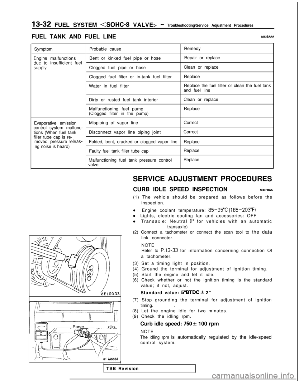
FUEL TANK AND FUEL LINEMlBEAAA
Symptom Probable cause Remedy
Engtne malfunctions
Bent or kinked fuel pipe or hose Repair or replace3ue to insufficient fuel
SUPPlYClogged fuel pipe or hoseClean or replace
Clogged fuel filter or in-tank fuel filter Replace
Water in fuel filter Replace the fuel filter or clean the fuel tank
and fuel line
Dirty or rusted fuel tank interior Malfunctioning fuel pump
(Clogged filter in the pump) Clean or replace
Replace
Evaporative emission Mispiping of vapor line
Correct
control system malfunc-
tions (When fuel tank Disconnect vapor line piping joint Correct
filler tube cap is re- moved, pressure releas-
Folded, bent, cracked or clogged vapor line Replace
ng noise is heard) Faulty fuel tank filler tube cap
Malfunctioning fuel tank pressure control
valve Replace
Replace
LL
m ~~ : Paper clip-
F l!;“I /yFp- -
izd--_7-01
A0086SERVICE ADJUSTMENT PROCEDURES
CURB IDLE SPEED INSPECTION
MlBFHAFt
(1) The vehicle should be prepared as follows before the inspection.
lEngine coolant temperature: 85-95°C (185-203°F)
l Lights, electric cooling fan and accessories: OFF
l Transaxle: Neutral
(P for vehicles with an automatic
transaxle)
(2) Connect a tachometer or connect the scan tool to the data
link connector.
NOTE
Refer to
P.13-33 for information concerning connection Of
a tachometer.
(3) Set a timing light in position.
(4) Ground the terminal for adjustment of ignition timing.
(5) Start the engine and let it idle.
(6) Check whether or not the ignition timing is the standard
value; if not, adjust.
Standard value:
5”BTDC + 2”
(7) Stop grounding the terminal for adjustment of ignition timing. .
(8) Let the engine idle for two minutes.
(9) Check the idling rpm.
Curb idle speed:
7502 100 rpm
NOTE
The idling rpm is automatically regulated by the idle-speed control system.
1
TSB Revision
Page 176 of 1273
13-34 FUEL SYSTEM
(5) Switch ON the ignition switch (but do not start the engine)and leave as if for 15 seconds or longer.
NOTE
When the ignition switch is switched ON, the idle speed
control plunger extends to the fast-idle opening degree,
and, after 15 seconds have passed, contracts to the initialposition and stops there.
Initial position: the suitable idling position at which the idle speed control motor position sensor output
voltage is
0.9V.
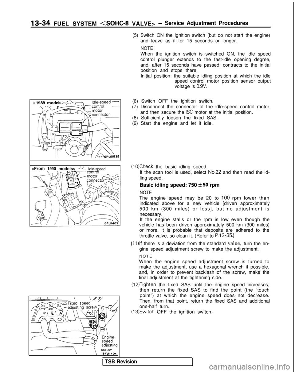
--\\screw 6FU1404(6) Switch OFF the ignition switch.
(7) Disconnect the connector of the idle-speed control motor, and then secure the
ISC motor at the initial position.
(8) Sufficiently loosen the fixed SAS.
(9) Start the engine and let it idle.
(10)Check the basic idling speed.
If the scan tool is used, select
No.22 and then read the id-
ling speed.
Basic idling speed: 750
+-50 rpm
NOTE
The engine speed may be 20 to 100 rpm lower than
indicated above for a new vehicle [driven approximately
500 km (300 miles) or less], but no adjustment is necessary.If the engine stalls or the rpm is low even though the
vehicle has been driven approximately 500 km (300 miles) or more, it is probable that deposits are adhered to the
throttle valve, so clean it. (Refer to
P.13-35.)
(1l)lf there is a deviation from the standard value, turn the en-
gine speed adjustment screw to make the adjustment.
NOT
E
When the engine speed adjustment screw is turned to make the adjustment, use a hexagonal wrench if possible,
and, in order to prevent backlash of the screw, make the
final adjustment at the tightening side.
(12)Tighten the fixed SAS until the engine speed increases;
then return the fixed SAS to find the point (the “touch
point”) at which the engine speed does not decrease.
Then, from that point, return the fixed SAS and additional
one-half turn. (13)Switch
OFF the ignition switch.
1 TSB Revision
Page 177 of 1273
FUEL SYSTEM
(14)Adjust the play of the accelerator cable. (Refer to P.13-
329.)
(15)Connect the idle-speed control motor’s connector.
(16)Adjust the throttle-position sensor.
(17)Start the engine again and let it run at idle speed for about
ten minutes; check to be sure that the idling condition is
normal.
THROTTLE BODY (THROTTLE VALVE AREA)
CLEANING
MllFlCK
(1)Start the engine and warm it up until the temperature of the
engine coolant reaches
80°C (176°F) or higher; then stop
the engine.
(2) Disconnect the air intake hose at the throttle body side.
(3) Spray cleaning liquid (from the intake port of the throttle body) onto the valve, and then leave as is for about fiveminutes.
(4) Start the engine and race it a few times; then let it run at idle speed for about one minute.
NOTE
If the engine idling speed is unstable (or the engine stalls),
let the engine run with the throttle valve slightly open.
(5) If deposits are not removed from the throttle valve, repeat steps (3) and (4).
(6) Connect the air intake hose.
(7) Using the scan tool, erase the diagnostic trouble code, or disconnect the battery’s ground cable for ten seconds orlonger and then reconnect it.
(8) Adjust the basic idle speed (engine speed adjusting screw). (Refer to
P.13-33.)
(9) Adjust the throttle position sensor.
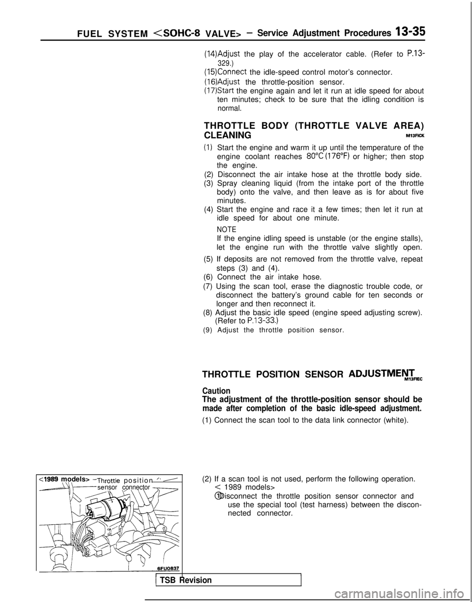
(2) If a scan tool is not used, perform the following operation.
< 1989 models> @ Disconnect the throttle position sensor connector and
use the special tool (test harness) between the discon-
nected connector.
r1 TSB Revision
THROTTLE POSITION SENSOR ADJUSTMEiW&
Caution
The adjustment of the throttle-position sensor should be
made after completion of the basic idle-speed adjustment.
(1) Connect the scan tool to the data link connector (white).
,
Page 178 of 1273
13-36 FUEL SYSTEM
:I989 models>
M
D9684783FUO179
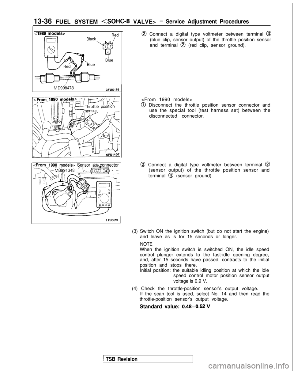
@ Connect a digital type voltmeter between terminal @
(blue clip, sensor output) of the throttle position sensor
and terminal
@I (red clip, sensor ground).
@I Disconnect the throttle position sensor connector and use the special tool (test harness set) between the
disconnected connector.
@ Connect a digital type voltmeter between terminal @
(sensor output) of the throttle position sensor and
terminal
@I (sensor ground).
1 FU0619
(3) Switch ON the ignition switch (but do not start the engine) and leave as is for 15 seconds or longer.
NOTE
When the ignition switch is switched ON, the idle speedcontrol plunger extends to the fast-idle opening degree,
and, after 15 seconds have passed, contracts to the initial
position and stops there.Initial position: the suitable idling position at which the idle speed control motor position sensor output
voltage is 0.9 V.
(4) Check the throttle-position sensor’s output voltage. If the scan tool is used, select No. 14 and then read the
throttle-position sensor’s output voltage.
Standard value: 0.48-0.52
V
1 TSB Revision
Page 219 of 1273
FUEL SYSTEM
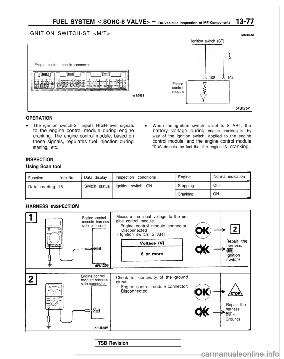
IGNITION SWITCH-ST
>
Engine control module connector
II
Enginecontrolmodule01 LO838
Ignition switch (ST)
7
Tr108104
T-7JL
6FU1257
OPERATION
lThe ignition switch-ST inputs HIGH-level signalslWhen the ignition switch is set to START, the
to the engine control module during engine battery voltage during engine cranking is, by
cranking. The engine control module, based onway of the ignition switch, applied to the engine
those signals, regulates fuel injection during
control module, and the engine control module
starting, etc.thus detects the fact that the engine is cranking.
INSPECTION
Using Scan tool
Function Item No.1 Data display
Inspection conditions EngineNormal indication
Data reading 18 Switch status
Ignition switch: ON
Stopping
OFF
CrankingON
HARNESS INSPECTlON
Engine controlmodule harness
side connector
Measure the input voltage to the en-
gine control module.
. Engine control module connector: Disconnected
- Ignition switch: START
r6FU1259i
Repair theharness. @El-
Ground)
TSB Revision
Page 221 of 1273
FUEL SYSTEM
INSPECTION
Using Scan tool
Ignition switch-ST
Function Item No.Data display Check conditions
EngineNormal display
Data reading 18 Switch status
. Ignition switch: ON Stopped
OFF
CrankingON
Park/neutral position switch
Function
Item No.Data display
Check conditions Selector lever position
Normal display
Data reading 29 Shift position
. Ignition
swatch: ON Por NPor N
D, 2, Lor RD, 2, L or R
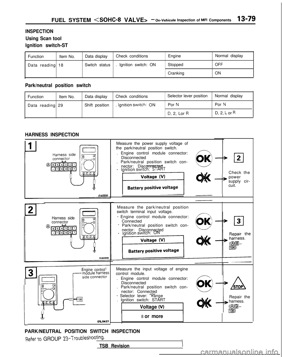
HARNESS INSPECTION
Harness sideconnector
Engine control
Measure the input voltage of engine
control module.
. Engine control module connector: Disconnected
. Park/neutral position switch con-
nector: Connected
* Selector lever: “P” range
. Ignition switch: START
Voltage (V)
:
1
Y-OlLO42’f
PARK/NEUTRAL POSITION SWITCH INSPECTION
Measure the power supply voltage of
the park/neutral position switch.
. Engine control module connector: Disconnected
. Park/neutral position switch con-
nector: Disconnected
Check the
I+
power
supply cir-
cuit.
Measure the park/neutral position
switch terminal input voltage.
* Engine control module connector: ConnectedPark/neutral position switch con-
nector: Disconnected
8 or more
ASTOP
Repair the
harness.
C@W lIEI)
Refer to GROUP 23-Troubleshooting.
TSB RevisionI