1989 MITSUBISHI GALANT ad blue
[x] Cancel search: ad bluePage 145 of 1273
FUEL SYSTEM
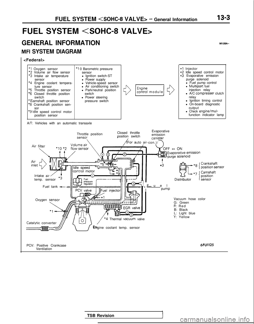
FUEL SYSTEM
GENERAL INFORMATION
MFI SYSTEM DIAGRAM
*1 Oxygen sensor
*2
Volume air flow sensor *3
Intake air temperature
sensor *4
Engine coolant tempera-
ture sensor *5
Throttle position sensor *6
Closed throttle position
switch *7 Camshaft position sensor
*8
Crankshaft position sen-
sor
‘9 Idle
speed control motor
position sensor
*I 0 Barometric pressure sensor
l Ignition switch-ST
l Power supply
l Vehicle-speed sensor
l Air conditioning switch
l Park/neutral position
switch
l Power steering pressure switch
A/T: Vehicles with an automatic transaxle
()/ $%?i modul
e
Closed throttle Evaporative
position switch emission canister
ir-con.)/ \
10
Throttle position
temp. sensor Fuel tank
- =
Oxygen M13BA-
I
*I Injector~2 Idle speed control motort3 Evaporative emission
purge solenoid
l Fuel pump control
l Multiport fuelinjection relay
l A/C compresser clutch
relay
l Ignition timing control
l On-board diagnostic
output
l Check engine/mul-function indicator lamp
Fue
l
: -
I
pump
purge
solenolo Catalvtic
converter
\/ *4 Thermal vacu
G: Green
R: Re
d
B: Black
L: Light blue
Y: Yellow
dJJ/ U’Engine coolant temp. sensor
PCV: Positive Crankcase Ventilation
6FU1125
TSB Revision
Page 146 of 1273
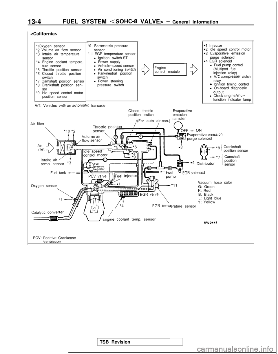
13-4FUEL SYSTEM
*2 Volume
air
flow sensor$3 Intake air temperature
sensor
*4 Engine coolant tempera-ture sensor
“5 Throttle position sensor‘6 Closed throttle position switch
*7 Camshaft position sensor*8 Crankshaft position sen-
sor
*9 Idle speed control motor position sensor “I 0
Barometric pressure
sensor
‘11 EGR temperature sensor
l Ignition switch-STl Power supply
l
Vehrcle-speed sensor
l Air conditioning switch
l Park/neutral position
switch
l Power steering pressure switchI13
Engrnecontrol module10
rl Injectort2 Idle speed control motorr3 Evaporative emission
purge solenoid
r4 EGR solenoidl Fuel pump control
(Multiport fuel
injection relay)
l A/C compresser clutchrelay0 Ignition timing control
l On-board diagnostic
output
l Check engine/muj-function indicator lamp
A/T: Vehicles
with an automatrc
transaxle
Closed throttleposition switch Evaporative
emission
/(For auto air-con.) can’ster
/ n
Vacuum hose
G: Green
R: Red
B: Black L: Light blue
Y: Yellow
erature sensor Air
filter
Fuel tank - =
Oxygen sensor
\ U /Eni coolant temp. sensor1FUO447
Crankshaft
position sensor
Camshaft
position
sensor
color
PCV: Posrtive
Crankcase
TSB Revision
Page 178 of 1273
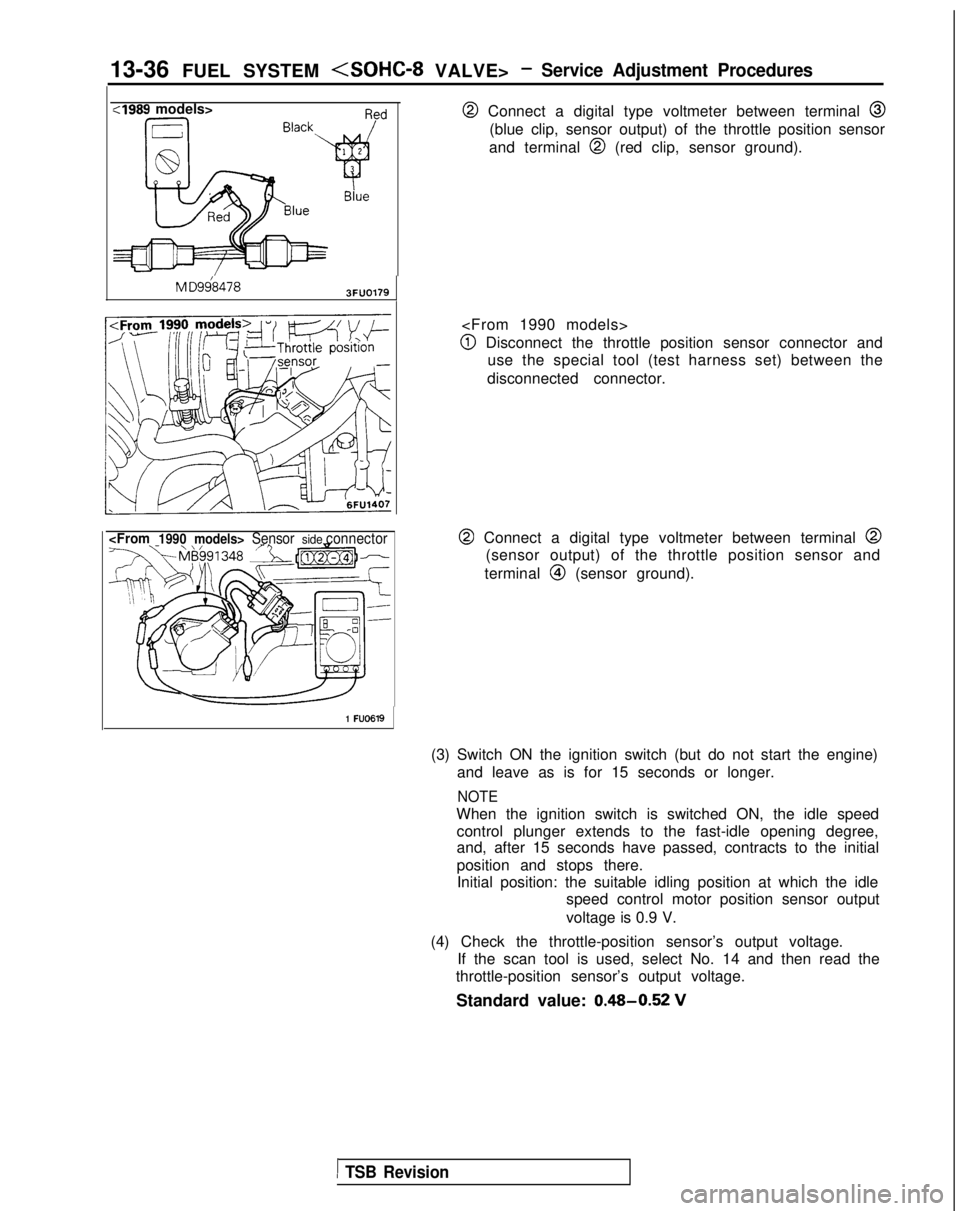
13-36 FUEL SYSTEM
:I989 models>
M
D9684783FUO179
@ Connect a digital type voltmeter between terminal @
(blue clip, sensor output) of the throttle position sensor
and terminal
@I (red clip, sensor ground).
@I Disconnect the throttle position sensor connector and use the special tool (test harness set) between the
disconnected connector.
@ Connect a digital type voltmeter between terminal @
(sensor output) of the throttle position sensor and
terminal
@I (sensor ground).
1 FU0619
(3) Switch ON the ignition switch (but do not start the engine) and leave as is for 15 seconds or longer.
NOTE
When the ignition switch is switched ON, the idle speedcontrol plunger extends to the fast-idle opening degree,
and, after 15 seconds have passed, contracts to the initial
position and stops there.Initial position: the suitable idling position at which the idle speed control motor position sensor output
voltage is 0.9 V.
(4) Check the throttle-position sensor’s output voltage. If the scan tool is used, select No. 14 and then read the
throttle-position sensor’s output voltage.
Standard value: 0.48-0.52
V
1 TSB Revision
Page 201 of 1273
FUEL SYSTEM
Re
Blu
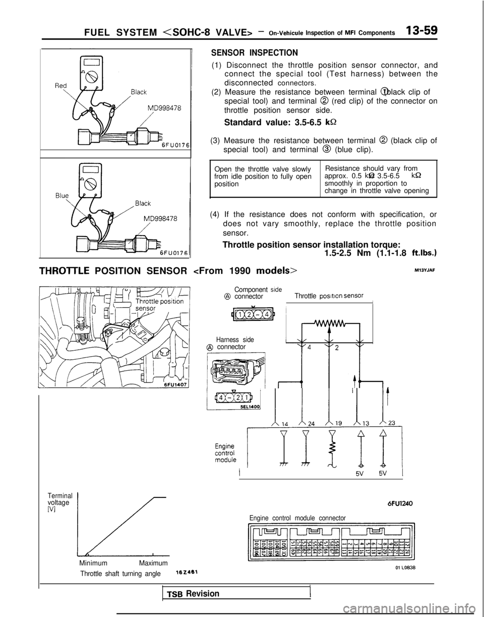
THROlTLE POSITION SENSOR
SENSOR INSPECTION
(1) Disconnect the throttle position sensor connector, and
connect the special tool (Test harness) between the
disconnected connectors.
(2) Measure the resistance between terminal @ (black clip of
special tool) and terminal @
(red clip) of the connector on
throttle position sensor side.
Standard value: 3.5-6.5
kS2
(3) Measure the resistance between terminal @ (black clip of
special tool) and terminal @
(blue clip).
Open the throttle valve slowly Resistance should vary from
from idle position to fully open approx. 0.5 kQ to 3.5-6.5
kQ
position
smoothly in proportion to
change in throttle valve opening
(4) If the resistance does not conform with specification, or does not vary smoothly, replace the throttle position
sensor.
Throttle position sensor installation torque: 1.5-2.5 Nm (1.1-1.8
ft.lbs.1
Component srde@ connectorThrottle posltlon SensorI
Harness side@ connector
m 1,. I,, .I,, I,, It,
~$-T~ ;I
TerminalvoltageIV1
Engine control module connector
Minimum
Maximum01 LO.0838Throttle shaft turning angle102461
TSB Revision
Page 276 of 1273
13-134FUEL SYSTEM (SOHC-16 VALVE> -Service Adjustment Procedures
BASIC IDLE SPEED ADJUSTMENTMlIFHBX
NOTE
1. The standard idling speed has been adjusted, by the en-
gine speed adjusting screw, by the manufacturer, and
there should usually be no need for readjustment.
2. Use the following procedure to adjust when the idling speed drops due to an incorrect adjustment, high idling
speed, or when a load such as the air conditioning is ap-
plied on the engine.
3. The adjustment, if made, should be made after first con- firming that the spark plugs, the injectors, the idle air con-
trol motor, the compression pressure, etc. are all normal.
(I ) The vehicle should be prepared as follows before the inspec- tion and adjustment.
l Engine coolant temperature:
85-95°C (185-203°F)
l Lights, cooling fan and accessories: OFF
l Transaxle: neutral (A/T for
P range)
l Steering wheel: neutral position
(2) Connect the scan tool to the data link connector (white).
NOTE
When the scan tool is connected, the diagnostic test mode control terminal should be grounded.
(3) If the scan tool is not used, follow the steps below.
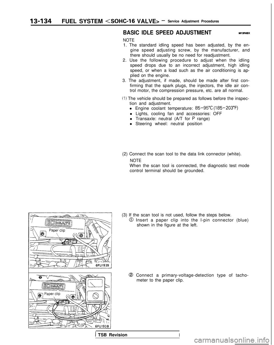
@I Insert a paper clip into the l-pin connector (blue) shown in the figure at the left.
0 Connect a primary-voltage-detection type of tacho-meter to the paper clip.
1 TSB RevisionI
Page 338 of 1273
13-196FUEL SYSTEM
FUEL SYSTEM
GENERAL INFORMATION
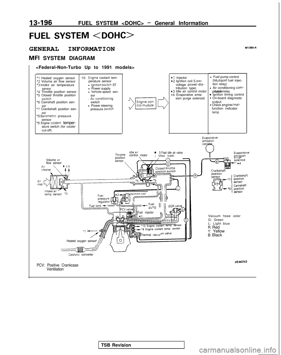
MFI SYSTEM DIAGRAMMl
3BA-A
*1 Injector*2 Ignition coil
(Low-
voltage power-drs-
tribution type)
*3 Idle air control motork4 Evaporative emis-
sion purge solenoid l Fuel pump control (Multiport
fuel injec-
tion relay)
l Air conditioning
corm- pressor clutch relay
* Ignition timing control) On-board diagnostic
output
) Check engine/mal-
function indicator
lamp
Engine coolant tem-
perature sensor
l Ignition swatch STl Power supplyl Vehicle-speed sen-sor
. Arr conditioning
switch
l Power steering
pressure
swatch
‘I Heated oxygen sensor ‘10*2
Volume air flow sensor *3
Intake air temperaturesensor‘4 Throttle position sensor *5
Closed throttle position
swrtch *6
Camshaft position sen-
sor “7
Crankshaft position sen-
sor“8 Barometrrc pressure
sensor
‘9 Engine coolant temper-ature switch (for cooler
cut-off)
Evaporatrveemrssion canister
Evaporatrveemlsslo”Idle airThronlecontrol motorl 3 Fast idle air valveI (Wax tvoe)position\Volume air/sensor3flow sensorf \//n,r\l 2 '8
- lnnhnn toll III1 II
II-“,--?% 11 11 EGR,/alveI.l”lll)i
Fuel injectorII
II
Vacuum hose color
G: Green
L: Light blue
I?: RedY: Yellow5: Black
Heated oxygen sensor Thermal
vacuu
a uCatalytrc converter
HMO163PCV: Positive CrankcaseVentilation
TSB Revision
Page 339 of 1273
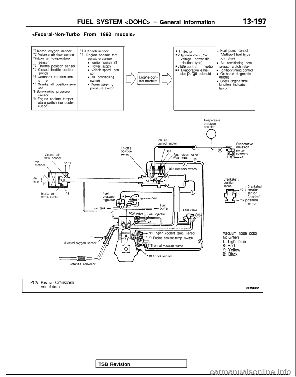
‘1 Heated oxygen sensor‘2 Volume air flow sensor
“3 intake air temperature
sensor‘4 Throttle position sensor‘5 Closed throttle position
switch
‘6 Camshaft Dosltion sen-
so
r
*7 Crankshaft position sen-sor‘8
Barometnc
pressure
sensor
‘9 Engine coolant temper-
ature switch (for cooler
cut-off)
‘I 0 Knock sensor ‘11
Engien coolant tem-
perature sensor
l Ignition switch STl Power supplyl Vehicle-speed sen-
sor
l Air conditioningswitchl Power steeringpressure switch
Volume airflow sensor \
Idle air
FUEL SYSTEM
* 1 Injector*2 Ignition coil (Low-
voltage power-dis-
tribution type)
*3 Idle air control motel*4 Evaporative emis-sion purge solenoid
l Fuel pump control (Multiport
fuel injec-
tion relay)
l Air conditioning com-pressor clutch relay
l Ignition timing control
l On-board diagnosticoutputl Check engine/mal-
function indicator
lamp
Evaporativeemissioncanister
Q
ThrottlepOSltlOnSt?“SW
\
control motor
r
Fast Idle air valveWax tape)
TSB Revision
e , lylllll”rl
COll
Fuel- wmpEGR valve
'1 A
Heated oxygen sensor /$$y/.\‘“I
w ‘11 Englen coolant temp. sensorF ‘9 Engine coolant temp. switch
Thermal vacuum valve
Crankshaft
position
sensor
‘7 positlon ICrankshaft
sensor
I
Camshaft‘6 positionsensor
Vacuum hose color G: Green
L: Light blueR: RedY: YellowB: Black
Catalytic convener
PCV: Posmve CrankcaseVentllatlon6EMO362
Page 340 of 1273
13-198FUEL SYSTEM
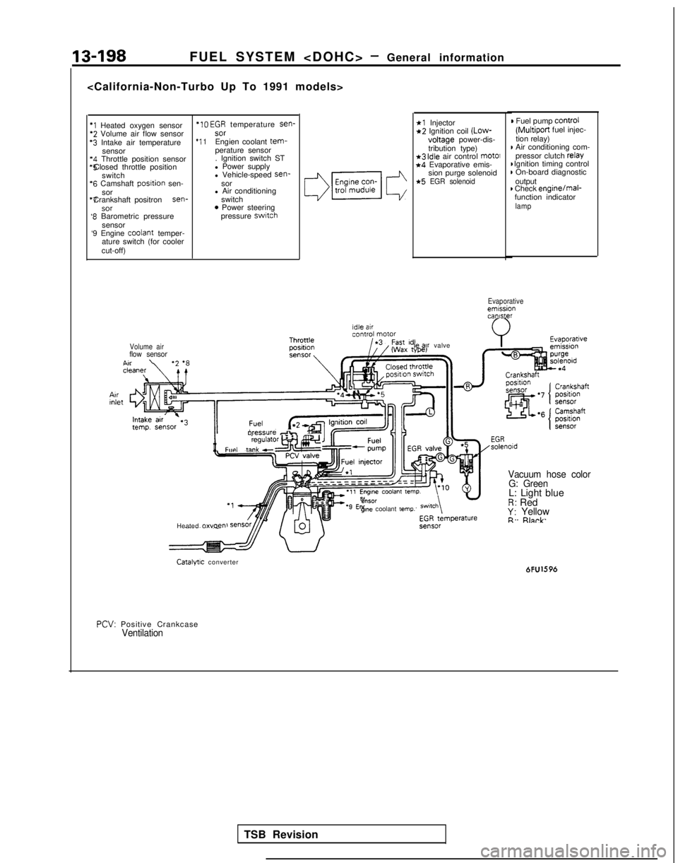
*I Heated oxygen sensor *IO
EGR temperature sen-*2 Volume air flow sensor
sor‘3 Intake air temperature
*I 1Engien coolant tem-sensor
perature sensor‘4 Throttle position sensor . Ignition switch ST*5 Closed throttle position
l Power supply
switch l Vehicle-speed sen-
‘6 Camshaft
posltion
sen- sor
sor l Air conditioning“7 Crankshaft positron sen-
switch
SOT0 Power steering‘8 Barometric pressure pressure switch
sensor
‘9 Engine coolant
temper-
ature switch (for cooler
cut-off)
*l Injector*2 Ignition coil (Low-
voltage
power-dis-
tribution type)
*3 idle air control mot01*4 Evaporative emis- sion purge solenoid
*5 EGR solenoid
) Fuel pump control
(Multiport
fuel injec-
tion relay)
I Air conditioning com- pressor clutch relay I Ignition timing control
) On-board diagnostic
output
) Check enginejmal-
function indicator
lamp
Evaporativeemissioncanister
Volume air
flow sensorA..\
II
oressure db,Fun, taw”l”‘“‘~
Heated 0~““~” le
ax valve
e”SOrgme coolant temp.
Vacuum hose color
G: Green
L: Light blueR: RedY: YellowR. Rlnrk
Catalytic converter 6FU1596
PCV:
Positive Crankcase
Ventilation
TSB Revision