1989 MITSUBISHI GALANT steering
[x] Cancel search: steeringPage 3 of 1273
00-l
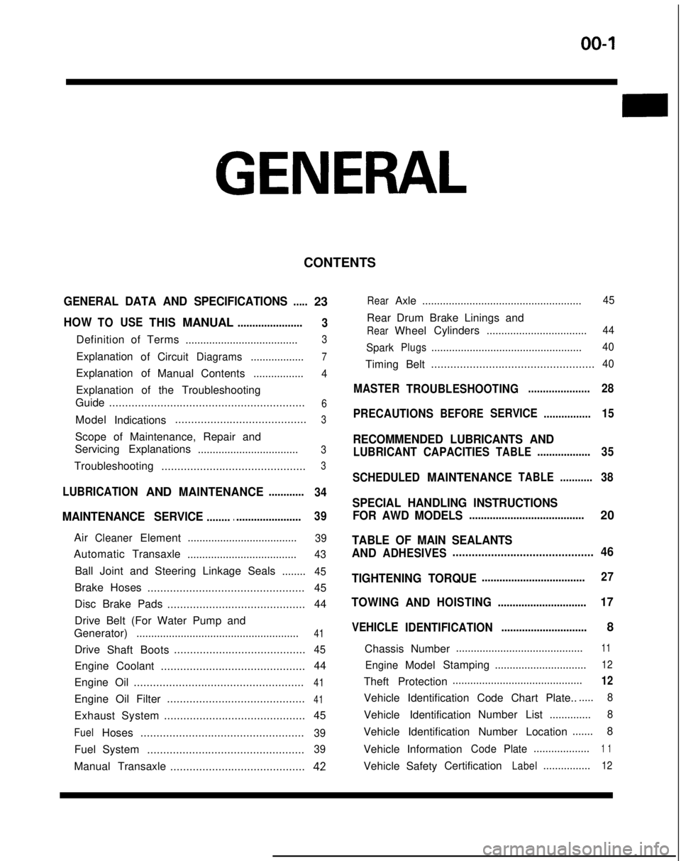
GENERAL
CONTENTS
GENERAL DATA AND SPECIFICATIONS.....23
HOWTOUSETHISMANUAL......................
3
Definition of Terms ......................................3
ExplanationofCircuitDiagrams..................7
Explanation of
ManualContents .................4
Explanation of the Troubleshooting
Guide .............................................................
6
Model
Indications .........................................3
Scope of Maintenance, Repair and
Servicing Explanations
..................................
3
Troubleshooting .............................................3
LUBRICATIONANDMAINTENANCE............
34
MAINTENANCE SERVICE............................... 39
AirCleanerElement
.....................................39
Automatic
Transaxle
.....................................43
Ball Joint and Steering Linkage Seals ........45
Brake Hoses................................................. 45
Disc Brake Pads ........................................... 44
Drive Belt (For Water Pump and
Generator) .......................................................
41
Drive
Shaft Boots .........................................45
Engine Coolant
............................................. 44
Engine Oil .....................................................
41
Engine Oil Filter ...........................................41
Exhaust System
............................................ 45
FuelHoses
...................................................39
Fuel System
.................................................39
Manual Transaxle ..........................................42
RearAxle......................................................45
Rear Drum Brake Linings and
RearWheel Cylinders
..................................44
Spark
Plugs...................................................40
Timing Belt...................................................40
MASTER
TROUBLESHOOTING.....................28
PRECAUTIONS
BEFORESERVICE................15
RECOMMENDED LUBRICANTS AND
LUBRICANT CAPACITIESTABLE..................35
SCHEDULED
MAINTENANCETABLE ...........38
SPECIAL HANDLING INSTRUCTIONS
FOR AWD MODELS
.......................................20
TABLE OF MAIN SEALANTS
AND
ADHESIVES ............................................46
TIGHTENING TORQUE
................................... 27
TOWING
ANDHOISTING ..............................17
VEHICLE
IDENTIFICATION .............................8
Chassis Number ...........................................
11
EngineModel
Stamping
...............................12
Theft Protection ............................................12
Vehicle Identification Code Chart Plate.......
8
Vehicle Identification Number List
..............8
Vehicle Identification Number Location .......
8
Vehicle Information
CodePlate...................1 1
Vehicle SafetyCertificationLabel................12
Page 7 of 1273
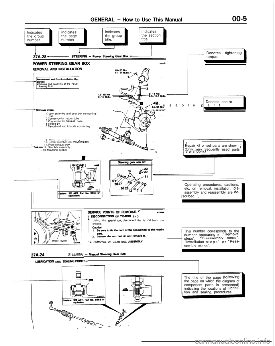
GENERAL - How to Use This Manual
QfitIIICQ CTEEQINC CFAR RnY..^-TV..&” Y.LLI.II.Y Y_.. w-1.
REMOVAL AND INSTALLATION
1, Jpn assemble and gear box connecting
2 Connectlo” for return tube
3 Connectm
for pressure hose4 cotter P!”6 T!e-rod end and knuckle connecting
I
J rl”.#l ~“,. dLlrr_. ..__
10. Center member rear mouniing
bou11, Front exhaust p’pe4. H 12. Gear box assembly
. . 13. Mounting rubber Denotes non-re-
p usable part
.
Y.T-*c As..
-
6
Repair kit or set parts are shown.
(Only very frequently used parts
Operating procedures, cautions,
II-’ iY,W11 ’etc. on removal, installation, dis-
se&an: 3rM&rr&paNo.~3W[scribed, ,~ 1assembly and reassembly are
de-
37A-24STEERING- NINA Steering Gear Box
-SERVICE POINTS OF
REMOVALJll37?kM6. DlSCONNECllON OF TIEROD END
Using the special tool, disconnect
the tie rod from theknuckle.ceurion1. BesretotiethewrdofthespeciaitodtomenP-.2. Loosenthenutbutdonotremoveit.
12. REMOVAL OF GEAR BOX ASSEMBLY
Thus number corresponds to the
number ?pyi:,“~&‘R~;;?Isteps”,“Installation steps” or “Reas-semblv steps”.
/LUBRlCATlON AND SEALING POINTS-
The title of the page (fOilOWingthe page on which the diagram of
component parts is presented)
indicating the locations of lubnca-
tion and sealingprocedures.
Page 18 of 1273
00-l 6GENERAL - Precautions before Service
Caution
1. Before connecting or disconnecting the negative
cable, be sure to turn off the ignition switch and the
lighting switch.
(If this is not done,there is the possibility of
semiconductor parts being damaged.)
2.For MFI-equipped models, after completion of the
work steps [when the battery’s negative (-) termi-
nal is connected], warm up the engine and allow it
to idle for approximately five minutes under the
conditions described below, in order to stabilize
engine control conditions, and then check to be
sure that the idling is satisfactory.
Engine coolant temperature:
85-95X (185-203°F)
Lights, electric fans, accessories: OFF
Transaxle: neutral position (A/T models: “N” or
“P”)
Steering wheel:neutral (center) position
mm (tn.1
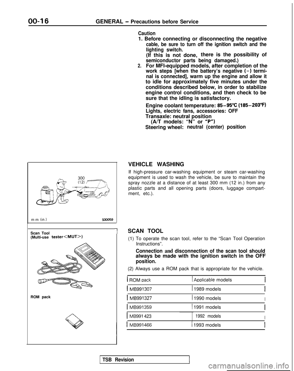
Scan Tool(Multi-use tester
ROM pack
1
VEHICLE WASHING
If high-pressure car-washing equipment or steam car-washing
equipment is used to wash the vehicle, be sure to maintain the
spray nozzle at a distance of at least 300 mm (12 in.) from any plastic parts and all opening parts (doors, luggage compart-
ment, etc.).
SCAN TOOL (1) To operate the scan tool, refer to the “Scan Tool Operation Instructions”.
Connection and disconnection of the scan tool should
always be made with the ignition switch in the OFF
position.
(2) Always use a ROM pack that is appropriate for the vehicle.
1 ROM oack1 Aoblicable models
1 MB9913071 1989 modelsI
1 MB9913271 1990 modelsI
1 MB991359( 1991 models
IMB991 4231992 modelsI
1 MB9914661 1993 models
TSB Revision
Page 19 of 1273
GENERAL - Towina and Hoisting
00-l 7
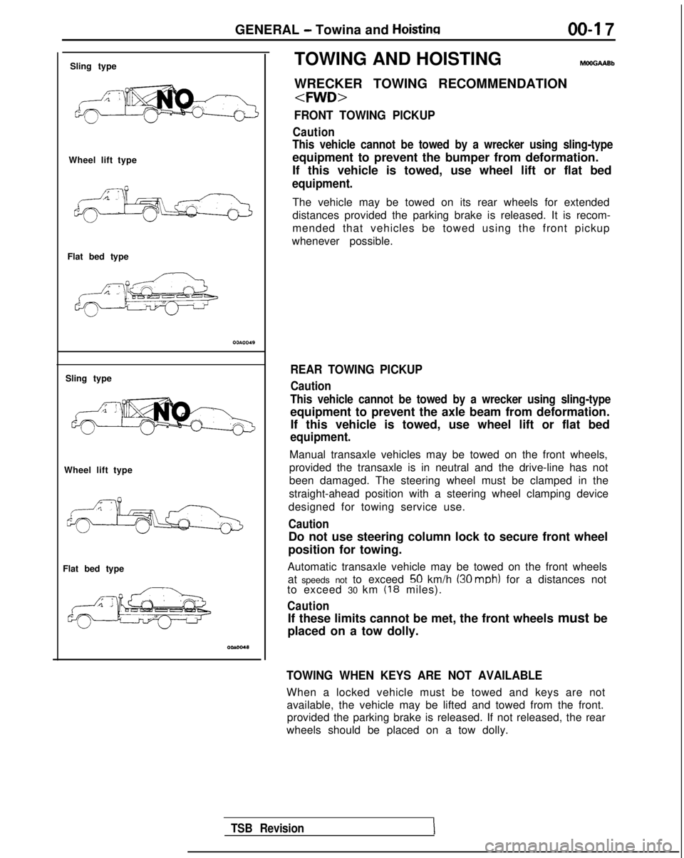
Sling type
Wheel lift type
Flat bed type
Sling type
Wheel lift type
Flat bed type TOWING AND HOISTING
WRECKER TOWING RECOMMENDATION
FRONT TOWING PICKUP
Caution
This vehicle cannot be towed by a wrecker using sling-type
equipment to prevent the bumper from deformation.
If this vehicle is towed, use wheel lift or flat bed
equipment.
The vehicle may be towed on its rear wheels for extended
distances provided the parking brake is released. It is recom-
mended that vehicles be towed using the front pickup
whenever possible.
REAR TOWING PICKUP
Caution
This vehicle cannot be towed by a wrecker using sling-type
equipment to prevent the axle beam from deformation. If this vehicle is towed, use wheel lift or flat bed
equipment.
Manual transaxle vehicles may be towed on the front wheels,
provided the transaxle is in neutral and the drive-line has not
been damaged. The steering wheel must be clamped in the
straight-ahead position with a steering wheel clamping device
designed for towing service use.
Caution
Do not use steering column lock to secure front wheel
position for towing.
Automatic transaxle vehicle may be towed on the front wheels at speeds not to exceed
50 km/h (30 mob) for a distances not
to exceed 30 km (18 miles).
Caution
If these limits cannot be met, the front wheels must be
placed on a tow dolly.
TOWING WHEN KEYS ARE NOT AVAILABLE
When a locked vehicle must be towed and keys are not available, the vehicle may be lifted and towed from the front.provided the parking brake is released. If not released, the rear
wheels should be placed on a tow dolly.
TSB Revision
Page 26 of 1273
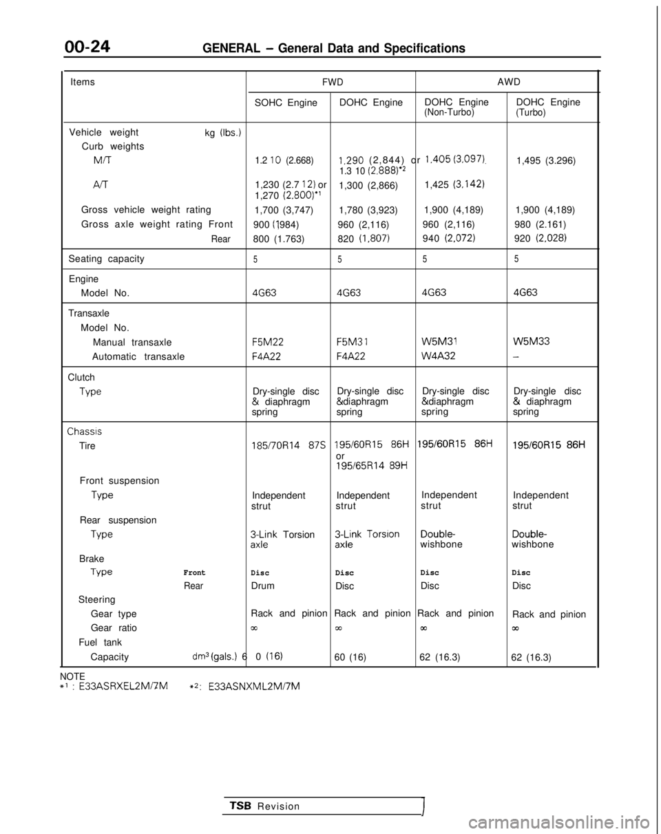
00-24GENERAL - General Data and Specifications
ItemsFWDAWD
SOHC Engine DOHC Engine DOHC Engine DOHC Engine
(Non-Turbo)
(Turbo)
Vehicle weight
kg (Ibs.)
Curb weightsMIT
1.2 10 (2.668)1.290 (2,844) or 1.405 (3.097).1,495 (3.296)1.3 10 (2.8881e2
/-v-r1,230 (2.7 12) or
1,300 (2,866) 1,425 (3.142)
1,270
(2.800)”
Gross vehicle weight rating 1,700 (3,747) 1,780 (3,923)1,900 (4,189)
1,900 (4,189)
Gross axle weight rating Front 900 (I ,984)
960 (2,116) 960 (2,116)
980 (2.161)
Rear800 (1.763)820 (1,807)940 (2.072)920 (2.028)
Seating capacity5 55 5
Engine
Model No.
4G634G63 4G634G63
Transaxle
Model No.Manual transaxle F5M22 F5M3
1 W5M31 W5M33
Automatic transaxle
F4A22F4A22 W4A32-
Clutch
Type
Dry-single disc
Dry-single disc
Dry-single disc Dry-single disc &
diaphragm & diaphragm & diaphragm &
diaphragm
spring spring spring
springChassis
Tire
185/7OR14 87s 195/60R15 86i-i 195/60R15 86ti195/60R15 86H
or
195/65R14 89H
Front suspension Type
Independent Independent
Independent
Independent
strut strut strut
strut
Rear suspension Type
3L$k Torsion3$k Torsion Double-
Double-
wishbone wishbone
Brake Type
Front
DiscDisc Disc
Disc
RearDrum
Disc Disc
Disc
Steering
Gear type Rack and pinion Rack and pinion Rack and pinion
Rack and pinion
Gear ratio
cc00m03
Fuel tank
Capacity
dm3(gals.) 60 (16)60 (16) 62 (16.3)
62 (16.3)
NOTE+’ : E33ASRXEL2Mi7M~2:
E33ASNXML2Mi7M
TSB RevisionI
Page 28 of 1273
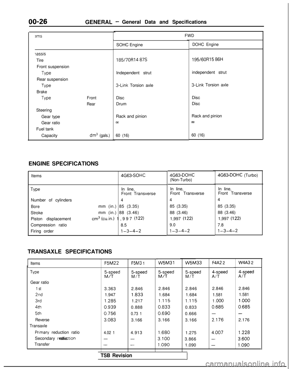
00-263ms
GENERAL -General Data and Specifications
FWD
iassis
Tire
Front suspension Type
Rear suspension Type
Brake
Type
Steering Gear type
Gear ratio
Fuel tank
Capacity
Front
Rear
dm3 (gals.)
L
SOHC EngineDOHC Engine
185/7ORl4 87s 195/60R15
86H
Independent strut independent strut 3-Link
Torsion axle 3-Link
Torsion axle
Disc
Drum Disc
Disc
Rack and pinion
cc
60 (16)
Rack and pinion
/cu
60 (16)
ENGINE SPECIFICATIONS Items Type
Number of cylinders
Bore
StrokePiston displacement
Compression ratio
Firing order 4G63-SOHC
In line,
Front Transverse
4
mm (in.) 85 (3.35)
mm (in.) 88 (3.46)
cm3 (win.) 1,997 (122)
8.5
1-3-4-2
TRANSAXLE SPECIFICATIONS
Items
Type
Gear ratio
1 st
2nd
3rd 4th
5th
Reverse
Transaxle
Pnmary reduction ratio
Secondary reductron ratio
Transfer F5M22
F5M3
1 5-speed
M/T W5M31
EFd
5-speed
M/T
F4A2 2 4-speed
A/T 4-speed
A/T
3.363 2.846 2.846 2.846
1.947 1.833
1.684 1.684 1.285
1.217
1.115 1.115
0.9390.8880.8330.833
0.7560.73 10.6900.666
3.0833.166
3.166
3.166 2.846 2.846
1.581
1.581
1 .ooo 1.000
0.6850.685
--
2.1762.176
4.02 14.9131.6801.2754.007
1.228
---3.1003.8663.600
---1.0901.090
1.0904G63-DOHC
(Non-Turbo) 4G63-DOHC
(Turbo)
In line, In line,
Front Transverse Front Transverse
44
85 (3.35) 85 (3.35)
88 (3.46) 88 (3.46)
1,997 (I
22)1,997 (I 22)
9.0
7.8
1-3-4-21-3-4-2
W5M33W4A3 2
TSB Revision1
Page 32 of 1273
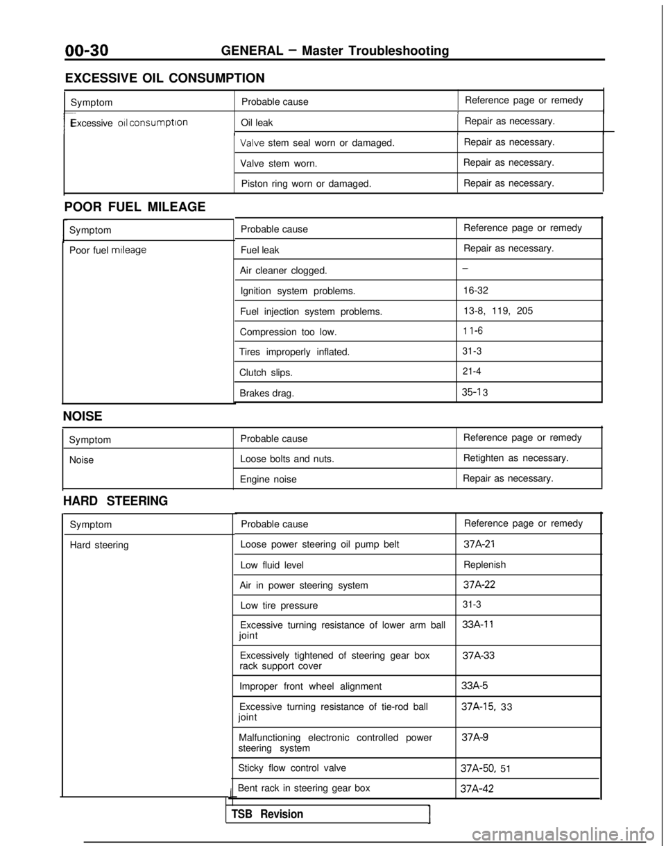
00-30GENERAL - Master Troubleshooting
EXCESSIVE OIL CONSUMPTION Symptom Probable cause Reference page or remedy
1
r-Excessive 011 consumption
Oil leak Repair as necessary.I Valve
stem seal worn or damaged. Repair as necessary.
Valve stem worn. Repair as necessary.
Piston ring worn or damaged. Repair as necessary.
POOR FUEL MILEAGE Symptom
Poor fuel mtleage
Probable cause
Fuel leak
Air cleaner clogged. Ignition system problems.
Fuel injection system problems.
Compression too low.
Tires improperly inflated.
Clutch slips.Brakes drag. Reference page or remedy
Repair as necessary.
-
16-32
13-8, 119, 205
1 l-6
31-3 21-4
35-l 3
NOISE
SymptomNoise Probable cause
Loose bolts and nuts.
Engine noise Reference page or remedy
Retighten as necessary.
Repair as necessary.
HARD STEERING
Symptom
Hard steering Probable cause
Reference page or remedy
Loose power steering oil pump belt
37A-21
Low fluid level Replenish
Air in power steering system
37A-22
Low tire pressure31-3
Excessive turning resistance of lower arm ball33A-11
joint Excessively tightened of steering gear box 37A-33
rack support cover
Improper front wheel alignment
Excessive turning resistance of tie-rod ball
joint
Malfunctioning electronic controlled power
steering system
Sticky flow control valve
Bent rack in steering gear box
J
TSB RevisionI
33A-5
37A-15, 33 37A-9
37A-50,
51 37A-42
Page 33 of 1273
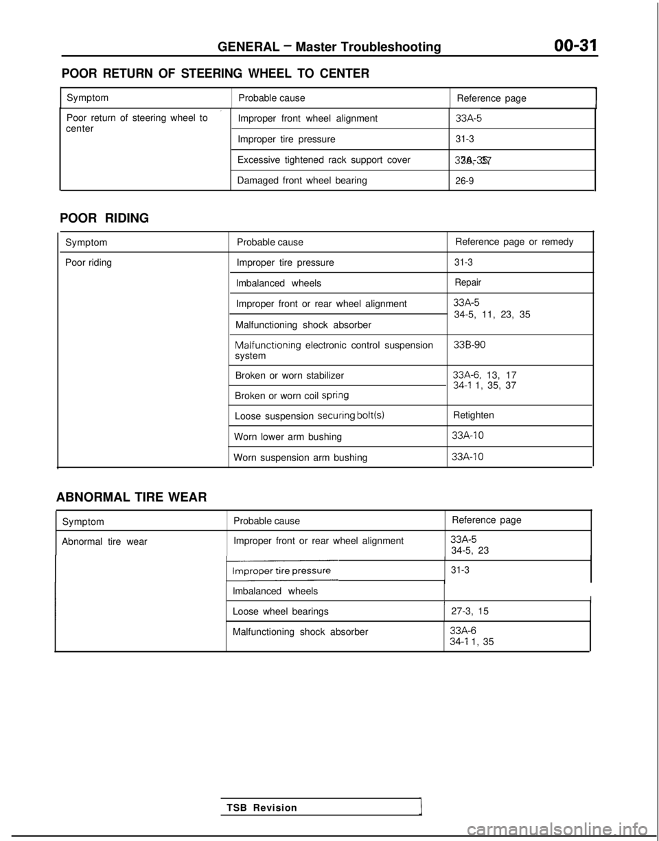
GENERAL - Master Troubleshooting
00-31
POOR RETURN OF STEERING WHEEL TO CENTER
Symptom
Probable cause Reference page
’Poor return of steering wheel to
Improper front wheel alignment33A-5center
Improper tire pressure31-3
Excessive tightened rack support cover 37A-35, 36, 37
Damaged front wheel bearing
26-9
POOR RIDING
Symptom
Poor riding Probable cause
Reference page or remedy
Improper tire pressure
31-3
lmbalanced wheelsRepair
Improper front or rear wheel alignment33A-5
34-5, 11, 23, 35
Malfunctioning shock absorber Malfunctioning
electronic control suspension
33B-90system
Broken or worn stabilizer
33A-6. 13, 1734-l 1, 35, 37
Broken or worn coil spri#ng
Loose suspension secuiring bolt(s)
Retighten
Worn lower arm bushing
33A-10
Worn suspension arm bushing 33A-IO
TSB Revision
ABNORMAL TIRE WEAR
Symptom
Abnormal tire wear Probable cause
Improper front or rear wheel alignment Reference page
33A-534-5, 23
131-3
lmbalanced wheelsII
Loose wheel bearings
27-3, 15
Malfunctioning shock absorber
33A-634-l 1, 35