1989 MITSUBISHI GALANT width
[x] Cancel search: widthPage 25 of 1273
GENERAL - General Data and Specifications00-23
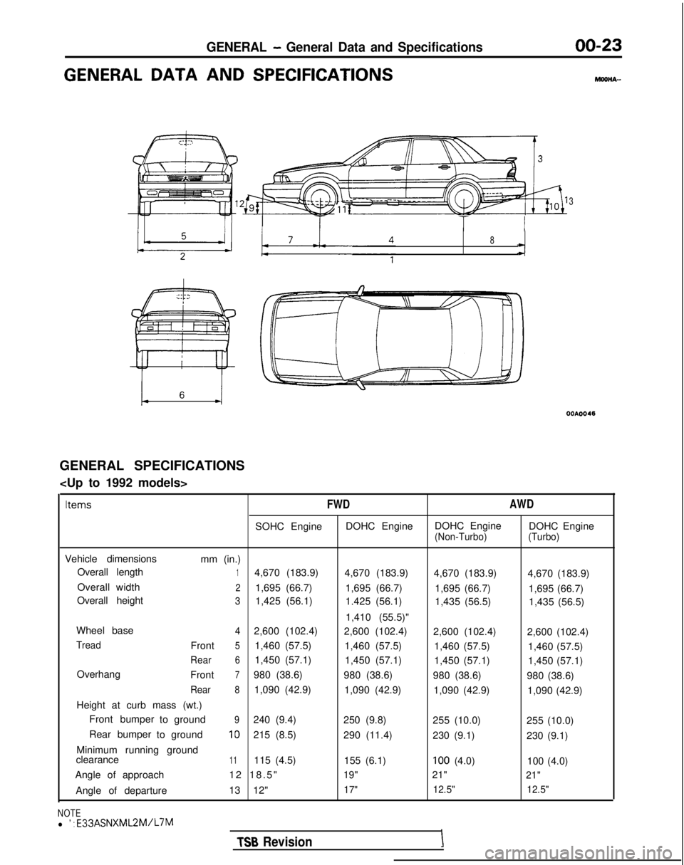
GENERAL DATA AND SPECIFICATIONSMOOHA-
3
I TT I
8
GENERAL SPECIFICATIONS
FWD
AWD
SOHC EngineDOHC EngineDOHC Engine
DOHC Engine(Non-Turbo) (Turbo)
Vehicle dimensions
mm (in.)
Overall length
14,670 (183.9) 4,670 (183.9)4,670 (183.9) 4,670 (183.9)
Overall width
21,695 (66.7) 1,695 (66.7)1,695 (66.7) 1,695 (66.7)
Overall height
31,425 (56.1) 1.425 (56.1)1,435 (56.5) 1,435 (56.5)
1,410 (55.5)"
Wheel base
42,600 (102.4) 2,600 (102.4)2,600 (102.4) 2,600 (102.4)
TreadFront51,460 (57.5)1,460 (57.5)1,460 (57.5) 1,460 (57.5)
Rear61,450 (57.1)1,450 (57.1)1,450 (57.1) 1,450 (57.1)
Overhang Front
7980 (38.6)980 (38.6)980 (38.6) 980 (38.6)
Rear81,090 (42.9)1,090 (42.9)1,090 (42.9) 1,090 (42.9)
Height at curb mass (wt.) Front bumper toground
9240 (9.4)
250 (9.8)255 (10.0) 255 (10.0)
Rear bumper toground
10215 (8.5)
290 (11.4)230 (9.1) 230 (9.1)
Minimum running ground
clearance
11115 (4.5) 155 (6.1)100 (4.0)100 (4.0)
Angle of approach 12 18.5
"
19"21"21"
Angle of departure
13 12"17"12.5"
12.5"
NOTEl ’ : E33ASNXML2M/L7M
TSB RevisionI
Page 27 of 1273
GENERAL - General Data and Specifications00-25
(1993 models
>
Items
FWD
SOHC Engine DOHC Engine
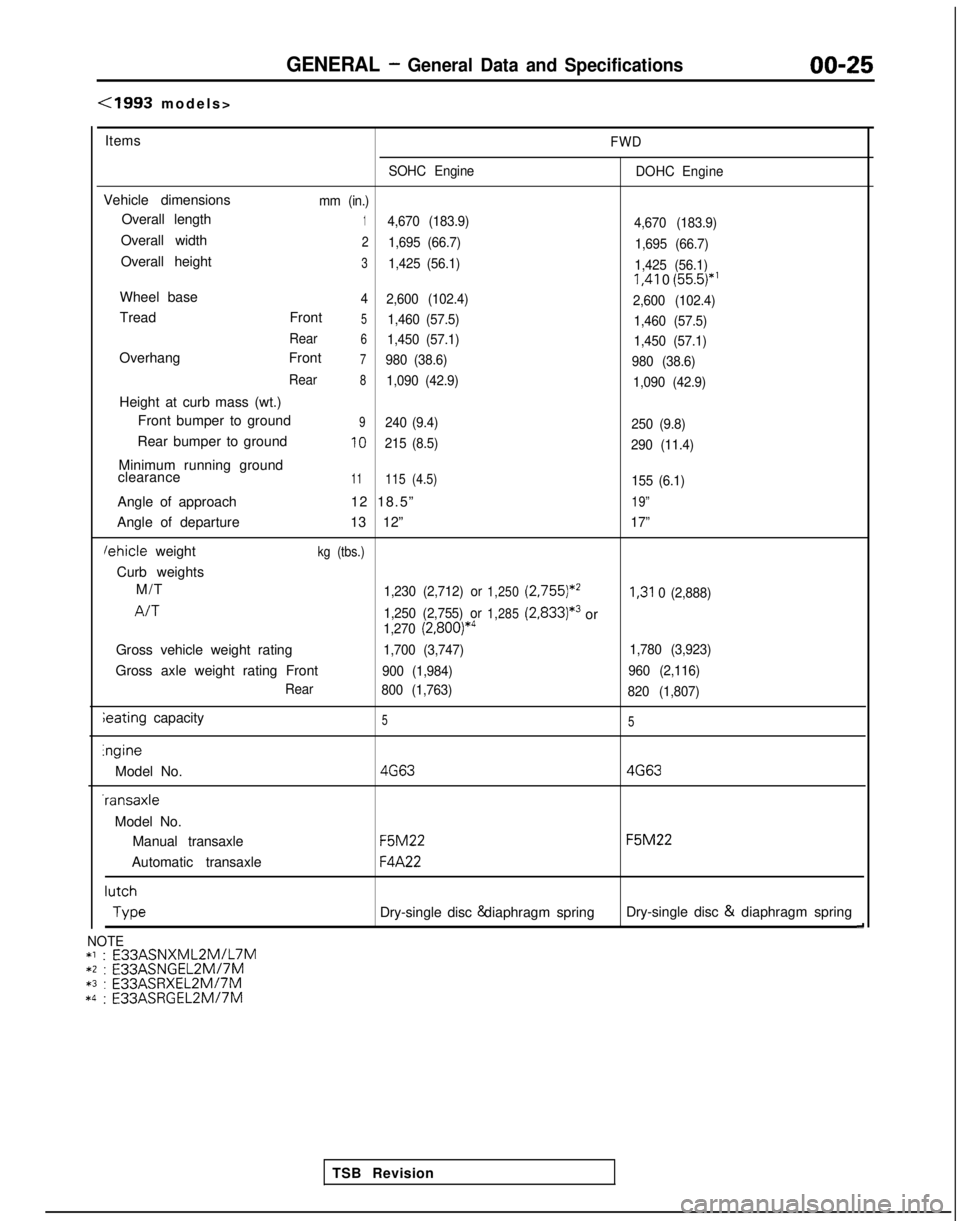
Vehicle dimensionsmm (in.)
Overall length14,670 (183.9)
4,670 (183.9)
Overall width21,695 (66.7)1,695 (66.7)
Overall height31,425 (56.1)1,425 (56.1) I,41
0
(55.5)*’
Wheel base4
2,600 (102.4)
2,600 (102.4)
Tread Front51,460 (57.5)1,460 (57.5)
Rear
61,450 (57.1) 1,450 (57.1)
Overhang Front7980 (38.6)980 (38.6)
Rear
81,090 (42.9) 1,090 (42.9)
Height at curb mass (wt.)
Front bumper to ground
9240 (9.4) 250 (9.8)
Rear bumper to ground10215 (8.5)290 (11.4)
Minimum running ground
clearance11115 (4.5)155 (6.1)
Angle of approach 12 18.5”19”
Angle of departure13 12”17”
lehicle weightkg (tbs.)
Curb weights
M/T
1,230 (2,712) or1,250 (2,755)*’I,31
0 (2,888)
A/T1,250 (2,755) or1,285(2,833)*3or1,270 (2,800)*4
Gross vehicle weight rating1,700 (3,747) 1,780 (3,923)
Gross axle weight rating Front900 (1,984)960 (2,116)
Rear 800 (1,763)
820 (1,807)
ieating capacity55lngine
Model No.
4G634G63 -ransaxle
Model No. Manual transaxle
F5M22 F5M22
Automatic transaxle
F4A22 lutch
Type
Dry-single disc & diaphragm spring
Dry-single disc &
diaphragm spring
d
TSB Revision
NOTE*l : E33ASNXML2MlL7M*2 : E33ASNGEL2MI7M*3 :
E33ASRXEL2M/7M*4 :
E33ASRGEL2M/7M
Page 88 of 1273
11-38
ENGINE
Rubber
exposed
Tooth missing
and
canvas fiber exposed
lEN0002
Crankshaft
sprocket “B”
Crankshaft
aENzo4
Spacer
Chamfered
6EN009
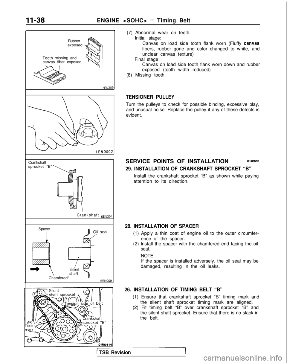
(7) Abnormal wear on teeth.Initial stage:Canvas on load side tooth flank worn (Fluffy canvas
fibers, rubber gone and color changed to white, and unclear canvas texture)
Final stage: Canvas on load side tooth flank worn down and rubber
exposed (tooth width reduced)
(8) Missing tooth.
TENSIONER PULLEY
Turn the pulleys to check for possible binding, excessive play, and unusual noise. Replace the pulley if any of these defects is
evident.
SERVICE POINTS OF INSTALLATION
MllKDCE
29. INSTALLATION OF CRANKSHAFT SPROCKET “B”
Install the crankshaft sprocket “B” as shown while paying
attention to its direction.
28. INSTALLATION OF SPACER
(1) Apply a thin coat of engine oil to the outer circumfer-
ence of the spacer.
(2) Install the spacer with the chamfered end facing the oil
seal.
NOTE
If the spacer is installed adversely, the oil seal may be
damaged, resulting in the oil leaks.
26. INSTALLATION OF TIMING BELT “B”
(1) Ensure that crankshaft sprocket “B” timing mark and the silent shaft sprocket timing mark are aligned.
(2) Fit timing belt “B” over crankshaft sprocket “B” and
the silent shaft sprocket. Ensure that there is no slack in
the belt.
1 TSB Revision
Page 96 of 1273
. .CrackII-46ENGINE
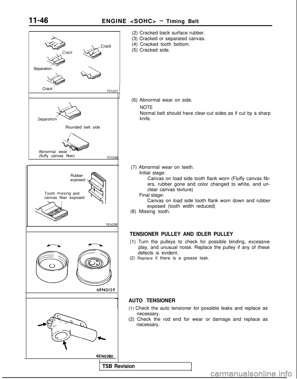
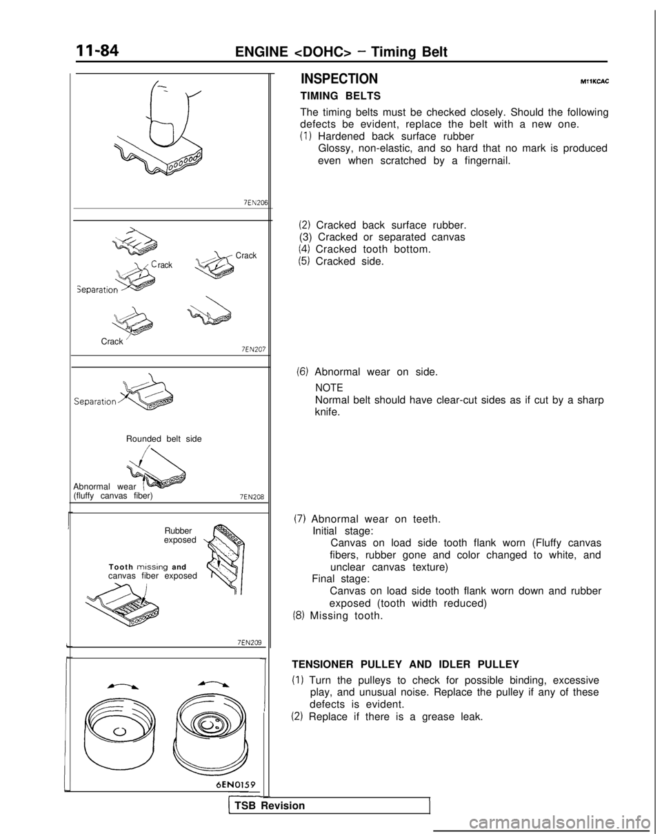
(2) Cracked back surface rubber.
(3) Cracked or separated canvas.
(4) Cracked tooth bottom.
(5) Cracked side.
Separation
Crack
’7EN207
Rounded belt side
Abnormal wear (fluffy canvas fiber)
7EN208
Rubber
exposed
Tooth mlsslng
and
canvas fiber exposed
7EN209
6EN0159
c \/Ga//
@E3%00
t 6EN0280(6) Abnormal wear on side.
NOTE
Normal belt should have clear-cut sides as if cut by a sharp
knife.
(7) Abnormal wear on teeth.
Initial stage:Canvas on load side tooth flank worn (Fluffy canvas fib-
ers, rubber gone and color changed to white, and un-
clear canvas texture)
Final stage: Canvas on load side tooth flank worn down and rubber
exposed (tooth width reduced)
(8) Missing tooth.
TENSIONER PULLEY AND IDLER PULLEY
(1) Turn the pulleys to check for possible binding, excessive
play, and unusual noise. Replace the pulley if any of these
defects is evident.
(2) Replace if there is a grease leak.
AUTO TENSIONER
(1) Check the auto tensioner for possible leaks and replace as
necessary.
(2) Check the rod end for wear or damage and replace as necessary.
TSB Revision
Page 134 of 1273
11-84
ENGINE
QdiJ00°00B
rackCrack
Crack ’ 7EN207
Separation
Rounded belt side
Abnormal wear (fluffy canvas fiber)
7EN208
Rubber
exposed
Tooth
missing and
canvas fiber exposed
7EN209
6EN0159
Y
1
-
INSPECTION
TIMING BELTS MIlKCAC
The timing belts must be checked closely. Should the following
defects be evident, replace the belt with a new one.
(1) Hardened back surface rubber Glossy, non-elastic, and so hard that no mark is produced
even when scratched by a fingernail.
(2) Cracked back surface rubber.
(3) Cracked or separated canvas
(4) Cracked tooth bottom.
(5) Cracked side.
(6) Abnormal wear on side.
NOTE
Normal belt should have clear-cut sides as if cut by a sharp
knife.
(7) Abnormal wear on teeth. Initial stage: Canvas on load side tooth flank worn (Fluffy canvas
fibers, rubber gone and color changed to white, and unclear canvas texture)
Final stage:
Canvas on load side tooth flank worn down and rubber
exposed (tooth width reduced)
(8) Missing tooth.
TENSIONER PULLEY AND IDLER PULLEY
(1) Turn the pulleys to check for possible binding, excessive play, and unusual noise. Replace the pulley if any of these
defects is evident.
(2) Replace if there is a grease leak.
I1 TSB Revision
Page 798 of 1273
23-92AUTOMATIC TRANSAXLE - Service Adjustment Procedures
NOTE
When adjusting the reducing pressure, aim for the center
value (425 kPa, 60 psi) of the standard value allowance.
Standard value: 415-435
kPa (59-62 psi)
Oil pressure change for each turn of adjustment screw: 22
kPa (3.1 psi) . . . FWD (Up to MODEL 1990)
45
kPa (6.4 psi) . . . FWD (From MODEL 1990.5, AWD)
3. Install the oil filter and oil pan in the same way as for adjustment of the line pressure.
4. Make the oil pressure test. Readjust if necessary.
(If the scan tool is used)
1. Using the scan tool, forcibly drive the pressure control
solenoid valve at 50% duty, and measure the kick-down
brake apply pressure.
If the kick-down brake apply pressure does not exist within
the standard value width, adjust the pressure with the
reducing pressure adjustment screw.
Standard value: 275 + 10 kPa (39 + 1 psi)
Oil pressure change for each turn of adjustment screw:
25 kPa (3.6 psi) FWD (Up to MODEL 1990)
22
kPa (3.1 psi) FWD (From MODEL 1990.5), AWD
2. Check to be sure that the reducing pressure (after the
adjustment is completed) is within the range of 360-480
kPa (51 -68 psi.).
Caution
This adjustment should be made at an oil
temperature
of 70- 80°C
(160- 180°F).
If the adjustment is made at a temperature that is too
high, the line pressure will drop during idling, with the
result that it might not be possible to make the correct
adjustment.
I / Oii
seal09K561
THROTTLE-POSITION SENSOR ADJUSTMEF&
Refer to GROUP 13-On-Vehicle Inspection of MFI Compo-
nents.
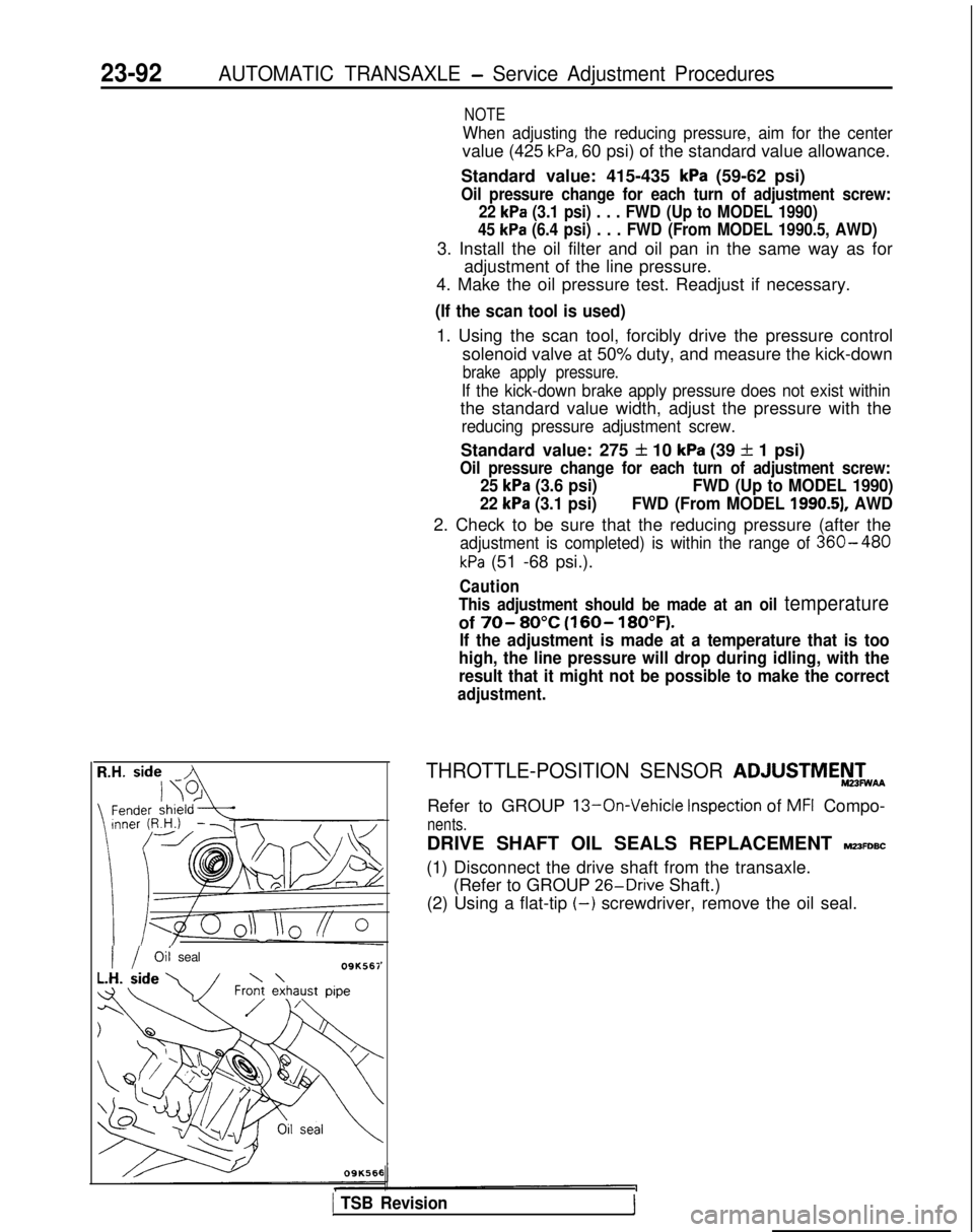
DRIVE SHAFT OIL SEALS REPLACEMENT MZ3FDBC
(1) Disconnect the drive shaft from the transaxle. (Refer to GROUP 26-Drive
Shaft.)
(2) Using a flat-tip
(-) screwdriver, remove the oil seal.
1 TSB Revision1
Page 848 of 1273
26-18FRONT AXLE - Drive Shaft (T.J.-R.J.
Type)
(7) For the boot band (small), cut away so that the length
of the band width remains, and then bend it over the
crimped band fitting.
For the boot band (large), cut away so that the length
until the clip holder position remains, and then secure
by the clip.
Fitting 32.3kO.3
mm
(I .27 t .Ol in.) llR0052
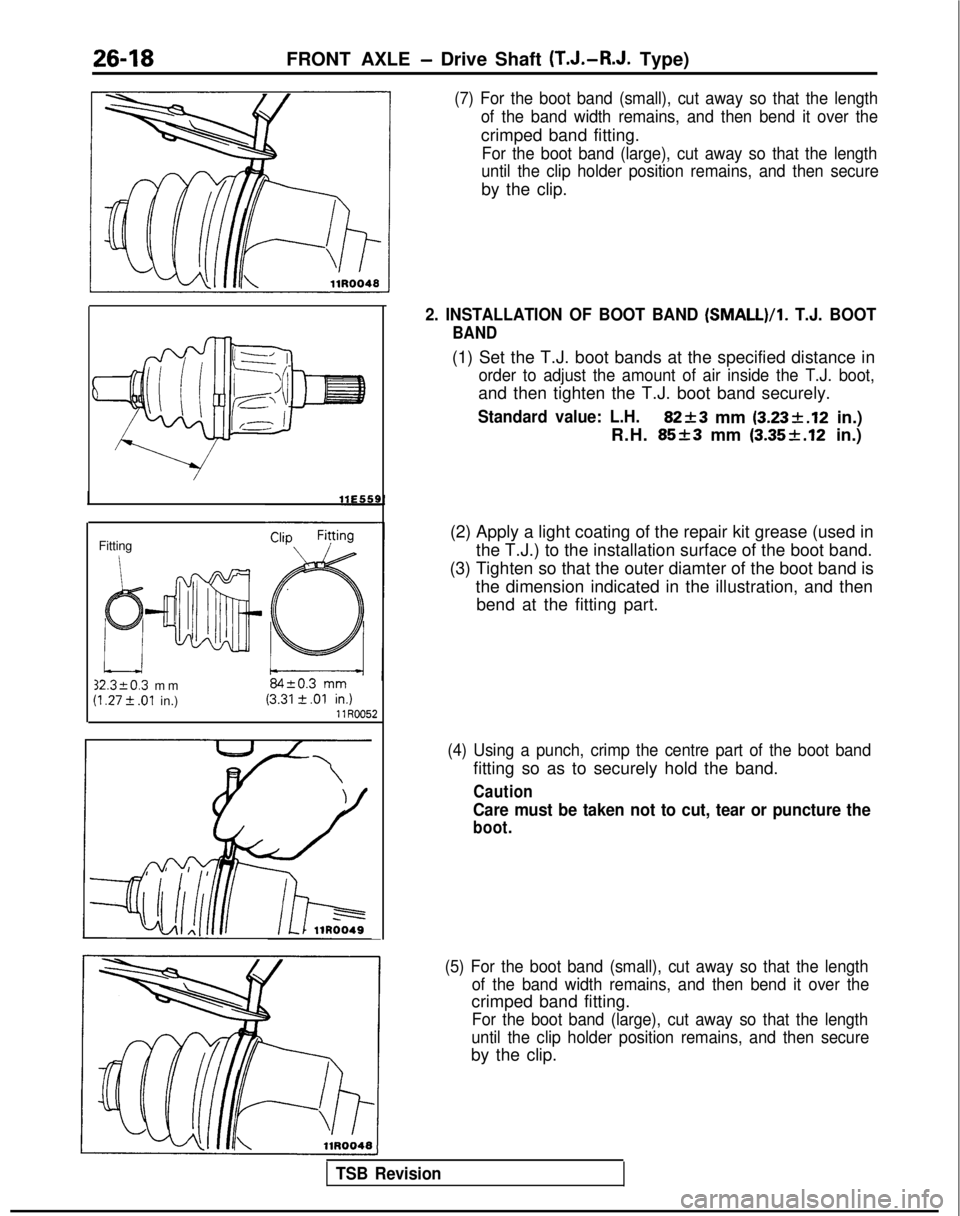
2. INSTALLATION OF BOOT BAND (SMALL)/l.
T.J. BOOT
BAND
(1) Set the T.J. boot bands at the specified distance in
order to adjust the amount of air inside the T.J. boot,
and then tighten the T.J. boot band securely.
Standard value: L.H.82+3 mm (3.23k.12
in.)
R.H.
85+3 mm (3.35f.12 in.)
(2) Apply a light coating of the repair kit grease (used in the T.J.) to the installation surface of the boot band.
(3) Tighten so that the outer diamter of the boot band is the dimension indicated in the illustration, and thenbend at the fitting part.
(4) Using a punch, crimp the centre part of the boot band
fitting so as to securely hold the band.
Caution
Care must be taken not to cut, tear or puncture the
boot.
(5) For the boot band (small), cut away so that the length of the band width remains, and then bend it over the
crimped band fitting.
For the boot band (large), cut away so that the length
until the clip holder position remains, and then secure
by the clip.
TSB Revision
Page 1190 of 1273
SERVICE BRAKES - Service Adjustment Procedures35-69
(5) The probable cause if the output voltage is 50 mV or lower, or if the one-side deflection width of the
oscilloscope’s waveform is 70
mV or lower
Probable causes Remedy
Excessive clearance between the speed sensor pole
piece and rotor Adjust to the standard value.
Foreign material attached to the speed sensor pole
pieceRemove the foreign material.
Damaged speed sensor pole pieceReplace the speed sensor.
Damaged rotor teeth~~~ rReplace the rotor.
Loose speed sensor or rotor installation bolt I
Tighten to the specified torque.
1
NOTE
The speed sensor internal resistance and harness side are normal.
Caution
It is conceivable, because the movement of a speed-sensor cable “foll\
ows” the movement of the front
or rear suspension, that the damaged wiring condition may be apparent on\
ly during travel on poor
road surfaces, and may be normal on better road surfaces. Therefore, whe\
n measuring the output
voltage of a speed sensor, recheck the condition of the cable connection\
s by removing the clamp and pulling the cable and bending it near the clamp position in order to che\
ck for the existence of damaged
wiring.
1/21314j51617)61Q~10~11~12)13~14~15)16~17~1~~19~20~21~22~23~24~25~26(27~26~2Q~30(31~32~33~34~35~
Check connector
74=f=n
ECU
*
Body harnessMB991 356fl 14N018C
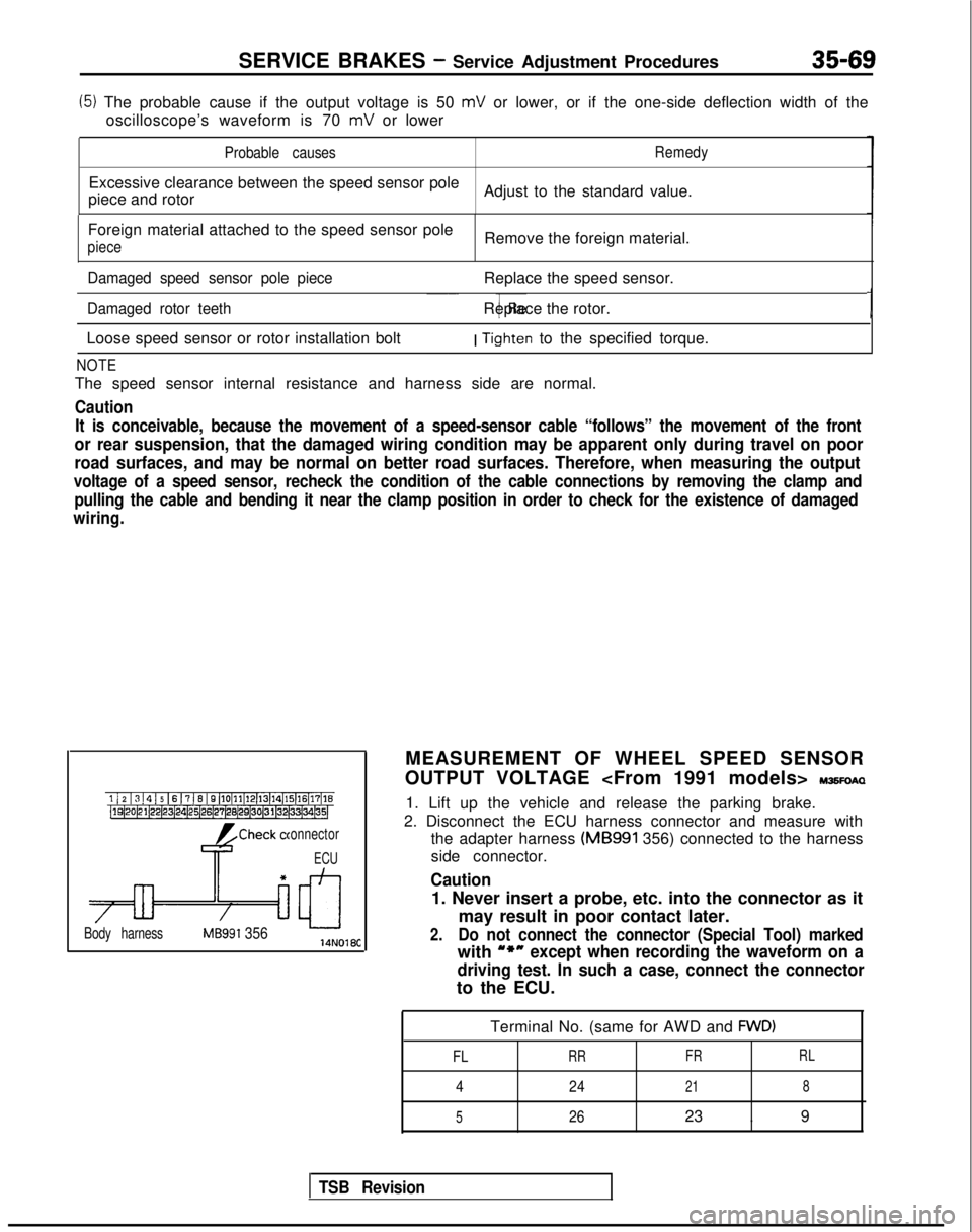
MEASUREMENT OF WHEEL SPEED SENSOR
OUTPUT VOLTAGE
IWSFOAQ
1. Lift up the vehicle and release the parking brake.
2. Disconnect the ECU harness connector and measure with the adapter harness (MB991
356) connected to the harness
side connector.
Caution
1. Never insert a probe, etc. into the connector as it
may result in poor contact later.
2.Do not connect the connector (Special Tool) marked
with u*nexcept when recording the waveform on a
driving test. In such a case, connect the connector
to the ECU.
Terminal No. (same for AWD and
FWD)
FL
RR FRRL
4
24218
5
2623 . 9
TSB Revision