Page 62 of 1273
11-12ENGINE - Service Adjustment Procedures
DRIVE BELTS TENSION ADJUSTMENT
MllFMBBO
(1) Check that the belts are not damaged.
Power steenng
oil pump
pulley
\
W
ater
pump
pulley
I Tension
pulley/
Generator
compressor
Crankshaft
pulley pulley
We
Spindle----As.
IRESET button (2) Apply
IOON (22 Ibs.) force to the belt back midwa
y
between the pulleys as shown in the figure, measure the
deflection or, by using a belt-tension gauge, check the
belt’s tension.
Standard value:
Gauge250-500500-700400 (88)
N (Ibs.)(55-110)(110-154)
ForAKDeflection Approx. 8.05.0-5.56.0-7.0
compressor mm (in.)(.315)(.197-,217) (.236-.276)
For P/S
pump Gauge
250-500320-400470-570
N (Ibs.)(55-110)(71-88)(104-126)
Deflection 6.0-9.0
-mm (in.)(.236-,354)
NOTE
There is more than one type of belt-tension gauge (type A and
type
8, for example), so be sure to use the gauge according to
its instructions for use.
1 TSB Revision
Page 111 of 1273
ENGINE - Service Adjustment Procedures11-61
DRIVE BELTS TENSION ADJUSTMENT
MllFMBBl
(1) Check that the belts are not damaged.
Power
steering
oil pump
pulley , W
ater
pump
pulley
Tension
pulley
f /
xI J
b
L ‘d
p1 Genkrator
I
Ipulley
Crankshaft
Air
pulley conditioning
compressor
pulley
Spindle Spindle
2Y
\Hook
xi@--
V-ribbed belt
Hook
r
Type BRESET button (2) Apply
100N (22 Ibs.) force to the belt back midwa
y
between the pulleys as shown in the figure, measure the
deflection or, by using a belt-tension gauge, check the
belt’s tension.
Standard value:
Items
For
AKDeflection Approx. 8.05.0-5.56.0-7.0
comDressormm (in.)t.3151(.197-,217) (.236-.276)I
NOTE
There is more than one type of belt-tension gauge (type A and
type
B, for example), so be sure to use the gauge according to
its instructions for use.
1 TSB Revision
Page 353 of 1273

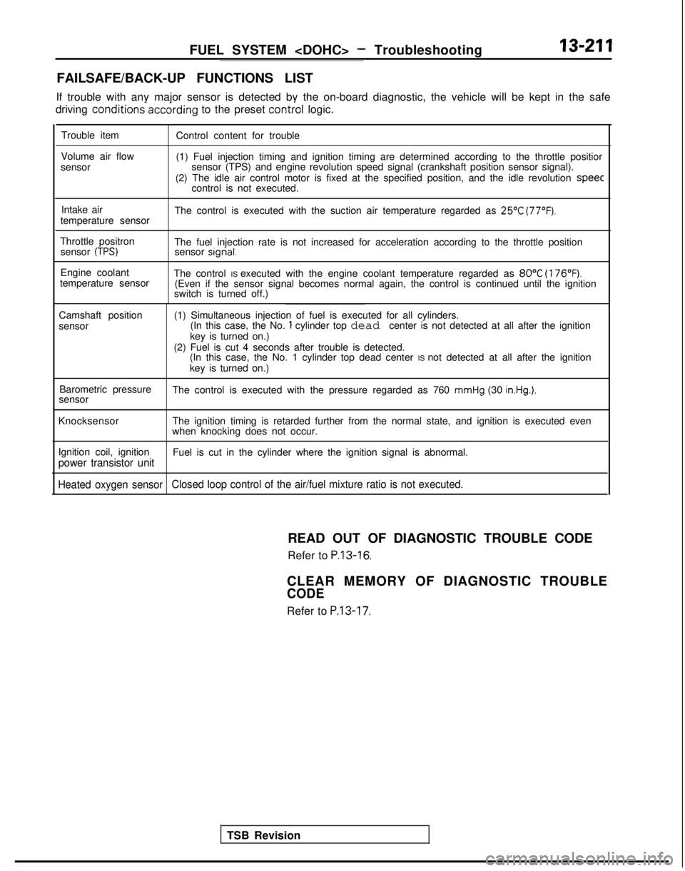
FUEL SYSTEM - Troubleshooting13-211
FAILSAFE/BACK-UP FUNCTIONS LIST
If trouble with any major sensor is detected by the on-board diagnostic,\
the vehicle will be kept in the safe
driving conditions-accdrding
to the preset control
logic.
Trouble item
Volume air flow
sensor Control content for trouble
(1) Fuel injection timing and ignition timing are determined according\
to the throttle positior
sensor (TPS) and engine revolution speed signal (crankshaft position \
sensor signal).
(2) The idle air control motor is fixed at the specified position, and\
the idle revolution speec
control is not executed.
Intake air
temperature sensor The control is executed with the suction air temperature regarded as
25’C (77°F).
Throttle positron
sensor (TPS)The fuel injection rate is not increased for acceleration according to t\
he throttle positionsensor signal.
Engine coolant
temperature sensor The control IS executed with the engine coolant temperature regarded as 80°C
(176°F).(Even if the sensor signal becomes normal again, the control is continu\
ed until the ignition
switch is turned off.)
Camshaft position
sensor (1) Simultaneous injection of fuel is executed for all cylinders.
(In this case, the No.
1 cylinder top dead center is not detected at all after the ignition
key is turned on.)
(2) Fuel is cut 4 seconds after trouble is detected. (In this case, the No. 1 cylinder top dead center IS not detected at all after the ignition
key is turned on.)
Barometric pressure
sensor The control is executed with the pressure regarded as 760
mmHg (30 in.Hg.).
Knocksensor
The ignition timing is retarded further from the normal state, and ignit\
ion is executed even
when knocking does not occur.
Ignition coil, ignition
power transistor unitFuel is cut in the cylinder where the ignition signal is abnormal.
Heated oxygen sensor Closed loop control of the air/fuel mixture ratio is not executed.
TSB RevisionREAD OUT OF DIAGNOSTIC TROUBLE CODE
Refer to
P.13-16.
CLEAR MEMORY OF DIAGNOSTIC TROUBLE
CODE
Refer to P.13-17.
Page 403 of 1273

FUEL SYSTEM -On-Vehicle inspection of MFI Components13-261
VOLUME AIR FLOW SENSORMlWFAAs
/
side
@Harness side connector
I@ Harness sideconnector
Fnnine control module connector
Multiport fuel
The area enclosed with :I: is injection relay
applicable only for Turbo vehicle.
I
@I Component connector (Filter reset circuit)
Engine control module
6FU1537
Intake air amount (Wsec)
162451
OlLO838
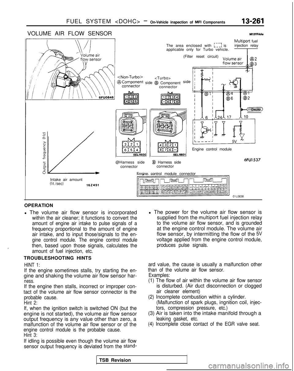
OPERATION
l The volume air flow sensor is incorporated
within the air cleaner; it functions to convert the
amount of engine air intake to pulse signals of a
frequency proportional to the amount of engine air intake, and to input those/signals to the en-
gine control module. The engine control module
then, based upon those signals, calculates the
amount of fuel injection, etc.
TROUBLESHOOTING HINTS
HINT 1:
If the engine sometimes stalls, try starting the en-
gine and shaking the volume air flow sensor har-
ness.
If the engine then stalls, incorrect or improper con-
tact of the volume air flow sensor connector is the
probable cause.
Hint 2:
If, when the ignition switch is switched ON (but the
engine is not started), the volume air flow sensor
output frequency is any value other than zero, a
malfunction of the volume air flow sensor or of the
engine control module is the probable cause.
Hint 3:
If idling is possible even though the volume air flow
sensor output frequency is deviated from the
stand-
l The power for the volume air flow sensor is supplied from the
multiport fuel injection relay
to the volume air flow sensor, and is grounded
at the engine control module. The volume air
flow sensor, by intermitting the flow of the
5V
voltage applied from the engine control module,
produces pulse signals.
ard value, the cause is usually a malfunction other
than of the volume air flow sensor. Examples:
(1) The flow of air within the volume air flow sensor
is disturbed. (Air duct disconnection or clogged
air cleaner element)
(2) Incomplete combustion within a cylinder.(Malfunction of spark plugs, ingnition coil, injec-
tors, compression pressure, etc.)
(3) Air is taken into the intake manifold through a
leaking gasket, etc.
(4) Incomplete close contact of the EGR valve seat.
TSB Revision