1989 MITSUBISHI GALANT key battery
[x] Cancel search: key batteryPage 153 of 1273
FUEL SYSTEM
ON-BOARD DIAGNOSTIC-
The engine control module monitors the input/out-
put signals (some signals at all times and the others
under specified conditions) of the engine control
module.
When it is noticed that an irregularity has continued
for a specified time or longer from when the irregu- lar signal is initially monitored, passing a certain
number, the engine control module judges that an
irregularity has occurred, memorizes the diagnostic
trouble code, and outputs the signal to the on-board
diagnostic output terminal.
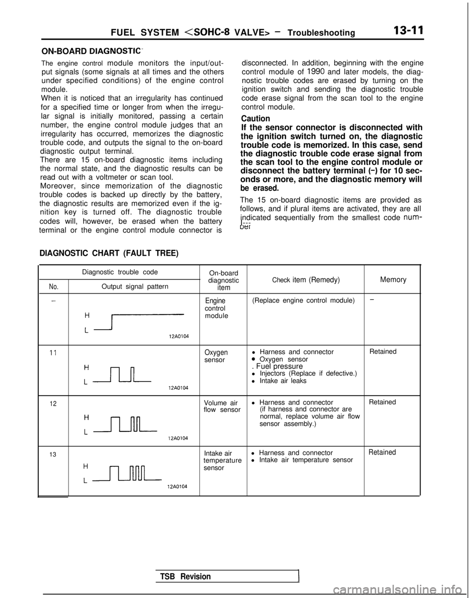
There are 15 on-board diagnostic items including
the normal state, and the diagnostic results can be
read out with a voltmeter or scan tool.
Moreover, since memorization of the diagnostic
trouble codes is backed up directly by the battery,
the diagnostic results are memorized even if the ig- nition key is turned off. The diagnostic trouble
codes will, however, be erased when the battery disconnected. In addition, beginning with the engine
control module of
1990 and later models, the diag-
nostic trouble codes are erased by turning on the
ignition switch and sending the diagnostic trouble
code erase signal from the scan tool to the engine
control module.
Caution
If the sensor connector is disconnected with
the ignition switch turned on, the diagnostic
trouble code is memorized. In this case, send
the diagnostic trouble code erase signal from
the scan tool to the engine control module or disconnect the battery terminal (-)
for 10 sec-
onds or more, and the diagnostic memory will
be erased.
The 15 on-board diagnostic items are provided as
follows, and if plural items are activated, they are all
indicated sequentially from the smallest code num-
I---
terminal or the engine control module connector is
uer
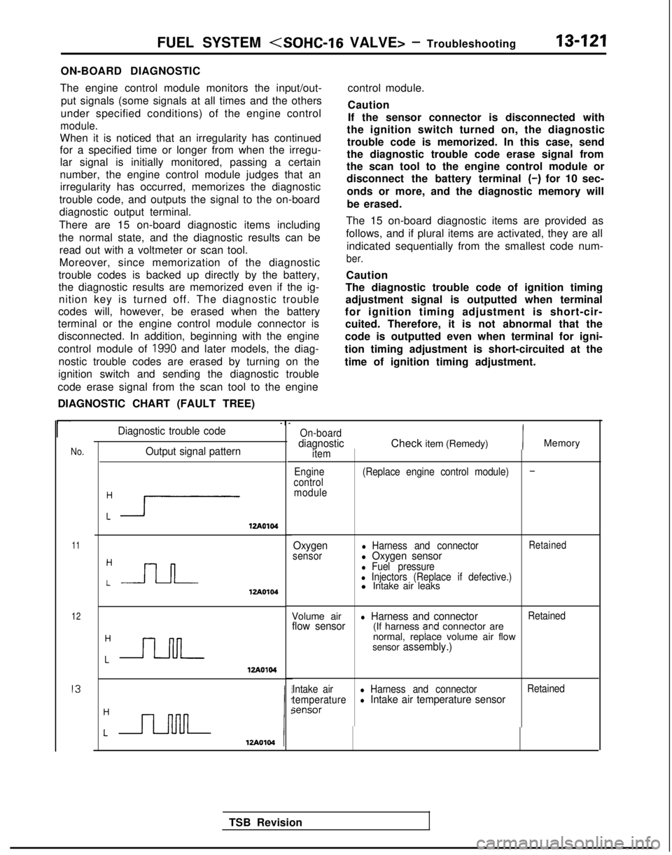
DIAGNOSTIC CHART (FAULT TREE)
No.
-
Diagnostic trouble code On-board
diagnostic
Check item (Remedy) MemoryOutput signal patternitem
-Engine(Replace engine control module)
control
:r
module 12A0104
11Oxygenl Harness and connector
Retained
sensor0 Oxygen sensor
:-JLJ--
. Fuel pressure
l Injectors (Replace if defective.)
l Intake air leaks 12A0104
12Volume air
l Harness and connector
Retained
flow sensor (if harness and connector are
:-JJ-M-
normal, replace volume air flow
sensor assembly.) 12A0104
13 Intake air
l Harness and connector
Retained
temperature l Intake air temperature sensor
:n
sensor 12A0104
TSB Revision
Page 158 of 1273
13-16
FUEL SYSTEM
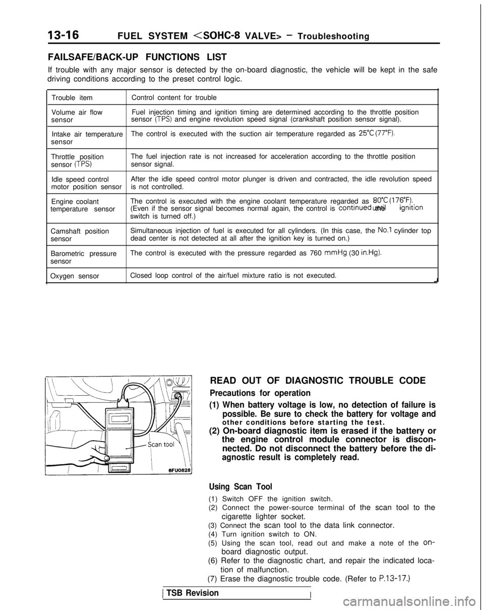
FAILSAFE/BACK-UP FUNCTIONS LIST
If trouble with any major sensor is detected by the on-board diagnostic,\
the vehicle will be kept in the safe
driving conditions according to the preset control logic.
Trouble item Control content for trouble
Volume air flow Fuel injection timing and ignition timing are determined according to th\
e throttle position
sensor sensor
(TPS) and engine revolution speed signal (crankshaft position sensor signal)\
.
Intake air temperature The control is executed with the suction air temperature regarded as
25°C (77°F).
sensor
Throttle position The fuel injection rate is not increased for acceleration according to t\
he throttle position
sensor
(TPS)sensor signal.
Idle speed control After the idle speed control motor plunger is driven and contracted, the\
idle revolution speed
motor position sensor is not controlled.
Engine coolant The control is executed with the engine coolant temperature regarded as \
8OO.C (176°F).temperature sensor (Even if the sensor signal becomes normal again, the control is continued
until the ignltlon
switch is turned off.)
Camshaft position Simultaneous injection of fuel is executed for all cylinders. (In this \
case, the
No.1 cylinder top
sensor dead center is not detected at all after the ignition key is turned on.)\
Barometric pressure The control is executed with the pressure regarded as 760 mmHg
(30
in.Hg).
sensor
Oxygen sensor Closed loop control of the air/fuel mixture ratio is not executed.
i
READ OUT OF DIAGNOSTIC TROUBLE CODE
Precautions for operation
(1) When battery voltage is low, no detection of failure is possible. Be sure to check the battery for voltage and
other conditions before starting the test.
(2) On-board diagnostic item is erased if the battery or the engine control module connector is discon-
nected. Do not disconnect the battery before the di-
agnostic result is completely read.
Using Scan Tool
(1) Switch OFF the ignition switch.
(2) Connect the power-source terminal of the scan tool to the
cigarette lighter socket.
(3) Connect the scan tool to the data link connector. (4) Turn ignition switch to ON.
(5) Using the scan tool, read out and make a note of the
on-
board diagnostic output.
(6) Refer to the diagnostic chart, and repair the indicated loca-
tion of malfunction.
(7) Erase the diagnostic trouble code. (Refer to
P.13-17.)
1 TSB RevisionI
Page 159 of 1273
FUEL SYSTEM
\ I\-\\\\\\6FUO807
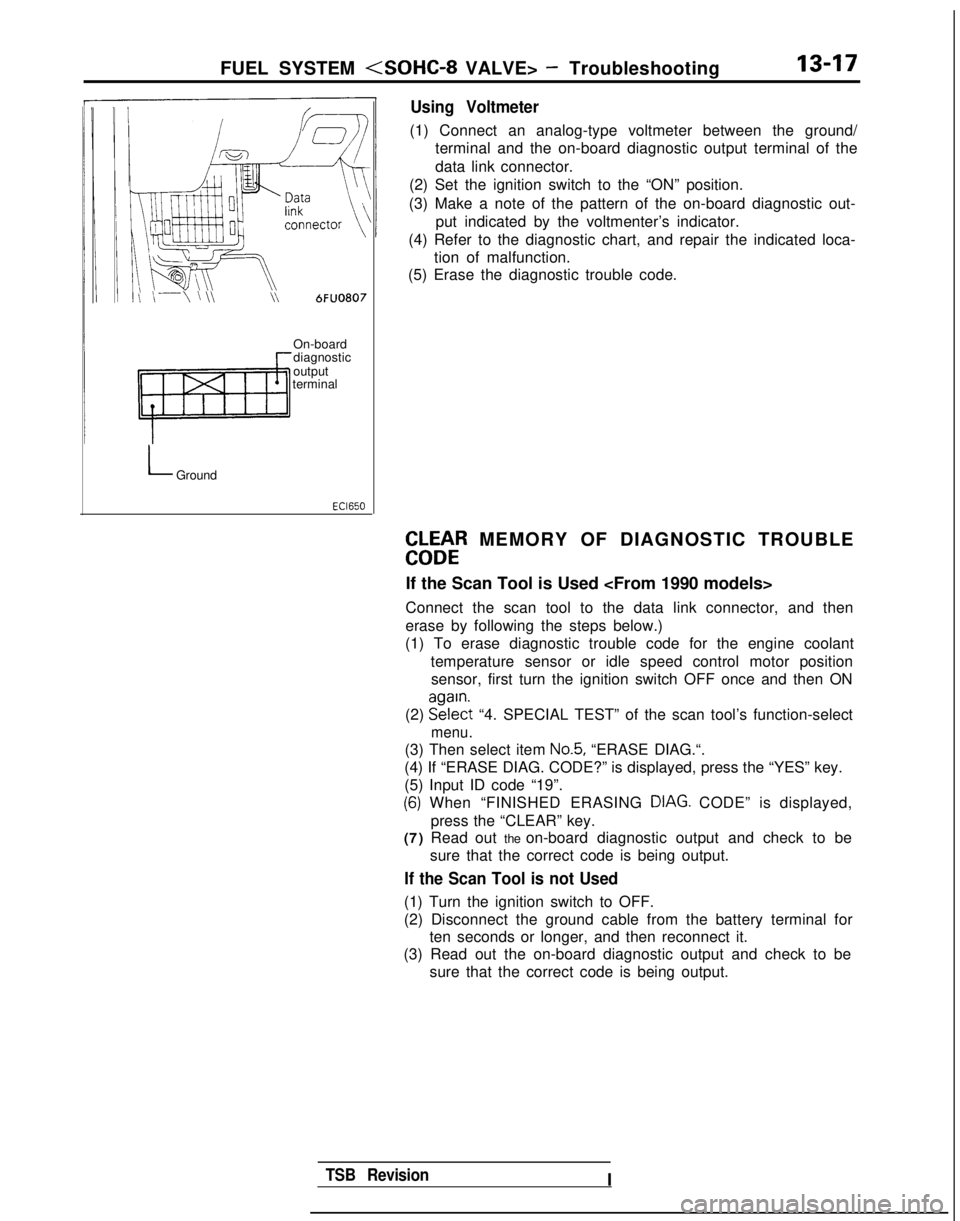
Using Voltmeter
(1) Connect an analog-type voltmeter between the ground/
terminal and the on-board diagnostic output terminal of the
data link connector.
(2) Set the ignition switch to the “ON” position.
(3) Make a note of the pattern of the on-board diagnostic out- put indicated by the voltmenter’s indicator.
(4) Refer to the diagnostic chart, and repair the indicated loca- tion of malfunction.
(5) Erase the diagnostic trouble code.
On-board
diagnostic
output
terminal
LGround
EbLbtR MEMORY OF DIAGNOSTIC TROUBLE
If the Scan Tool is Used
Connect the scan tool to the data link connector, and then
erase by following the steps below.)
(1) To erase diagnostic trouble code for the engine coolant
temperature sensor or idle speed control motor positionsensor, first turn the ignition switch OFF once and then ON
(2) EE?$t
“4. SPECIAL TEST” of the scan tool’s function-select
menu.
(3) Then select item No.5, “ERASE DIAG.“.
(4) If “ERASE DIAG. CODE?” is displayed, press the “YES” k\
ey.
(5) Input ID code “19”.
(6) When “FINISHED ERASING DIAG. CODE” is displayed,> Ipress the “CLEAR” key.
(7) Read out the on-board diagnostic output and check to be
sure that the correct code is being output.
If the Scan Tool is not Used
(1) Turn the ignition switch to OFF.
(2) Disconnect the ground cable from the battery terminal forten seconds or longer, and then reconnect it.
(3) Read out the on-board diagnostic output and check to be
sure that the correct code is being output.
TSB RevisionI
Page 183 of 1273
FUEL SYSTEM
Ciaarette
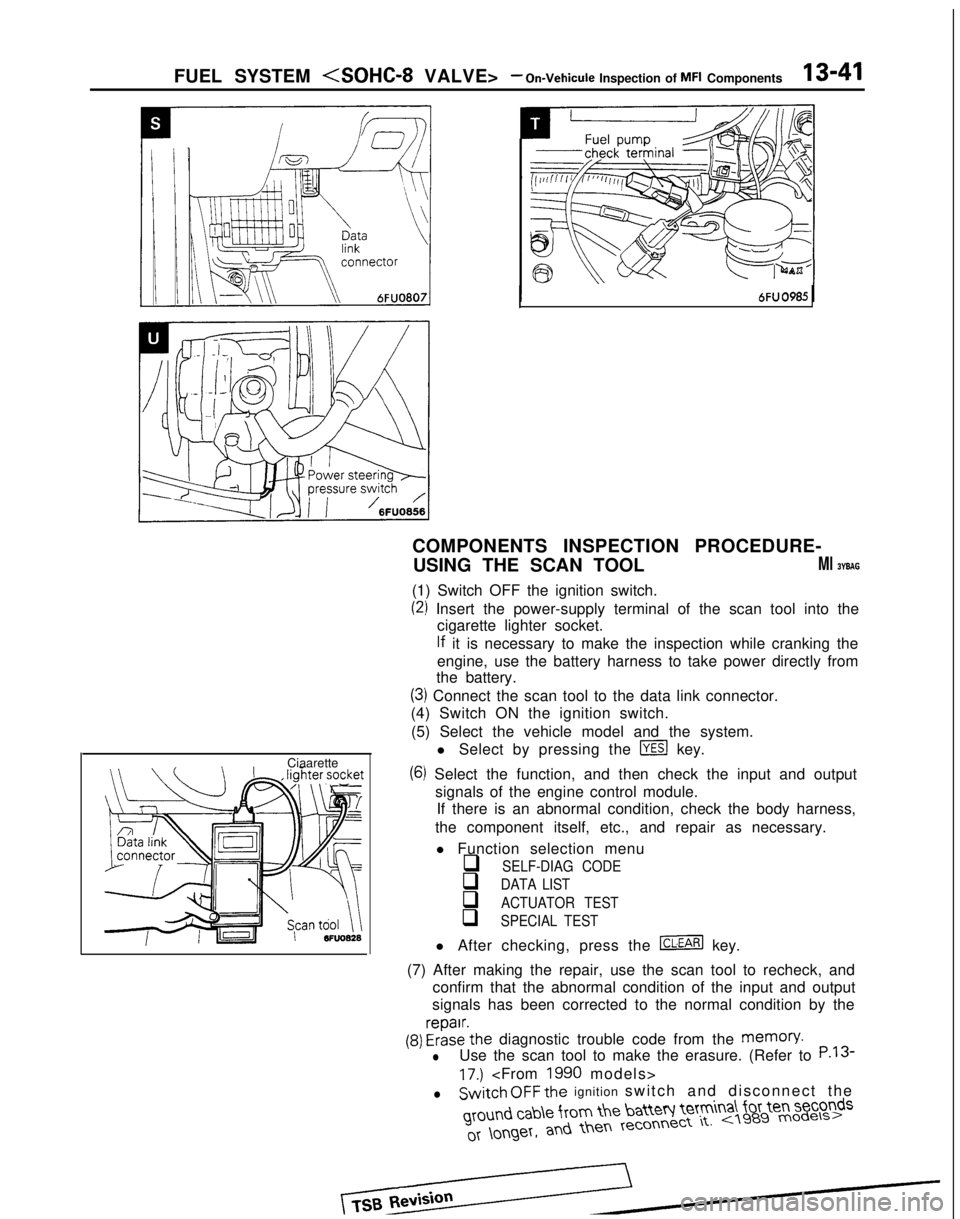
COMPONENTS INSPECTION PROCEDURE-
USING THE SCAN TOOL
Ml BYBAG
(1) Switch OFF the ignition switch.
(2) Insert the power-supply terminal of the scan tool into the cigarette lighter socket.
lf it is necessary to make the inspection while cranking the
engine, use the battery harness to take power directly from
the battery.
(3) Connect the scan tool to the data link connector.
(4) Switch ON the ignition switch.
(5) Select the vehicle model and the system. l Select by pressing the
m key.
(6) Select the function, and then check the input and outputsignals of the engine control module.If there is an abnormal condition, check the body harness,
the component itself, etc., and repair as necessary.
l Function selection menu
q SELF-DIAG CODE
q DATA LIST
q ACTUATOR TEST
q SPECIAL TEST
l After checking, press the m key.
(7) After making the repair, use the scan tool to recheck, and confirm that the abnormal condition of the input and output
signals has been corrected to the normal condition by the
(9) FrizE’the diagnostic trouble code from the memory.
lUse the scan tool to make the erasure. (Refer to P.13
17.)
lSwitch OFF the ignition switch and disconnect the ground
cab\e from the batteq Ie’tm
a\ for ten seconds
Page 263 of 1273
FUEL SYSTEM
ON-BOARD DIAGNOSTIC
The engine control module monitors the input/out- put signals (some signals at all times and the others
under specified conditions) of the engine control
module.
When it is noticed that an irregularity has continued
for a specified time or longer from when the irregu- lar signal is initially monitored, passing a certain
number, the engine control module judges that an irregularity has occurred, memorizes the diagnostic
trouble code, and outputs the signal to the on-board
diagnostic output terminal.
There are 15 on-board diagnostic items including
the normal state, and the diagnostic results can be read out with a voltmeter or scan tool.
Moreover, since memorization of the diagnostic
trouble codes is backed up directly by the battery,
the diagnostic results are memorized even if the ig- nition key is turned off. The diagnostic trouble
codes will, however, be erased when the battery
terminal or the engine control module connector is
disconnected. In addition, beginning with the engine
control module of
1990 and later models, the diag-
nostic trouble codes are erased by turning on the
ignition switch and sending the diagnostic trouble
code erase signal from the scan tool to the engine
DIAGNOSTIC CHART (FAULT TREE) control module.
Caution
If the sensor connector is disconnected with
the ignition switch turned on, the diagnostic
trouble code is memorized. In this case, send
the diagnostic trouble code erase signal from
the scan tool to the engine control module or
disconnect the battery terminal
(-) for 10 sec-
onds or more, and the diagnostic memory will
be erased.
The 15 on-board diagnostic items are provided as
follows, and if plural items are activated, they are all indicated sequentially from the smallest code num-
ber.
Caution
The diagnostic trouble code of ignition timing
adjustment signal is outputted when terminal
for ignition timing adjustment is short-cir- cuited. Therefore, it is not abnormal that the
code is outputted even when terminal for igni-
tion timing adjustment is short-circuited at the
time of ignition timing adjustment.
r
No.Output signal pattern
:i1zA0104
11
12
I3
:-J-l-J-12Ao104
Diagnostic trouble code-I
-
On-boarddiagnosticitem
Engine
control moduleCheck item (Remedy)IMemory
(Replace engine control module)-
Oxygensensorl Harness and connectorRetainedl Oxygen sensorl Fuel pressurel Injectors (Replace if defective.)l Intake air leaks
Volume air
l Harness and connectorRetainedflow sensor(If harness and connector are
normal, replace volume air flow
sensor assembly.)
Intake airl Harness and connector Retained
temperaturel Intake air temperature sensorsensor
TSB Revision
Page 348 of 1273
13-206FUEL SYSTEM
ON-BOARD DIAGNOSTIC
The engine control module monitors the input/out- put signals (some signals at all times and the others
under specified conditions) of the engine control
module.
When it is noticed that an irregularity has continued
for a specified time or longer from when the irregu- lar signal is initially monitored, passing a certain
number, the engine control module judges that an
irregularity has occurred, memorizes the diagnostic
trouble code, and outputs the signal to the on-board diagnostic output terminal.
There are 16 on-board diagnostic items, including
the normal state, and the diagnostic results can be read out with a voltmeter or scan tool.
Moreover, since memorization of the diagnostic
trouble codes is backed up directly by the battery,
the diagnostic results are memorized even if the ig- nition key is turned off. The diagnostic trouble
codes will, however, be erased when the battery
terminal or the engine control module connector is
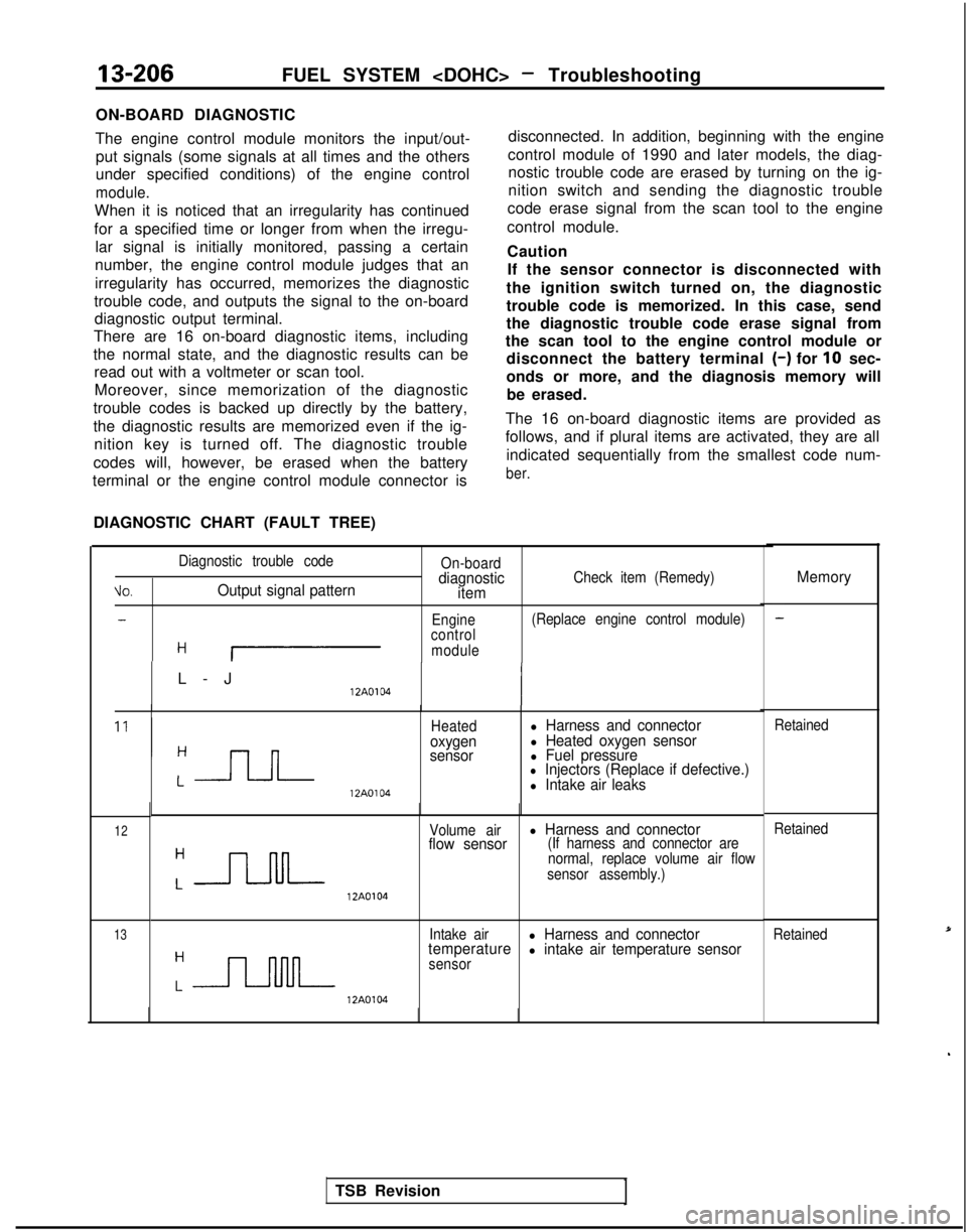
DIAGNOSTIC CHART (FAULT TREE) disconnected. In addition, beginning with the engine
control module of 1990 and later models, the diag- nostic trouble code are erased by turning on the ig-
nition switch and sending the diagnostic trouble
code erase signal from the scan tool to the engine
control module.
Caution If the sensor connector is disconnected with
the ignition switch turned on, the diagnostic
trouble code is memorized. In this case, send
the diagnostic trouble code erase signal from
the scan tool to the engine control module or disconnect the battery terminal
(-) for 10 sec-
onds or more, and the diagnosis memory will be erased.
The 16 on-board diagnostic items are provided as
follows, and if plural items are activated, they are all indicated sequentially from the smallest code num-
ber. ti0.
Diagnostic trouble code
Output signal pattern
On-boarddiagnostic
itemCheck item (Remedy)
-Engine (Replace engine control module)
control
H Imodule
L-
J
12A0104
Heatedoxygen
sensor
l Harness and connectorl Heated oxygen sensorl Fuel pressurel Injectors (Replace if defective.) 12A0104l Intake air leaks
12
13 12A0104Volume airl Harness and connector
flow sensor(If harness and connector are
normal, replace volume air flow
sensor assembly.)
Intake air
l Harness and connector
temperaturel intake air temperature sensorsensor 12A0104
Memory
Retained
Retained
Retained
TSB Revision
Page 547 of 1273

AUTO-CRUISE CONTROL SYSTEM - Sewice Adjustment Procedures
ECU connector terminals
19171513ll><7531
2018161412 101 98642
16A1060
ELECTRONIC CONTROL UNIT (ECU) SIGNAL CIRCUIT
CHECK
Disconnect the connector of the ECU, and then check at the
body side wiring harness according to the chart below.
IG SW: Ignition switch
MAIN SW: Main switch
OD SMI: Overdrive switch
Termi-~ Connection or mea-
nal
~
sured part Measure-
Tester con-
ment item nection
Check conditions
Standard
I-
I-
1 ~
Actuator (motor) Resistance1 - “‘2Actuator selector Approx. 120
(Fully closed position)
1
2
3I Stop light switchVoltage3-Ground ~
IG S/W ON, Main SW O
N
Battery positive
~
(for auto-cruise ~
control cancellation)
j )
i (Don’t press brake pedal.)j voltage
and actuator (clutch)I Press brake pedal after checkingBattery positive
5 1 Power supply (MAIN)
/ above.voltage -0V
Voltage5-Ground
1 IG S/W
ON, Main S/W ONBattery positive
voltage
6None-i -i-
7 1
Power supply (IGz)Voltag
e
7-GroundIG SfW O
N
Battery positive
voltage
8*z ~
On-board diagnostic--i- -
TSB Revision
9Accelerator pedal Voltageg-GroundIG SW O
N
Battery positive
switch
(Accelerator pedal free)voltage
1 Press accelerator pedal after/ Battery positive
II checking above.[voltage -0V
IO I Vehicle speed sensor
Voltage1 O-Ground’ W
ith the ignition key at the ON
’ ~
4 voltage
position, slowly turn the speedom- changes/
ca-
eter cable. ble
rotation
11SET switch
Continuity1 l-Ground ’ SET switch ON (Press) Continuity
SET switch OFF (Release) No continuity
12OD switch
13RESUME switch 1
Voltage
Continuity
12-GroundIG SNV ON OD SW ON position
Battery positive
voltage
OD
SW OFF position ~
OV
13-Ground ~
RESUME switch ON (Turn) Continuity
; RESUME switch OFF (Release)
No continuity
14’2 ~
4 A/T control module( -/- I- !
-
I/15 1 Stop light switch load
~
Voltage15-Ground’ Press the brake pedal.Battery positiveside/voltage
16 j Ground
Continuity1 16-GroundAt all times ~
Continuity
Page 733 of 1273
AUTOMATIC TRANSAXLE
- Troubleshootin
g
23-27
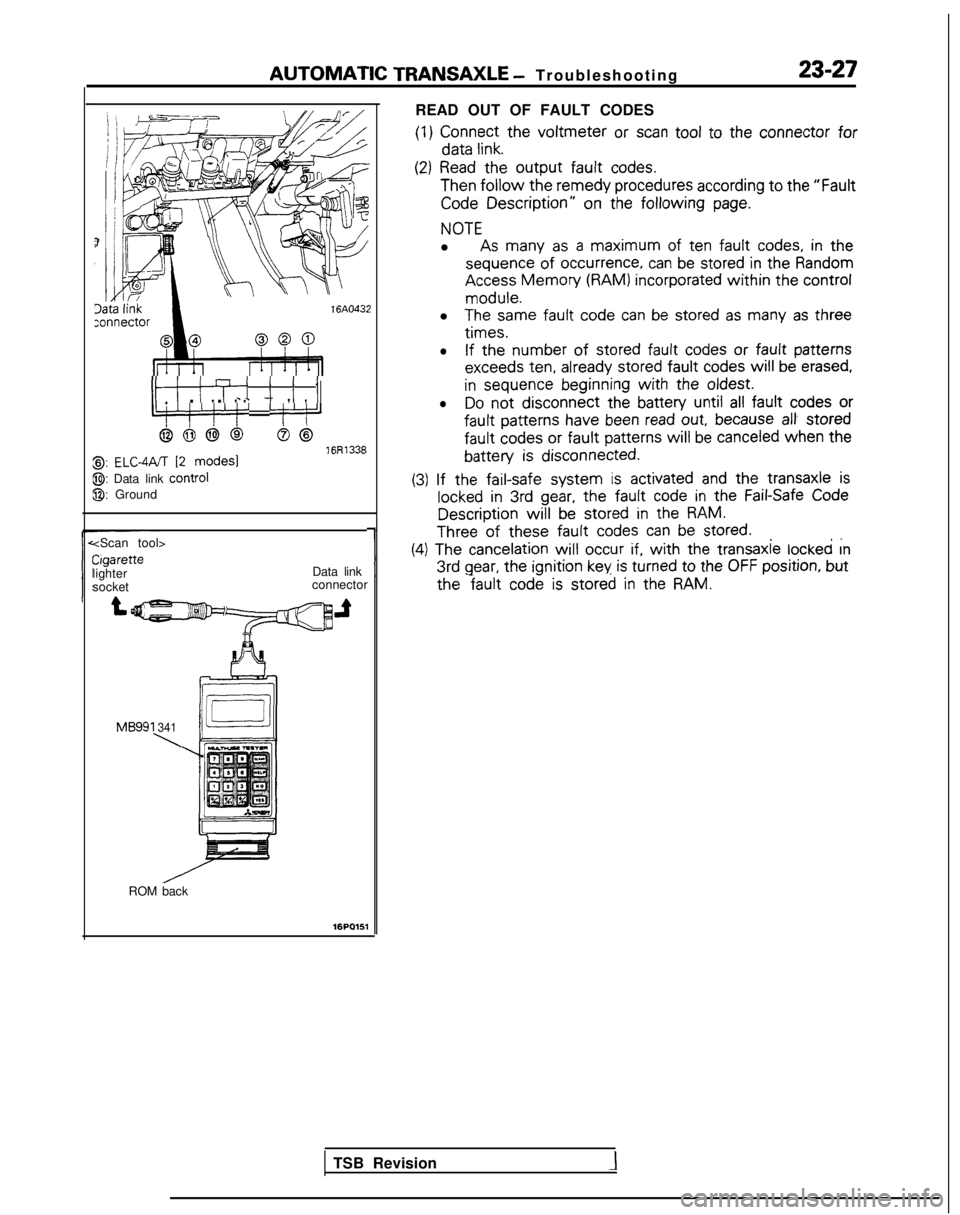
READ OUT OF FAULT CODES
(1)
Connect
the
voltmeter or scan tool
to the
connector
for data
link.
ItI ITi i i I_ . . c - 7 IIIL:‘!‘/‘!’ ‘j’:‘J
6666S@16R13388,: ELC-4PJT 12 modes1
@: Data link control
@: Ground
(2) Read
the
output fault
codes. Then
follow the remedy
procedures according to the
“Fault
Code Description”
on the following
page.
NOTE
l As many
as a maximum
of ten fault
codes, in the
sequence
of
occurrence,
can be stored
in the
Random Access
Memory (RAM) incorporated
within the
control
module.
l
The same
fault
code can be stored
as many
as three
times.
l
If the number
of stored
fault
codes or
fault
patterns
exceeds
ten,
already
stored
fault
codes
will be erased,
in
sequence
beginning
with the
oldest.
lDo
not
disconnect the
battery
until all fault
codes or
fault
patterns
have
been read out, because al! stored
fault
codes
or fault
patterns
will
be canceled when
the
battery is
disconnected.
~ ~~
(3)
If the
fail-safe
system is activated
and the
transaxle
is
locked in 3rd gear, the fault
code in the
Fail-Safe Code Description
will be stored
in the
RAM.
Three of these fault
codes can be stored.. ,.
Cigarette
lighter
socket
1
(4) The cancelation
will
occur if, with the
transaxle
locked rn 3rd
gear, the ignition
key is turned
to
the
OFF position,
but
Data link
connector the
fault code is stored
in the
RAM.
MB991 341
\
ROM back
16PO151
TSB Revision