Page 10 of 1273

00-8GENERAL - Vehicle Identification
VEHICLE IDENTIFICATIONMOOCA-
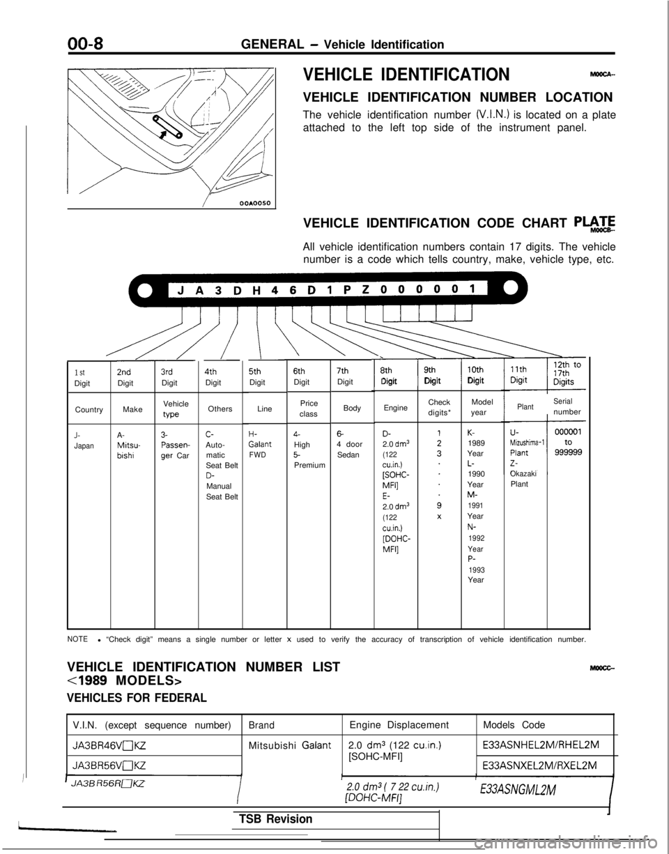
VEHICLE IDENTIFICATION NUMBER LOCATION
The vehicle identification number
(V.I.N.) is located on a plate
attached to the left top side of the instrument panel.
/ OOAOOSO
VEHICLE IDENTIFICATION CODE CHART
P+zE
All vehicle identification numbers contain 17 digits. The vehiclenumber is a code which tells country, make, vehicle type, etc.
\ \\L\.u 5th 6th 7th
r\ 8th 9th 10th
Digit DigitDigitDigit Digit
Digit
I
3rdDigit
/
4thDigit
/ 2nd
Digit
Line
H- Galant
FWD
1 StDigit
Body
6-4 doorSedan
Price
class4-High5-Premium Engine
Check
digits*Model
year
Make Vehicle
typeOthersPlantSerialnumber
Country
OkazakiPlant
D-2.0 dm3(122cu.in.)[SOHC- MFI]
E-2.0 dm3(122cu.in.)[DOHC-
MFI]
K-1989
Year
L-1990
Year
M-1991Year
N-
1992
Year
P-1993Year
J-JapanA- Mitsu-
bishr
3- Passen-
9er
Car c-
Auto- matic
Seat Belt
D-Manual
Seat Belt
NOTEl “Check digit” means a single number or letter x used to verify the accuracy of transcription of vehicle identification \
number.
VEHICLE IDENTIFICATION NUMBER LIST
Mlmcc-
VEHICLES FOR FEDERAL
V.I.N. (except sequence number)BrandEngine Displacement Models Code
JA3BR46VnKZMitsubishi Galant
2.0 dm3 (122 cu.in.) E33ASNHEL2M/RHEL2M
JA3BR56VaKZ[SOHC-MFI]
E33ASNXEL2MlFiXEL2M
JA3B R56RaKZ
/
2.0
dm3
( 7 22 cu.in.) [DOHC-MFI]E33ASNGMLZM
TSB Revision
Page 503 of 1273

AUTO-CRUISE CONTROL SYSTEM - Troubleshooting13-361
Wi
thscan tool
With voltmeter
Auto-cruise control
\
Data link
connector
III
n
,
/r-I
/Ground161009
Data link
connector
TSB Revision ON-BOARD DIAGNOSTIC CHECK
On-board diagnostic checking is performed when there has
been an automatic cancellation, without cancel switch opera-
tion.
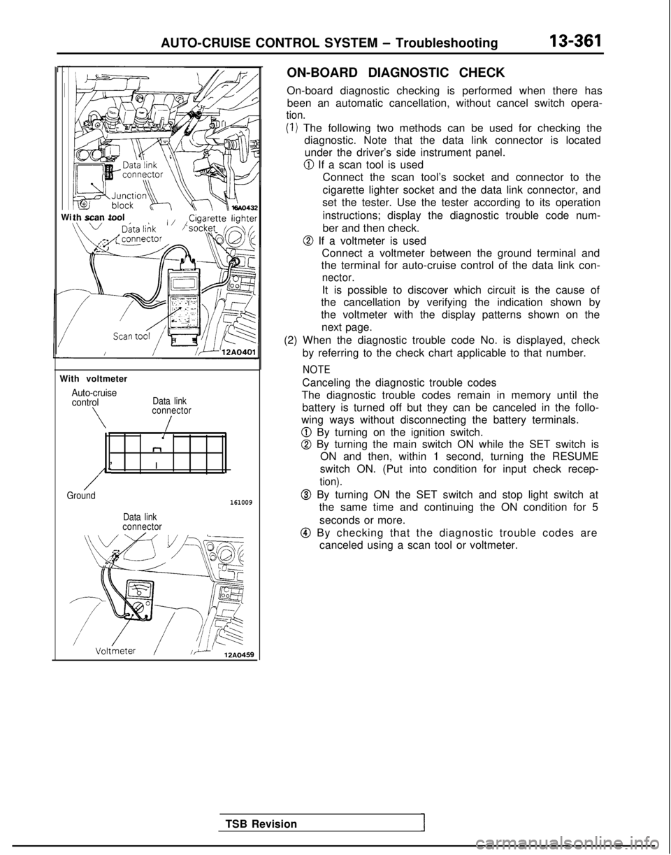
(1) The following two methods can be used for checking the diagnostic. Note that the data link connector is locatedunder the driver’s side instrument panel.
@ If a scan tool is used
Connect the scan tool’s socket and connector to the
cigarette lighter socket and the data link connector, and
set the tester. Use the tester according to its operation
instructions; display the diagnostic trouble code num-
ber and then check.
@ If a voltmeter is used Connect a voltmeter between the ground terminal and
the terminal for auto-cruise control of the data link con-
nector.
It is possible to discover which circuit is the cause of
the cancellation by verifying the indication shown by
the voltmeter with the display patterns shown on the
next page.
(2) When the diagnostic trouble code No. is displayed, check by referring to the check chart applicable to that number.
NOTE
Canceling the diagnostic trouble codes
The diagnostic trouble codes remain in memory until the battery is turned off but they can be canceled in the follo-
wing ways without disconnecting the battery terminals.
@ By turning on the ignition switch.
@ By turning the main switch ON while the SET switch is ON and then, within 1 second, turning the RESUME
switch ON. (Put into condition for input check recep-
tion).
@ By turning ON the SET switch and stop light switch at the same time and continuing the ON condition for 5
seconds or more.
@I By checking that the diagnostic trouble codes are canceled using a scan tool or voltmeter.
Page 509 of 1273
AUTO-CRUISE CONTROL SYSTEM - Troubleshootinn13-367
LOCATION OF CONTROL UNIT
w
16AO406
GROUND POINT
JUNCTION BLOCK p-;a
Front
harness
t
Instrument
Roof
harnessr’ II
Ji
-I
$!&;Ipanel
harness Body
harness
z$gger ~----#$jfiillITiHeater- relav
7
J
fuses)
16A0002m36I
TSB Revision
Page 657 of 1273
CLUTCH - Clutch Pedalm-7
CLUTCH PEDAL
REMOVAL AND INSTALLATION
Pre-removal and Post-installation Operation*Removal and Installation of InstrumentUnder Cover
(Refer to GROUP 52-Instrument Panel.)l Removal and Installation of Steering Col-umn Assembly (Refer to GROUP 37A-Steering Wheel and Shaft.)
Adjustmentl Adjustment of Brake Pedal (Refer tcGROUP 35-Service Adjustment Procedures.)@Adjustment of Clutch Pedal
(Refer to P.21-5.)
MZIPA-
2
8-12 Nm
6-9 ft.lbs.
r:-20-25Nmi12Lib-18ft.lbs.*21lo-15 Nm -7-11 ftlbs.
23
24
09AOO79
Semoval steps
1. Return spring
2. Interlock switch
3. Clutch pedal position switch
with auto-cruise control system>
4. Bolt
system>
12. Cotter pin
13. Washer
14. Clevis pin
15. Clutch pedal bracket
16. Pedal suppon bracket
17. Nut
18. Lever
19.Bushing (small)20. Pedal rod
21.
22. Bushing (large)
Clutch pedal23.
Brake pedal
24. Pedal pad
NOTEl ‘: 1989 modelsl *: From 1990 models
TSB Revision
Page 658 of 1273
21-8CLUTCH- Clutch Pedal
Pre-removal and Post-installation Op-eration*Removal and Installation of instrumentUnder Cover
(Refer to GROUP 52-Instrument Panel.)*Removal and Installation of Steering Col-
umn Assembly (Refer to GROUP 37A-
Steering Wheel and Shaft.)
Adjustmentl Adjustment of Brake Pedal (Refer to
GROUP 35-Service Adjustment Proce-dures.)*Adjustment of Clutch Pedal
(Refer to P.21-5.1
3
22
“,24 00AOO82
Removal steps
I. Return spring 14. Clevis pin15. @fch pedal bracket2.Interlock switch3. Clutch pedal position switcn5.Cotter pin6.Washer7.Bushing;: E;;i; pin
;
;: poTrer spring
12.Cotter pin13.Washer 16. Pedal support bracket
17.Nut18.Lever19.Bushing (small)20.Pedal rod21.Bushing (large)22.Clutch pedal23.Brake pedal24.
Pedal pad
TSB Revision
Page 669 of 1273
MANUAL TRANSAXLE - Service Adjustment Procedures27-5
Adapter09A0058
TSB Revision
SPEEDOMETER CABLE REPLACEMENT~~FEIE
1.Correctly insert the adapter into the instrument panel, and
fasten the new speedometer cable.
2.Install the grommet so that, as shown in the illustration, the’
cable attachment part is positioned upward.
Caution 1. The cable arrangement should be made so that the
radius of cable bends is 150 mm (5.9 in.) or more.
2. The arrangement of the speedometer cable should be such that it does not interfere with brake tubes,
etc.
3. At the transaxle end of the speedometer cable, the key
joint should be inserted into the transaxle, and the nutshould be securely tightened.
Caution
If the cable is not correctly and securely connected, it
may cause incorrect indication by the speedometer, or
abnormal noise. Be sure to connect it correctly.
Page 799 of 1273

AUTOMATIC TRANSAXLE - Service Adjustment Procedures23-93
MD998325-01
160024
-
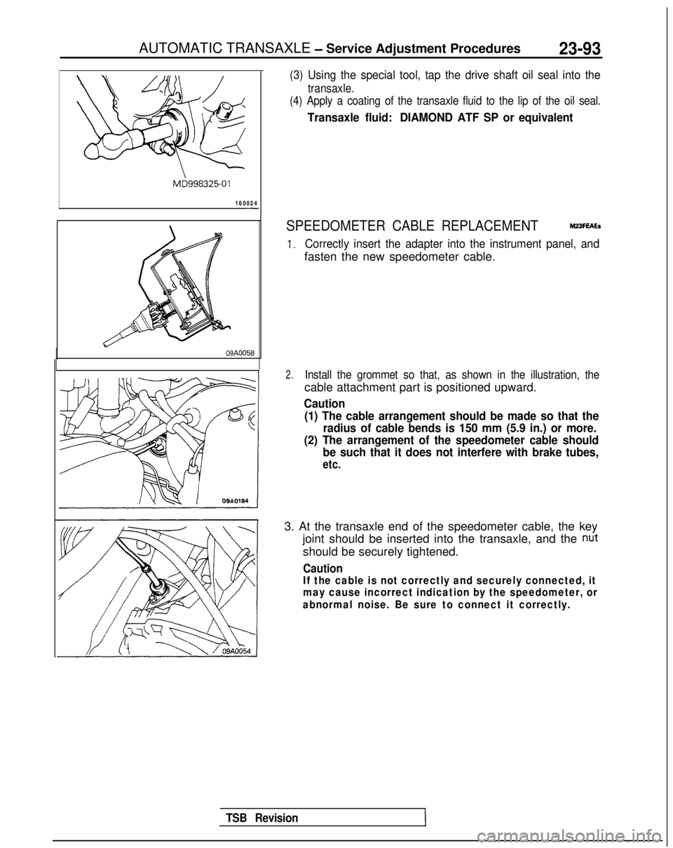
(3) Using the special tool, tap the drive shaft oil seal into the
transaxle.
(4) Apply a coating of the transaxle fluid to the lip of the oil seal.\
Transaxle fluid: DIAMOND ATF SP or equivalent
SPEEDOMETER CABLE REPLACEMENTMUFEAEa
1.Correctly insert the adapter into the instrument panel, and
fasten the new speedometer cable.
TSB Revision
2.Install the grommet so that, as shown in the illustration, the
cable attachment part is positioned upward.
Caution
(1) The cable arrangement should be made so that the radius of cable bends is 150 mm (5.9 in.) or more.
(2) The arrangement of the speedometer cable should be such that it does not interfere with brake tubes,
etc.
3. At the transaxle end of the speedometer cable, the key
joint should be inserted into the transaxle, and the
nut
should be securely tightened.
Caution
If the cable is not correctly and securely connected, it
may cause incorrect indication by the speedometer, or
abnormal noise. Be sure to connect it correctly.
Page 801 of 1273
AUTOMATIC TRANSAXLE - Transaxle Control23-95
4-6‘Nm3-4 ftlbs.
Pre-removal and Post-installation Operation*Removal and Installation of Console Box Assembly(Refer to GROUP 52-Floor Console.)@Removal and Installation of Instrument Under Cover Assem-
s;bly, Column Cover, Lap Shower Duct and Foot Shower
(Refer to GROUP 5’2-Instrument
Panel.)
9-14 Nm7-10 ftlbs.
4-6 Nm
3-4 ftlbs.
09A0138
Key-interlock cable removal steps
1. Snap pinl +2. Key-interlock cable (selector lever
assembly side)
3. Clamp
4. Cover
I)* 5. Key-interlock cable (steering lock assembly side)
I)+ 6. Slide lever
NOTEBefore connecting the key-interlock cable or the shift-lock
cable, be sure to first connect and adjust the transaxle Shift-lock
cable removal steps
3. Clam
I)+ 7
.
Shift- ock cable
P(selector lever assembly side)
8. Coffer pin
9. Shift-lock cable (brake pdeal side)
control cable.
TSB Revision