Page 23 of 1273

GENERAL - Special Handling Instructions for AWD Models00-21
Free roller
OOPO038
Axle stand
OOPOO37
Towino hook
Tenslon
bar
Front
eJ
Anchor plate
&-16PO209 14AO198
OOP003E
SPEEDOMETER TEST
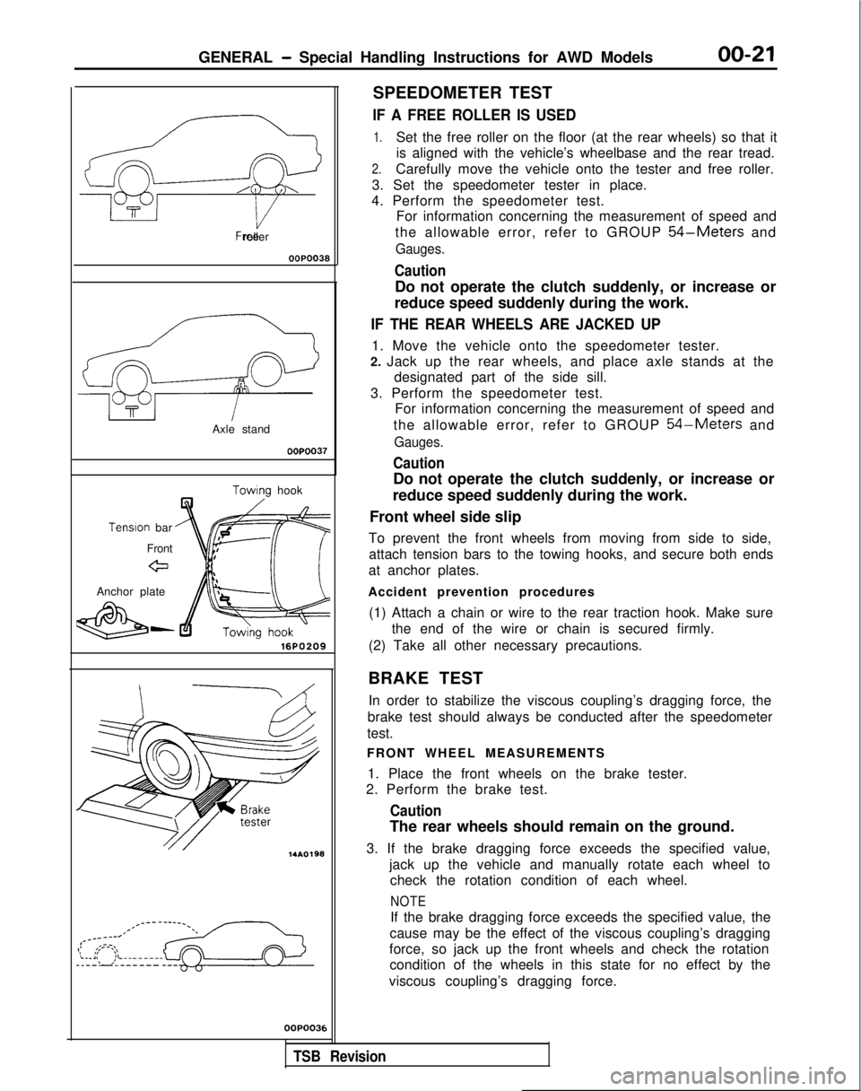
IF A FREE ROLLER IS USED
1.Set the free roller on the floor (at the rear wheels) so that it
is aligned with the vehicle’s wheelbase and the rear tread.
2.Carefully move the vehicle onto the tester and free roller.
3. Set the speedometer tester in place.
4. Perform the speedometer test. For information concerning the measurement of speed and
the allowable error, refer to GROUP
54-Meters and
Gauges.
Caution
Do not operate the clutch suddenly, or increase or
reduce speed suddenly during the work.
IF THE REAR WHEELS ARE JACKED UP
1. Move the vehicle onto the speedometer tester.
2. Jack up the rear wheels, and place axle stands at the designated part of the side sill.
3. Perform the speedometer test. For information concerning the measurement of speed and
the allowable error, refer to GROUP
54-Meters and
Gauges.
Caution
Do not operate the clutch suddenly, or increase or
reduce speed suddenly during the work.
Front wheel side slip
To prevent the front wheels from moving from side to side, attach tension bars to the towing hooks, and secure both ends
at anchor plates.
Accident prevention procedures (1) Attach a chain or wire to the rear traction hook. Make sure the end of the wire or chain is secured firmly.
(2) Take all other necessary precautions.
BRAKE TEST In order to stabilize the viscous coupling’s dragging force, the
brake test should always be conducted after the speedometer
test.
FRONT WHEEL MEASUREMENTS
1. Place the front wheels on the brake tester.
2. Perform the brake test.
Caution
The rear wheels should remain on the ground.
3. If the brake dragging force exceeds the specified value, jack up the vehicle and manually rotate each wheel tocheck the rotation condition of each wheel.
NOTE
If the brake dragging force exceeds the specified value, the
cause may be the effect of the viscous coupling’s dragging
force, so jack up the front wheels and check the rotation condition of the wheels in this state for no effect by the
viscous coupling’s dragging force.
,
TSB Revision
Page 810 of 1273

23-104AUTOMATIC TRANSAXLE - Transaxle Assembly 4WD>
OPTIONAL12K513
Pry baraTransaxle
llKf311I
SERVICE POINTS OF REMOVALM23LBAK
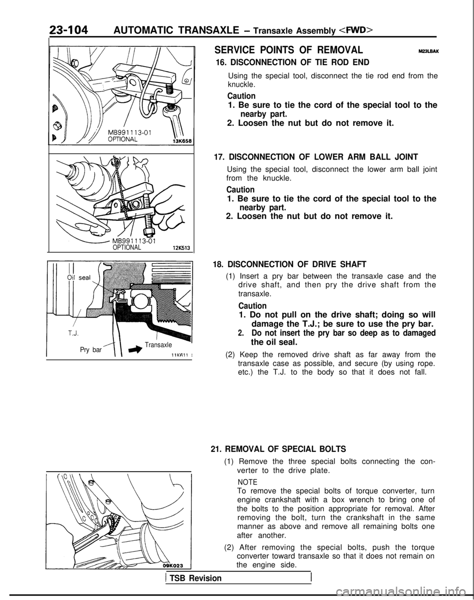
16. DISCONNECTION OF TIE ROD END
Using the special tool, disconnect the tie rod end from the
knuckle.
Caution
1. Be sure to tie the cord of the special tool to the
nearby part.
2. Loosen the nut but do not remove it.
17. DISCONNECTION OF LOWER ARM BALL JOINT
Using the special tool, disconnect the lower arm ball joint
from the knuckle.
Caution
1. Be sure to tie the cord of the special tool to the
nearby part.
2. Loosen the nut but do not remove it.
18. DISCONNECTION OF DRIVE SHAFT
(1) Insert a pry bar between the transaxle case and the drive shaft, and then pry the drive shaft from the
transaxle.
Caution
1. Do not pull on the drive shaft; doing so will
damage the T.J.; be sure to use the pry bar.
2.Do not insert the pry bar so deep as to damaged
the oil seal.
(2) Keep the removed drive shaft as far away from the transaxle case as possible, and secure (by using rope.
etc.) the T.J. to the body so that it does not fall.
21. REMOVAL OF SPECIAL BOLTS
(1) Remove the three special bolts connecting the con-
verter to the drive plate.
NOTE
To remove the special bolts of torque converter, turnengine crankshaft with a box wrench to bring one of
the bolts to the position appropriate for removal. After removing the bolt, turn the crankshaft in the same
manner as above and remove all remaining bolts one
after another.
(2) After removing the special bolts, push the torque converter toward transaxle so that it does not remain on
the engine side.
1 TSB Revision
Page 1046 of 1273
ACTIVE-ELECTRONIC CONTROL SUSPENSION - Stabilizer Bar33Bl107
UL Wire/
12A0283SERVICE POINTS OF REMOVAL
2. REMOVAL OF FRONT EXHAUST PIPE
After disconnection of the front exhaust pipe assembly and
the exhaust manifold, use wire, etc. to hang the front
exhaust pipe down.
Caution Do not bend the flexible joint more than shown in the
figure, because there is danger the inside may be
damaged if it is bent too much.
7. REMOVAL OF STABILIZER LINK MOUNTING NUTS Using a wrench or similar tool to secure the ball studs at
both ends of the stabilizer link, remove the mounting nuts.
12. REMOVAL OF STABILIZER
BAR
(1) Disconnect either the left or right lower arm from the crossmember, and slightly lower the installation part.
(2) Pull out both ends of the stabilizer bar to the rear of the drive shaft.
NOTE
First pass the end of the stabilizer bar (at the side at
which the lower arm was not lowered) under the drive shaft, and then pull out toward the rear.
Page 1108 of 1273

REAR SUSPENSION - Rear Suspension Assembly34-27
12A0222
12A.0221
,
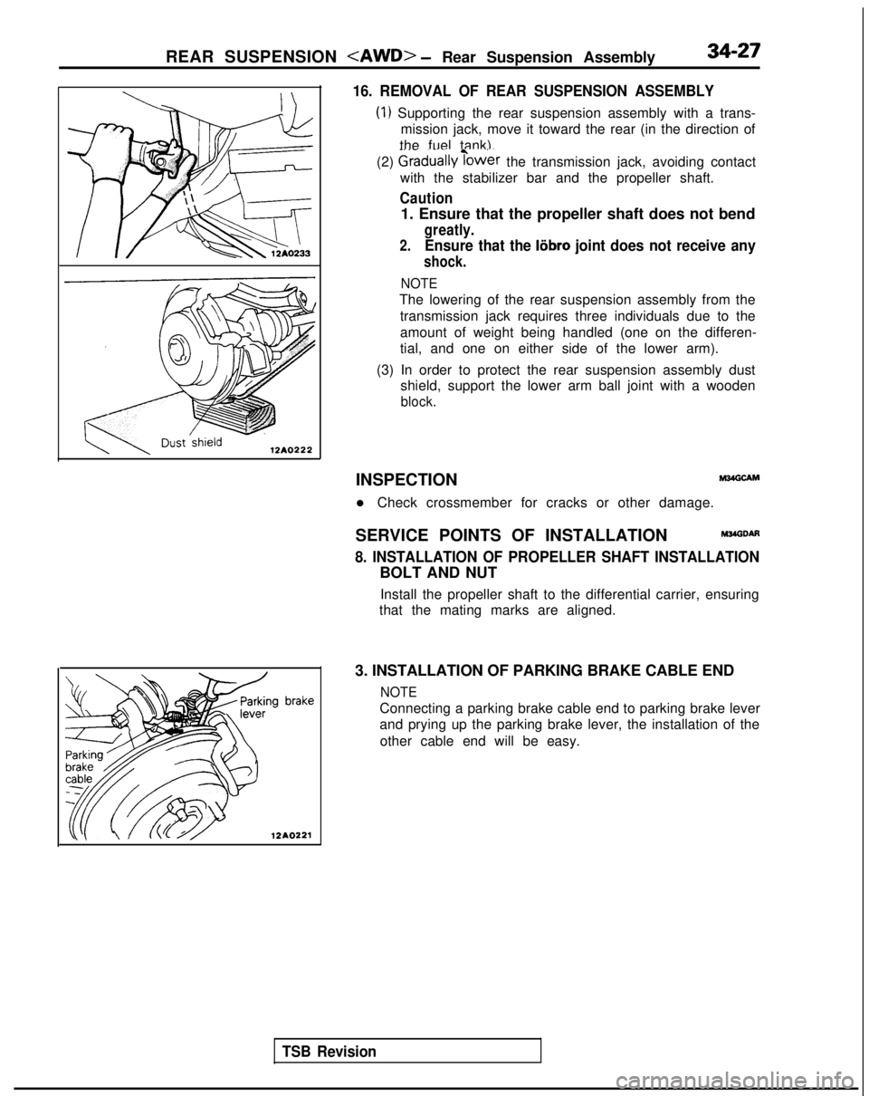
16. REMOVAL OF REAR SUSPENSION ASSEMBLY
(1) Supporting the rear suspension assembly with a trans-
mission jack, move it toward the rear (in the direction of
the fuel tank).
(2)
Graduallyibwer the transmission jack, avoiding contact
with the stabilizer bar and the propeller shaft.
Caution
1. Ensure that the propeller shaft does not bend
greatly.
2.Ensure that the liibro joint does not receive any
shock.
NOTE
The lowering of the rear suspension assembly from the
transmission jack requires three individuals due to the
amount of weight being handled (one on the differen-
tial, and one on either side of the lower arm).
(3) In order to protect the rear suspension assembly dust shield, support the lower arm ball joint with a wooden
block.
TSB Revision
INSPECTIONM24GCAM
l Check crossmember for cracks or other damage.
SERVICE POINTS OF INSTALLATION
M34GDAfl
8. INSTALLATION OF PROPELLER SHAFT INSTALLATION
BOLT AND NUT Install the propeller shaft to the differential carrier, ensuring
that the mating marks are aligned.
3. INSTALLATION OF PARKING BRAKE CABLE END
NOTE
Connecting a parking brake cable end to parking brake lever
and prying up the parking brake lever, the installation of the other cable end will be easy.