1989 MITSUBISHI GALANT belt
[x] Cancel search: beltPage 3 of 1273
00-l
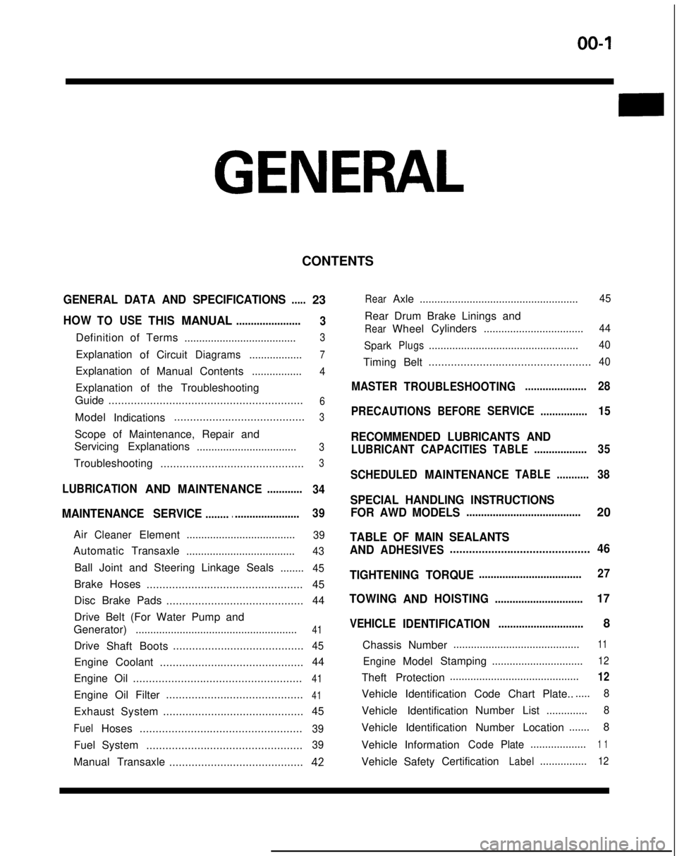
GENERAL
CONTENTS
GENERAL DATA AND SPECIFICATIONS.....23
HOWTOUSETHISMANUAL......................
3
Definition of Terms ......................................3
ExplanationofCircuitDiagrams..................7
Explanation of
ManualContents .................4
Explanation of the Troubleshooting
Guide .............................................................
6
Model
Indications .........................................3
Scope of Maintenance, Repair and
Servicing Explanations
..................................
3
Troubleshooting .............................................3
LUBRICATIONANDMAINTENANCE............
34
MAINTENANCE SERVICE............................... 39
AirCleanerElement
.....................................39
Automatic
Transaxle
.....................................43
Ball Joint and Steering Linkage Seals ........45
Brake Hoses................................................. 45
Disc Brake Pads ........................................... 44
Drive Belt (For Water Pump and
Generator) .......................................................
41
Drive
Shaft Boots .........................................45
Engine Coolant
............................................. 44
Engine Oil .....................................................
41
Engine Oil Filter ...........................................41
Exhaust System
............................................ 45
FuelHoses
...................................................39
Fuel System
.................................................39
Manual Transaxle ..........................................42
RearAxle......................................................45
Rear Drum Brake Linings and
RearWheel Cylinders
..................................44
Spark
Plugs...................................................40
Timing Belt...................................................40
MASTER
TROUBLESHOOTING.....................28
PRECAUTIONS
BEFORESERVICE................15
RECOMMENDED LUBRICANTS AND
LUBRICANT CAPACITIESTABLE..................35
SCHEDULED
MAINTENANCETABLE ...........38
SPECIAL HANDLING INSTRUCTIONS
FOR AWD MODELS
.......................................20
TABLE OF MAIN SEALANTS
AND
ADHESIVES ............................................46
TIGHTENING TORQUE
................................... 27
TOWING
ANDHOISTING ..............................17
VEHICLE
IDENTIFICATION .............................8
Chassis Number ...........................................
11
EngineModel
Stamping
...............................12
Theft Protection ............................................12
Vehicle Identification Code Chart Plate.......
8
Vehicle Identification Number List
..............8
Vehicle Identification Number Location .......
8
Vehicle Information
CodePlate...................1 1
Vehicle SafetyCertificationLabel................12
Page 10 of 1273
00-8GENERAL - Vehicle Identification
VEHICLE IDENTIFICATIONMOOCA-
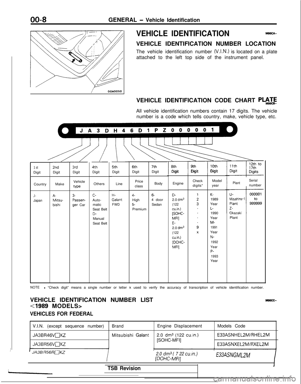
VEHICLE IDENTIFICATION NUMBER LOCATION
The vehicle identification number
(V.I.N.) is located on a plate
attached to the left top side of the instrument panel.
/ OOAOOSO
VEHICLE IDENTIFICATION CODE CHART
P+zE
All vehicle identification numbers contain 17 digits. The vehiclenumber is a code which tells country, make, vehicle type, etc.
\ \\L\.u 5th 6th 7th
r\ 8th 9th 10th
Digit DigitDigitDigit Digit
Digit
I
3rdDigit
/
4thDigit
/ 2nd
Digit
Line
H- Galant
FWD
1 StDigit
Body
6-4 doorSedan
Price
class4-High5-Premium Engine
Check
digits*Model
year
Make Vehicle
typeOthersPlantSerialnumber
Country
OkazakiPlant
D-2.0 dm3(122cu.in.)[SOHC- MFI]
E-2.0 dm3(122cu.in.)[DOHC-
MFI]
K-1989
Year
L-1990
Year
M-1991Year
N-
1992
Year
P-1993Year
J-JapanA- Mitsu-
bishr
3- Passen-
9er
Car c-
Auto- matic
Seat Belt
D-Manual
Seat Belt
NOTEl “Check digit” means a single number or letter x used to verify the accuracy of transcription of vehicle identification \
number.
VEHICLE IDENTIFICATION NUMBER LIST
Mlmcc-
VEHICLES FOR FEDERAL
V.I.N. (except sequence number)BrandEngine Displacement Models Code
JA3BR46VnKZMitsubishi Galant
2.0 dm3 (122 cu.in.) E33ASNHEL2M/RHEL2M
JA3BR56VaKZ[SOHC-MFI]
E33ASNXEL2MlFiXEL2M
JA3B R56RaKZ
/
2.0
dm3
( 7 22 cu.in.) [DOHC-MFI]E33ASNGMLZM
TSB Revision
Page 32 of 1273
00-30GENERAL - Master Troubleshooting
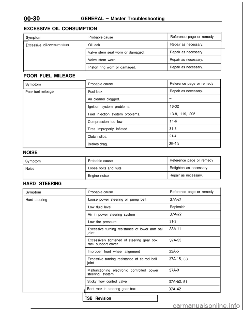
EXCESSIVE OIL CONSUMPTION Symptom Probable cause Reference page or remedy
1
r-Excessive 011 consumption
Oil leak Repair as necessary.I Valve
stem seal worn or damaged. Repair as necessary.
Valve stem worn. Repair as necessary.
Piston ring worn or damaged. Repair as necessary.
POOR FUEL MILEAGE Symptom
Poor fuel mtleage
Probable cause
Fuel leak
Air cleaner clogged. Ignition system problems.
Fuel injection system problems.
Compression too low.
Tires improperly inflated.
Clutch slips.Brakes drag. Reference page or remedy
Repair as necessary.
-
16-32
13-8, 119, 205
1 l-6
31-3 21-4
35-l 3
NOISE
SymptomNoise Probable cause
Loose bolts and nuts.
Engine noise Reference page or remedy
Retighten as necessary.
Repair as necessary.
HARD STEERING
Symptom
Hard steering Probable cause
Reference page or remedy
Loose power steering oil pump belt
37A-21
Low fluid level Replenish
Air in power steering system
37A-22
Low tire pressure31-3
Excessive turning resistance of lower arm ball33A-11
joint Excessively tightened of steering gear box 37A-33
rack support cover
Improper front wheel alignment
Excessive turning resistance of tie-rod ball
joint
Malfunctioning electronic controlled power
steering system
Sticky flow control valve
Bent rack in steering gear box
J
TSB RevisionI
33A-5
37A-15, 33 37A-9
37A-50,
51 37A-42
Page 40 of 1273
00-38GENERAL- Scheduled Maintenance Table
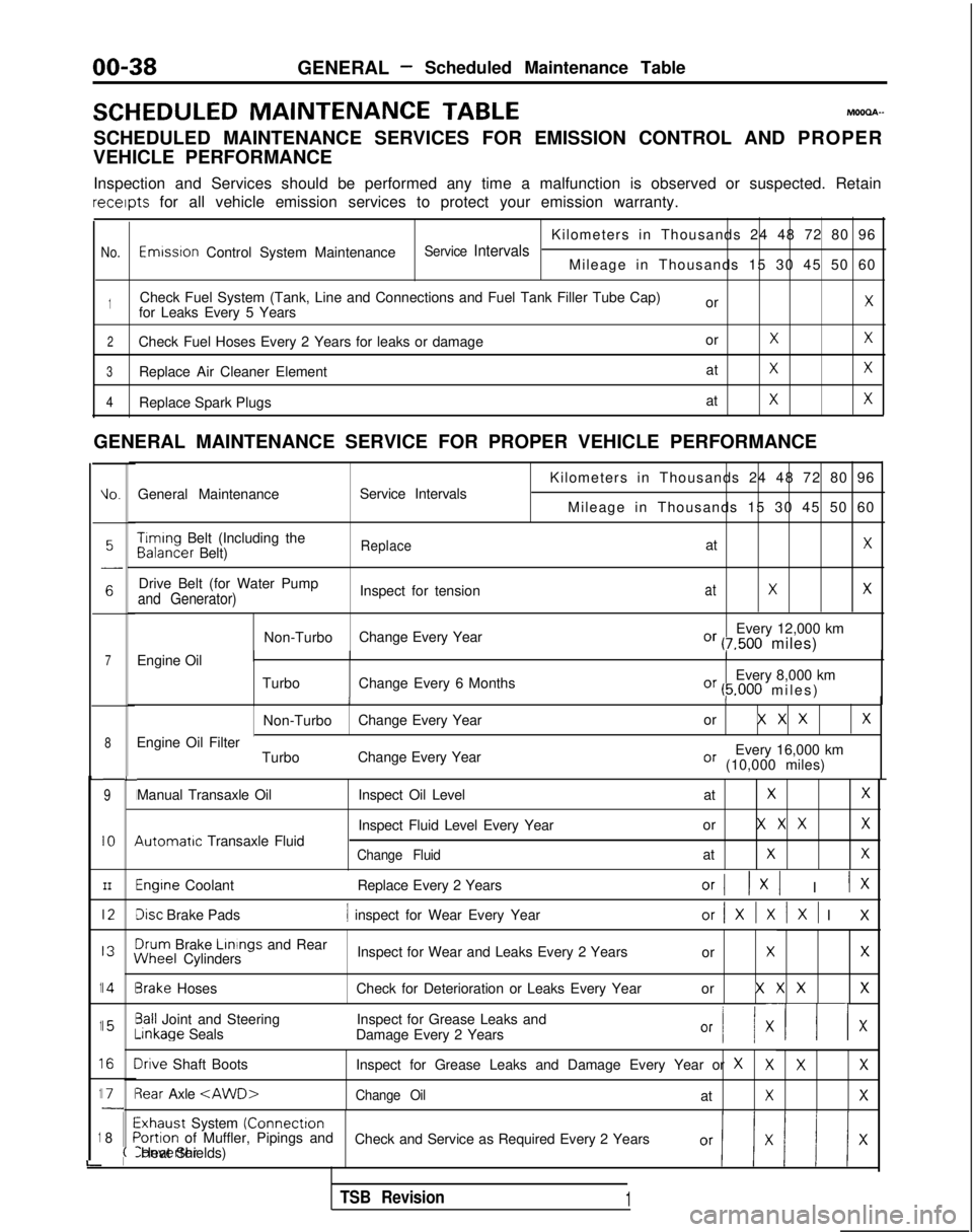
SCHEDULED MAINTENANCE
TABLEMOOOA-
SCHEDULED MAINTENANCE SERVICES FOR EMISSION CONTROL AND PROPER
VEHICLE PERFORMANCE
Inspection and Services should be performed any time a malfunction is ob\
served or suspected. Retain receipts
for all vehicle emission services to protect your emission warranty.
Kilometers in Thousands 24 48 72 80 96
No.Emwsron Control System MaintenanceService IntervalsMileage in Thousands 15 30 45 50 60
1Check Fuel System (Tank, Line and Connections and Fuel Tank Filler Tube\
Cap) orXfor Leaks Every 5 Years
2Check Fuel Hoses Every 2 Years for leaks or damage orXX
3Replace Air Cleaner ElementatXX
4Replace Spark PlugsatXX
GENERAL MAINTENANCE SERVICE FOR PROPER VEHICLE PERFORMANCE
L
1
1
1
1
1
i
IO.General Maintenance
Service Intervals
7Engine Oil
8
9
IO
III2
I3
14
15
I6
I71
8
L
I
I
I
I
I\
I
II
I
I
;(
Kilometers in Thousands 24 48 72 80 96
Mileage in Thousands 15 30 45 50 60 Timing
Belt (Including the Balancer
Belt)
ReplaceatX
Drive Belt (for Water Pump
Inspect for tensionatXXand Generator)
Non-TurboChange Every Year Every 12,000 kmOr (7,500 miles)
Turbo Change Every 6 Months Every 8,000 km
Or (5.000 miles
)
II
Non-Turbo
Change Every Year or X X XX
Every 16,000 kmOr (10,000 miles)
Engine Oil Filter
TurboChange Every Year
Manual Transaxle Oil 4utomatrc
Transaxle Fluid Inspect Oil Level
at
XX
Inspect Fluid Level Every Yearor X X XX
Change FluidatXX
Engine Coolant
Replace Every 2 YearsOrI 1x1 I IX
Disc Brake Pads1 inspect for Wear Every Yearor/XlXlXl I
X
3rum
Brake Linings
and Rear iNheel
Cylinders Inspect for Wear and Leaks Every 2 Years
or
XX
3rake HosesCheck for Deterioration or Leaks Every Year or X X XX
3all Joint and SteeringInspect for Grease Leaks and-inkage
Seals
Damage Every 2 Years
Or I/ XII x
Irive Shaft Boots Inspect for Grease Leaks and Damage Every Year or XXXX
3ear Axle
Exhaust System (Connectron>ortion of Muffler, Pipings and
Check and Service as Required Every 2 YearsConverter Heat Shields)
TSB Revision1
Page 42 of 1273
00-40GENERAL- Maintenance Service
Caution
The air cleaner cover should be removed carefully,
because it includes the volume air flow sensor.
/
(5) Remove the air cleaner element.(6) Set a new air cleaner element and install the air cleaner cover.
I hose,I
Plug gapgauge
Measurementrection01
If
0110182
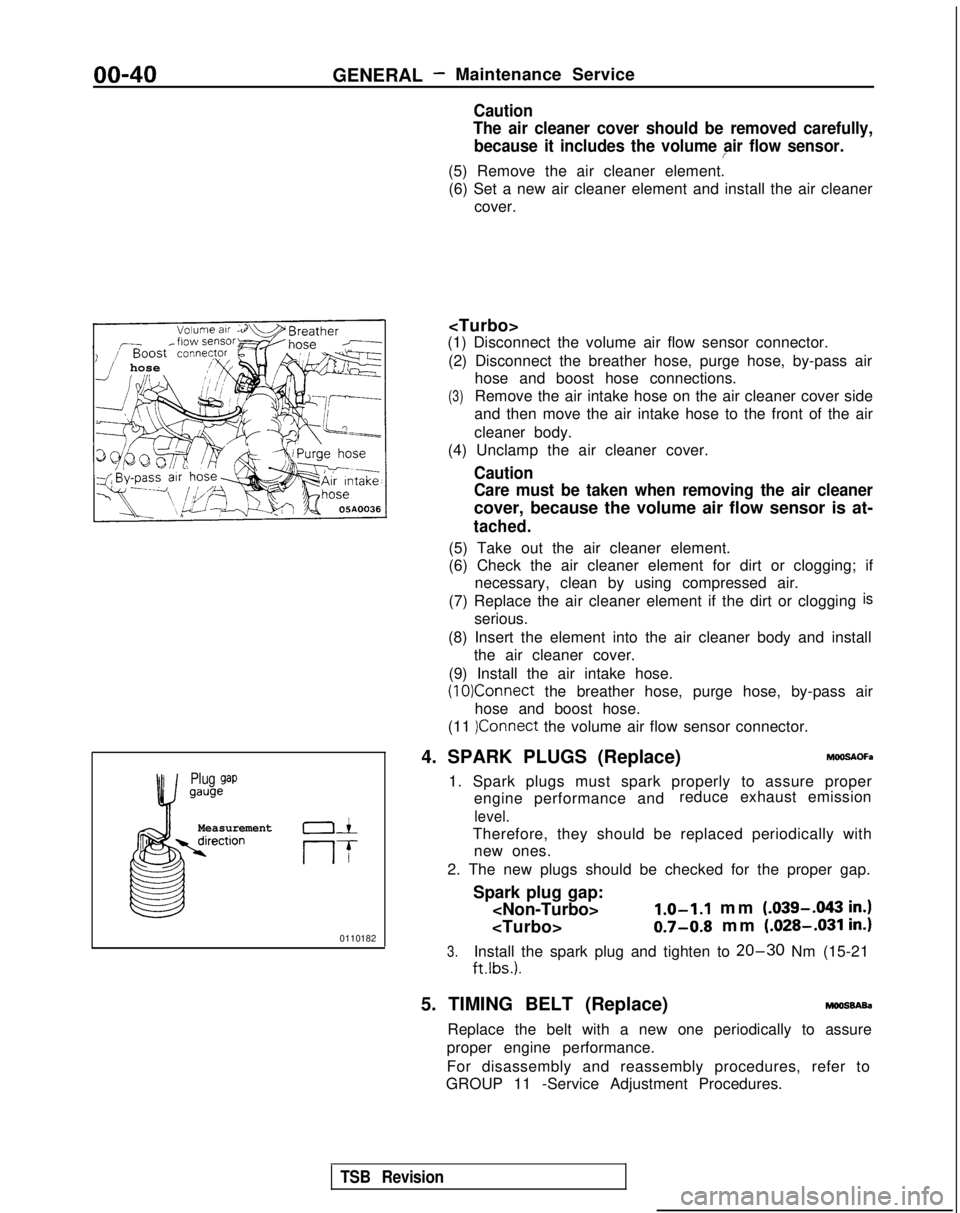
(1) Disconnect the volume air flow sensor connector.
(2) Disconnect the breather hose, purge hose, by-pass air hose and boost hose connections.
(3)Remove the air intake hose on the air cleaner cover side
and then move the air intake hose to the front of the air
cleaner body.
(4) Unclamp the air cleaner cover.
Caution
Care must be taken when removing the air cleaner
cover, because the volume air flow sensor is at-
tached.
(5) Take out the air cleaner element.
(6) Check the air cleaner element for dirt or clogging; if necessary, clean by using compressed air.
(7) Replace the air cleaner element if the dirt or clogging
is
serious.
(8) Insert the element into the air cleaner body and install the air cleaner cover.
(9) Install the air intake hose.
(10)Connect the breather hose, purge hose, by-pass air
hose and boost hose.
(11
)Connect the volume air flow sensor connector.
4. SPARK PLUGS (Replace)
h%OSAOFa
1. Spark plugs must spark properly to assure proper engine performance and reduce exhaust emission
level.
Therefore, they should be replaced periodically with
new ones.
2. The new plugs should be checked for the proper gap.
Spark plug gap:
mm (.039-.043
in.)
0.7-0.8 mm (.028-.031 in.)
3.Install the spark plug and tighten to 20-30 Nm (15-21
ftlbs.).
5. TIMING BELT (Replace)moossAsa
Replace the belt with a new one periodically to assure
proper engine performance.
For disassembly and reassembly procedures, refer to
GROUP 11 -Service Adjustment Procedures.
TSB Revision
Page 43 of 1273
GENERAL - Maintenance Service00-41
-1
6COOO9
L!6COO39
OlR0344
6. DRIVE BELT (For Water Pump and
Generator) (Inspect for tension)
MOOSBBN
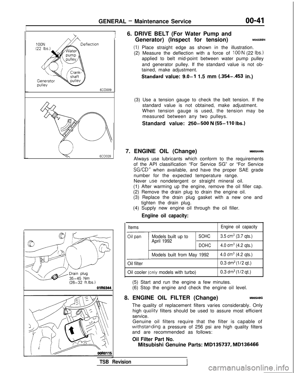
(1) Place straight edge as shown in the illustration.
(2) Measure the deflection with a force of
100 N (22 Ibs.)
applied to belt mid-point between water pump pulley
and generator pulley. If the standard value is not ob-
tained, make adjustment.
Standard value: 9.0-l 1.5 mm (.354-.453
in.)
(3) Use a tension gauge to check the belt tension. If the standard value is not obtained, make adjustment.
When tension gauge is used, the tension may be
measured between any two pulleys.
Standard value:
250-500 N (55-110
Ibs.)
7. ENGINE OIL (Change)MOOSAABc
Always use lubricants which conform to the requirements
of the API classification “For Service SG” or “For Service SG/CD”
when available, and have the proper SAE grade
number for the expected temperature range.
Never
Lose nondetergent or straight mineral oil.
(1) After warming up the engine, remove the oil filler cap.
(2) Remove the drain plug to drain the engine oil. (3) Replace the drain plug gasket with a new one and
tighten the drain plug.
(4) Supply new engine oil through the oil filler.
Engiine oil capacity:
Items Engine oil capacity
Oil pan
1
Models built up toSOHC3.5 dm3 (3.7 qts.)
April 1992DOHC4.0 dm3 (4.2 qts.)
Models built from May 19924.0 dm3 (4.2 qts.)
Oil filter 0.3 dm3 (l/2 qt.)
Oil cooler
(clnly models with turbo) 0.3 dm3 (I/2 qt.)
(5) Start and run the engine a few minutes.
(6) Stop the engine and check the engine oil level.
8. ENGINE OIL FILTER (Change)
MOOSABG
The quality of replacement filters varies considerably. Only high
quatlity filters should be used to assure most efficient
service. Genuine oil filters require that the filter is capable of
withstarlding a pressure of 256 psi are high quality filters
and are recommended as follows:
Oil Filter Part No.
Mitsubishi Genuine Parts: MD135737,
MD136466
TSB Revision
Page 51 of 1273
11-I
CONTENTSM11AA-
ENGINE
........................
53
CAMSHAFT AND CAMSHAFT OIL
SEALS..........................................68
CYLINDER HEAD GASKET
.................73
ENGINE ASSEMBLY
.........................63
OIL PAN AND OIL SCREEN ...............71
SERVICE ADJUSTMENT
PROCEDURES................................
57
Basic
Idle Speed Adjustment
...........................
.
Refer to GROUP 13
Compression Pressure Check ..............
59
Curb- Idle Speed Adjustment_.___..__._____....___._....Refer to GROUP 13
Dash Pot Inspection and Adjustment 58
Drive Belts Tension Adjustment . 6
1
Engine Oil Check . . .
_. _. . . _. . . . . . . 57
Ignition Timing Adjustment
__..._.__...................Refer to GROUP 16
Lash Adjusters Check ......................
.
57
Manifold Vacuum Inspection
..............
.
60
SPECIAL TOOLS.............................56
SPECIFICATIONS
............................53
General Specifications .....................
.
53
Sealants and Adhesives ....................
56
Service Specifications......................
.
53
Torque Specifications
......................
.
54
TIMINGBELT.................................80
TROUBLESHOOTING
........................56
E,NGINE
CAMSHAFT AND CAMSHAFT OIL
SEAL. . . . . . . . . . . . . . . . . . . ..*............ . . . . . . . . . .19
CYLINDER HEAD GASKET..................25
ENGINE ASSEMBLY.........................14
OIL PAN AND OIL SCREEN. . . . . . . . . . . . . . . .23
SERVICE ADJUSTMENT
PROCEDURES. . . . . . . . . . . . . . . . . . . . . . . ..*.......7
Basic Idle Speed Adjustment
. . . . . . . .._......... . Refer to GROUP 13
Compression Pressure Check . .
.
8
Curb Idle Speed Adjustment
.__................ _. . . . Refer to GROUP 13
Drive Belts Tension Adjustment .........
.
12
Engine Oil Check
..........................
.
7
Ignition Timing Adjustment
_...___............... . . . . . Refer to GROUP 16
Lash Adjusters Check . . . . . . . . . . . .
7
Manifold Vacuum Inspection . . . . . . . . . .9
Timing Belt Tension Adjustment . . . .10
SPECIAL TOOLS . . . . . . . . . . . . . . . . . . . . . . . . . . . . . \
.5
SPECIFICATIONS. . . . . . . . . . . . . . . . . . . . . . . . . . . . .2
General Specifications _. _.2
Sealants and Adhesives
._ _. . . . . . . .5
Service Specifications . . . .2
Torque Specifications . . . . . . . . . . . . . . . .4
TIMING BELT. . . . . . . . . . . . . . . . . . . . . . . . . . . . . . . . .34
TROUBLESHOOTING. . . . . . . . . . . . . . . . . . . . m.. .6
Compression Too Low
Connecting Rod Noise/Main Bearing Noise Excessive Engine Rolling and Vibration
Noisy Valves
Oil Pressure Drop
Oil Pressure Too High
Timing Belt Noise
Page 52 of 1273
11-2ENGINE
ENGINE
SPECIFICATIONS
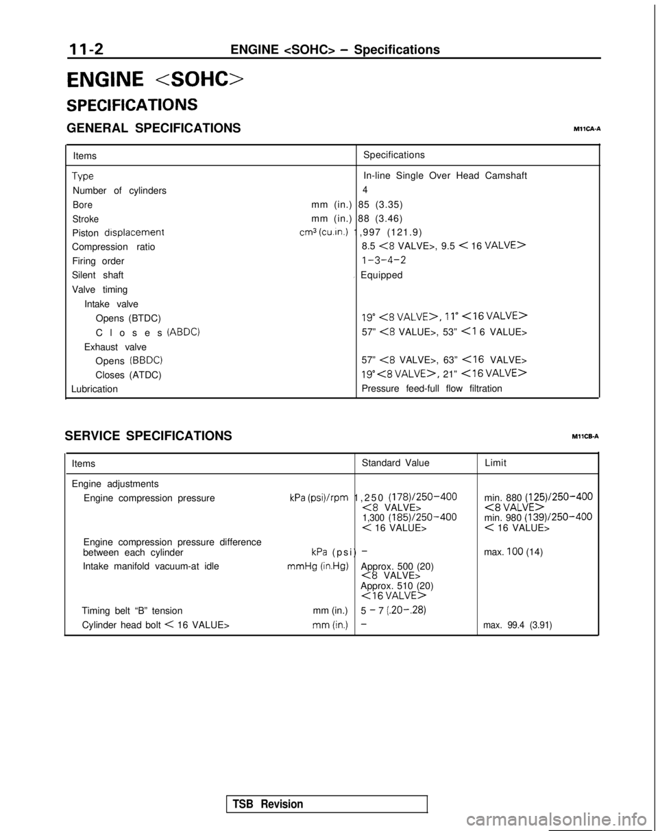
GENERAL SPECIFICATIONSMllCA-A
ItemsType
Number of cylinders
Bore
Stroke
Piston drsplacement
Compression ratio
Firing order
Silent shaft
Valve timing
Intake valveOpens (BTDC)
Closes
(ABDC)
Exhaust valveOpens
(BBDC)
Closes (ATDC)
Lubrication Specifications
In-line Single Over Head Camshaft
4
mm (in.) 85 (3.35)
mm (in.) 88 (3.46)
cm3 (cu.in.) 1,997 (121.9)
8.5
<8 VALVE>, 9.5 < 16 VALVE>
1-3-4-2
I Equipped
19”<8VALVE>,11”<16VALVE>
57” <8 VALUE>, 53”
57”
<8 VALVE>, 63”
19” , 21” <16VALVE>
Pressure feed-full flow filtration
SERVICE SPECIFICATIONS
MllCB-A
Items Standard Value
Limit
Engine adjustments Engine compression pressure
Engine compression pressure difference
between each cylinder
Intake manifold vacuum-at idle
kPa (psi)/rpm 1,250 (178)/250-400<8 VALVE>1,300 (185)/250-400< 16 VALUE>
kPa (psi) - mmHg
(in.Hg)Approx. 500 (20)<8 VALVE>
Approx. 510 (20)
<16VALUE>
min. 880 (125)/250-400<8 VALUE>min. 980 (139)/250-400< 16 VALUE>
max.
100 (14)
Timing belt “B” tension mm (in.)
5
- 7 (.20-.28)
Cylinder head bolt
< 16 VALUE>mm(in.) -max. 99.4 (3.91)
TSB Revision