1989 MITSUBISHI GALANT change wheel
[x] Cancel search: change wheelPage 1 of 1273
BACKUP
Service Manual
GRLRNT
1989-1990-1991-1992-1993
Volume 1
Chassis & Mechanical
FOREWORD
This Service Manual has been prepared with thelatest service information available at the time of
publication. It is subdivided into various group cate-
gories and each section contains diagnostic, dis-
assembly, repair, and installation procedures along
with complete specifications and tightening ref-
erences. Use of this manual will aid in properly per-
forming any servicing necessary to maintain or res-
tore the high levels of performance and reliability
designed into these outstanding vehicles.
This BACKUP DSM manual is to be used DNLY as
a SACKUP. please DIJ NOT REDISTRIBUTEWHOLE SECTIONS. This BACKUP was sold to you under the fact that you do indeed
DWNa GENUINE DSM MANUAL. It CANNOT BE considered a REPLACEMENT (Unless your
original
manual was lost or
destroyed.) Please
See
README.TXT
or
README.HTML
for additional
information.
1kyou.
- Gjmpiemym_ay&?h
@
A
.
.”
WE SUPPORT
VOLUNTARY TECHNICIAN
CERTIFICATION THROUGH
Nallonal lnsrltule forAU~~~v3~;VPCT:VE
EXCELLENCE naiLcorn
MITSUBISHIMOTOR SALES OF AMERICA. Inc.
Mltsublshl Motors Corporat!on reserves the right to make changes indesign or to make additions to or Improvements In Its products
wlthout~mposng any obllgatlons upon Itself to install them on its productspreviously manufactured
0 1992 Mitsubishi Motors CorporationRcprintedinUSA
GROUP INDEXMOOAA-
General.........................................................
Engine...........................................................
Fuel................................................................
Cooling.........................................................
Intake and Exhaust..............................
Emission Control....................................
Clutch............................................................
Manual Transaxle..................................
Automatic Transaxle............................
Propeller Shaft........................................
Front Axle..................................................
Rear Axle....................................................
Wheel and Tire.......................................
Power Plant Mount..............................
Front Suspension...................................
Active-Electronic
Control Suspension..............................m
A
Rear Suspension....................................&
Service Brakes.........................................
Parking Brakes........................................
Alphabetical Index.................................
NOTE: Electrical system Information is contained in
Volume 2 “Electrical” of this paired Service Manual.
For overhaul procedures of engines or transmissions,
refer to the separately issued Engine
Service Manual
or Manual/Automatic Transmission Service Manual.
Page 20 of 1273
00-l 8GENERAL - Towing and Hoisting
SAFETY PRECAUTIONS
The following precautions should be taken when towing thevehicle.
1.DO NOT LIFT OR TOW THE VEHICLE BY ATTACHING TO
OR WRAPPING AROUND THE BUMPER.
2. Any loose or protruding parts of damaged vehicle such as hoods, doors, fenders, trim, etc., should be secured prior to
moving the vehicle.
3.Operator should refrain from going under a vehicle while it
is lifted by the towing equipment, unless the vehicle in
adequately supported by satefy stands.
4. Never allow passengers to ride in a towed vehicle. 5. State and local rules and regulations must be followed when towing a vehicle.
Refer to the section “Special Handling Instructions for AWD
Models”.
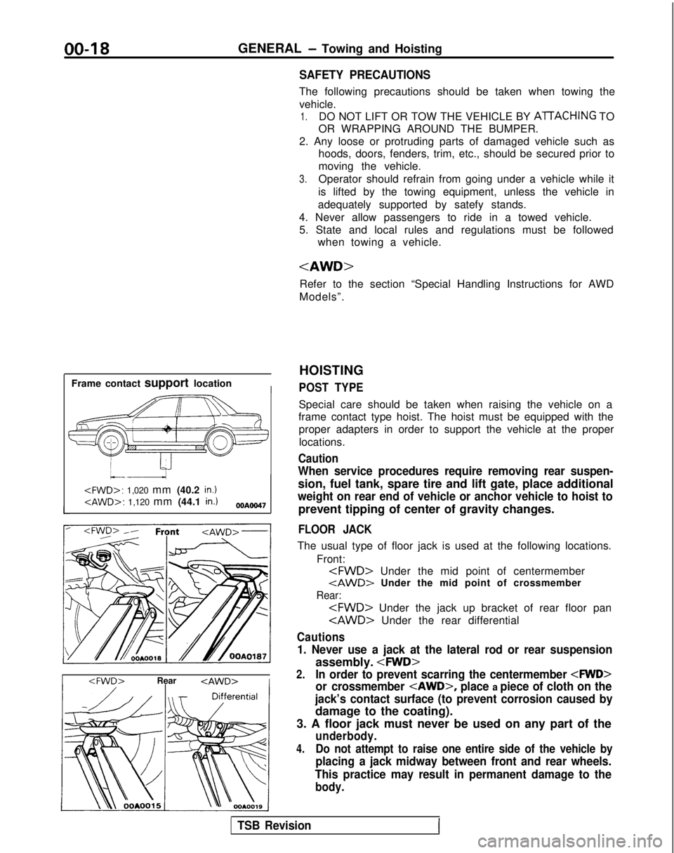
Frame contact support location
I
HOISTING
POST TYPE
Special care should be taken when raising the vehicle on a
frame contact type hoist. The hoist must be equipped with the
proper adapters in order to support the vehicle at the proper
locations.
Caution
When service procedures require removing rear suspen-
sion, fuel tank, spare tire and lift gate, place additional
weight on rear end of vehicle or anchor vehicle to hoist to
prevent tipping of center of gravity changes.
FLOOR JACK
The usual type of floor jack is used at the following locations.
Front:
tAWD> Under the mid point of crossmember
Rear:
Cautions
1. Never use a jack at the lateral rod or rear suspension
assembly.
2.In order to prevent scarring the centermember
or crossmember
place a piece of cloth on the
jack’s contact surface (to prevent corrosion caused by
damage to the coating).
3. A floor jack must never be used on any part of the
underbody.
4.Do not attempt to raise one entire side of the vehicle by
placing a jack midway between front and rear wheels.
This practice may result in permanent damage to the
body.
TSB RevisionI
Page 41 of 1273
GENERAL - Scheduled Maintenance Table/Maintenance Service00-39
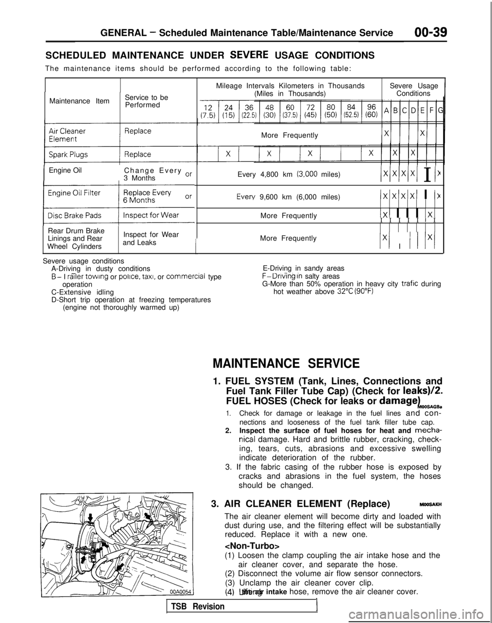
SCHEDULED MAINTENANCE UNDER SEVEiRE USAGE CONDITIONS
The maintenance items should be performed according to the following tab\
le:
Maintenance Item Service to be
Performed
IEngine Oil Change Every or
3 Months
(:z:.:a::I
Rear Drum Brake
Linings and Rear
Wheel Cylinders Inspect for Wear
and Leaks
1
Mileage Intervals Kilometers in Thousands (Miles in Thousands) Severe Usage
Conditions
More Frequently
Every 4,800 km
(3,000 miles)/xlxlx/xI I I1 Every
9,600 km (6,000 miles)
IxIxlxIxI I I>(
More Frequently1x1 I I I 1x1I I I I I I I
More Frequently
Ix1 I I I lx/
Severe usage conditions A-Driving in dusty conditions
- -B- I railer
towing or police.
taxi,
or commercial
type
operation
C-Extensive idling
D-Short trip operation at freezing temperatures (engine not thoroughly warmed up) E-Driving in sandy areas- -..F-Dnvlng In salty areas
G-More than 50% operation in heavy city trafic during
hot weather above 32°C (90°F)
MAINTENANCE SERVICE
1. FUEL SYSTEM (Tank, Lines, Connections and
Fuel Tank Filler Tube Cap) (Check for leaks)/2.
FUEL HOSES (Check for leaks or
damagekOOSnOB.
1.Check for damage or leakage in the fuel lines and con-
nections and looseness of the fuel tank filler tube cap.
2. Inspect the surface of fuel hoses for heat and mecha-
nicall damage. Hard and brittle rubber, cracking, check-
ing, tears, cuts, abrasions and excessive swelling
indicate deterioration of the rubber.
3. If the fabric casing of the rubber hose is exposed by cracks and abrasions in the fuel system, the hoses
should be changed.
3. AIR CLEANER ELEMENT (Replace)
MMlSAKH
The air cleaner element will become dirty and loaded with dust during use, and the filtering effect will be substantiallyreduced. Replace it with a new one.
(1) Loosen the clamp coupling the air intake hose and the air cleaner cover, and separate the hose.
(2) Disconnect the volume air flow sensor connectors.
(3) Unclamp the air cleaner cover clip.
(4) Lifting the air intake hose, remove the air cleaner cover.
TSB Revision1
Page 46 of 1273
GENERAL -Maintenance Service
(1O)Star-t engine and allow to idle for at least two minutes.
Then, with parking brake on, move selector
fever
momentarily to each position, ending in “N” Neutral
position.
(11)Add sufficient ATF to bring fluid level to lower mark.
Recheck fluid level after transaxle is at normal Operating
temperature. Fluid level should be between upper and lower marks of
“HOT” range, Insert dipstick fully to prevent dirt from
entering transaxle.
OOA0051
11 .ENGINE
COOLANT (Change)MOOSEEAC
Check the cooling system parts, such as radiator, heater,
and oil cooler hoses, thermostat and connections for
leakage and damage.
CHANGE COOLANT
1. Remove the radiator cap.
2. Loosen the drain plug to drain the coolant.
3. Drain the coolant from the reserve tank.
4. After draining the coolant, tighten the drain plug securely.
5.Supply the coolant into the radiator until it is filled up to
its filler neck.
6. Supply the coolant into the reserve tank.
7. After warming the engine until the thermostat opens, remove the radiator cap and check the coolant level.
8.Supply the coolant into the radiator until it is filled up to
its filler neck, and install the radiator cap securely.
9.Fill the reserve tank with coolant up to the “FULL” line.
14K512
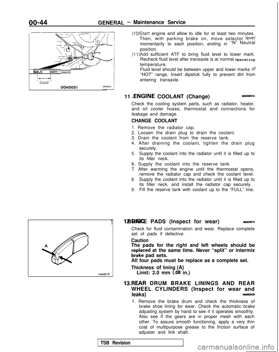
1 12.DISC BRAKE PADS (Inspect for wear) MWSBFA
Check for fluid contamination and wear. Replace complete
set of pads if defective.
Caution
The pads for the right and left wheels should be
reDlaced at the same time. Never “split” or intermix
brkke pad sets.
All four pads must be replace as a complete set.
Thickness of lining (A)
Limit: 2.0 mm (.08 in.)
13.REAR DRUM BRAKE LININGS AND REAR
WHEEL CYLINDERS (Inspect for wear and
leaks)MOOSBGB
1. Remove the brake drum and check the thickness of brake shoe lining for wear. Check the automatic brake
adjusting system by hand to see if it operates smoothly.
Also see if the gears are in proper mesh with each
other. To assure smooth functioning, apply a very thin
coat of multipurpose grease to the friction surface of
adjuster and link shaft.
TSB Revision1
Page 161 of 1273
FUEL SYSTEM
PROBLEM SYMPTOMS TABLE (FOR YOURINFORMATION)
:tShock
Surge
Knocking
0,GRun ona (“dieselrng”)
6
Items Symptom
-- -... __----. -~-
The starter IS used to crank the engine, but there IS no
combustron
wrthrn
the cylinders.
(no rnrtral combustron)
and the engine won’t start~-.-__Startrng
problem There IS combustron
wrthrn
the cylrnders.
but then the engrne
soon stalls.
(Initial combustion, then stall)
(Startrng takes a long t1me.l
I
Idling
rnstabrlrty
/ Engrne won’t start qurckly~--_~ -...
Engine speed doesn’t remain constant; changes during idling.
Usually, aludgement can be based upon the movement of the tachometer pointer, and
the
vibration transmitted to the steering wheel, shift lever, body, etc. This is call\
ed rougt
Idling.
The
engtnedoesn’t idle at the usual correct speed.
Thus non-contrnuity of rdlrng Includes the followrng elements(1) Die out
. . . . ..The
engine stalls when the foot IS taken from the accelator pedal,
regardless of whether the vehicle IS moving or not.(2)Pass out . . . ..The
engine stalls when the accelerator pedal IS depressed or while it IS berng
used.
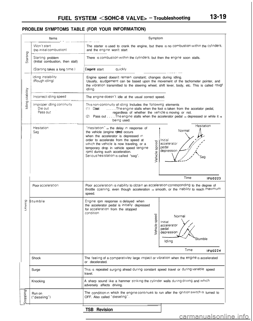
“Hestatton” IS the delay In response of
the vehicle (engine rpm) that occurs
when the accelerator is depressed
Inorder to accelerate from the speed atwhich the vehicle is now traveling, or a
temporary drop in vehicle speed (enginerpm) during such acceleration. Hesltatron
Serious
hesstatlon IS called “sag”.
Poor
acceleration
E Stumbl
e
2
5
Time lFUO223
Poor
acceleration IS rnabilrty
to obtain an acceleration corresponding to the degree of
throttle opening, even though acceleration IS smooth, or the rnabrlrty to reach maxmum
speed.
Engrne rpm response IS delayed when .
the accelerator pedal is initrally
depressed
for acceleratron
from the stopped
condition ldllng
Stumble
Trme lFUO224
The
feeling of a comparatlvley large Impact or vrbration
when the engine IS accelerated
or decelerated.
This IS repeated surging
ahead dunng constant speed travel or dunng
vanable
speed
travel.
A sharp sound
IIke a hammer strtklng the cylinder walls during
dnvtng
and whrch
adversely affects driving.
The
condrtion In which the engrne
continues to run after the lgnltion switch 1s turned to
OFF. Also called
“dreselrng”.
TSB Revision
Page 224 of 1273
13-82 FUEL SYSTEM
OPERATION
l The power-steering pressure switch functions
to convert data as to whether there is or is not apower steering load to LOW-or HIGH-level vol-
tage, and the resulting signals are input to the engine control module. The engine control mod-
ule, based upon those signals, regulates the
idle-speed control motor. l The battery voltage within the engine control
module is applied, by way of the resistance, to
the power-steering pressure switch. When
steering maneuvers are made, the pressure of
the power-steering oil increases, thus switching
ON the power-steering pressure switch, with
the result that the current is grounded. As a re-
sult, the power-steering pressure switch vol-
tage changes from HIGH level to LOW level.
INSPECTION I) Using Scan tool
Function
Item No.
Data reading 27
Data displayInspection conditions Steering wheelNormal indication
Switch status Engine: IdlingSteering wheel idle stateOFF
During steering wheelONoperation
(2) Checking Oil Pressure
Steering wheel
Straight forward
Turned
Oil pump delivery pressure (ref. value)
less than 1,470- 1,961 kPa (213-284 psi)
more than
1,470- 1,961 kPa (213-284 psi)
HARNESS INSPECTION
I-E-I
Harness side connector 6 0
@=- -0
Q
4 1
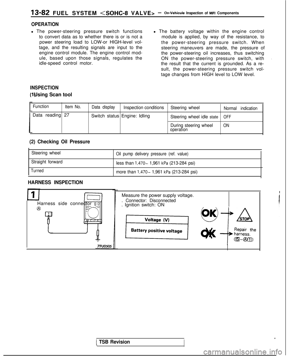
Measure the power supply voltage.
. Connector: Disconnected. Ignition switch: ON
[ TSB Revision
Page 335 of 1273
FUEL SYSTEM
TerminaNo.
19
52
-rII
i
t
c
65
L
63
64t
I:
I
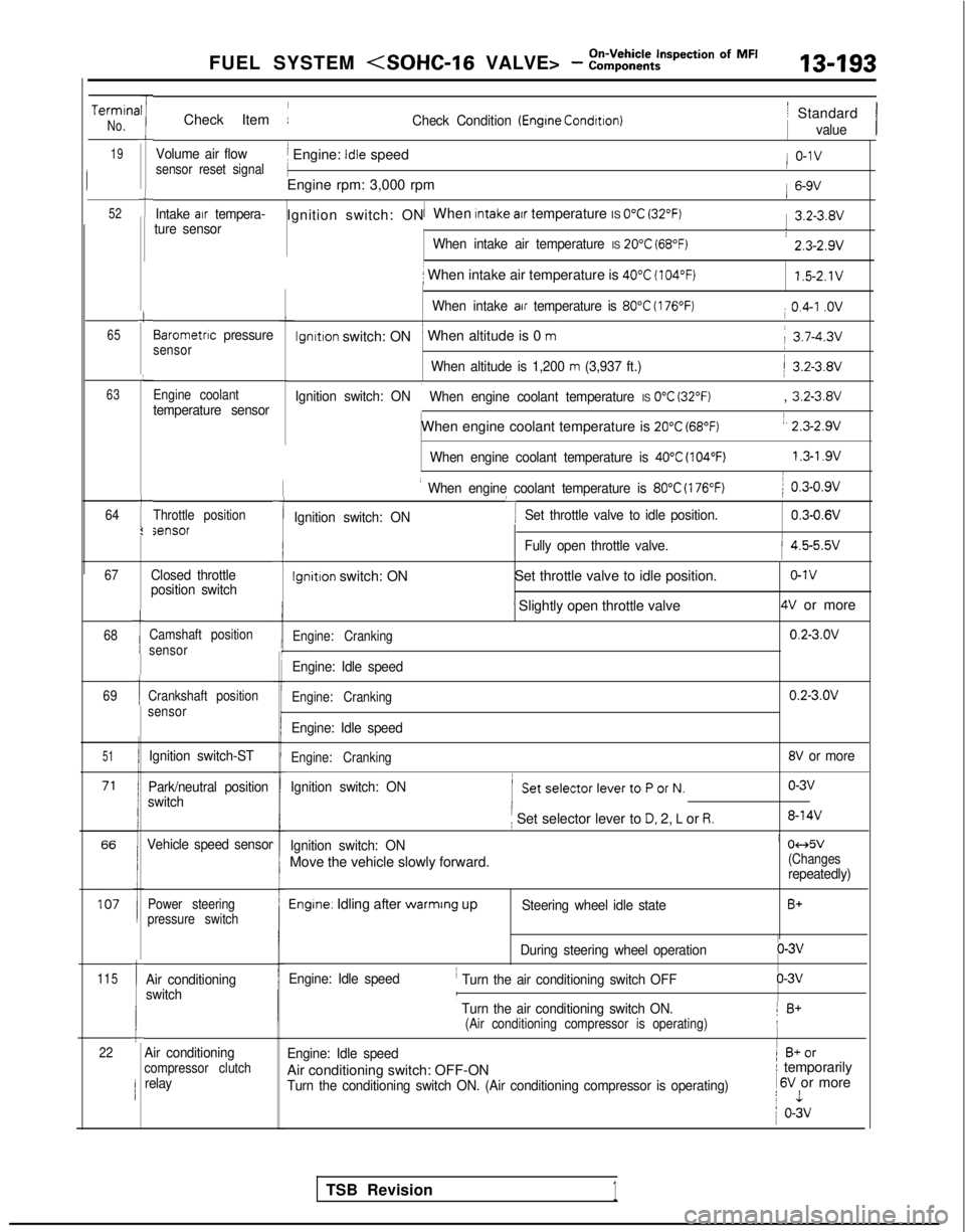
Check Item :Check Condition (Engrne Condrtron)
Volume air flowj Engine: Idle speedsensor reset signal
1
Engine rpm: 3,000 rpm
Intake air tempera-1Ignition switch: ON When Intake atr temperature IS 0°C (32°F)ture sensor
When intake air temperature IS 20°C (68°F)
i When intake air temperature is 40°C (104°F)
When intake air temperature is 80°C (176°F)
lgnltlon switch: ON’ When altitude is 0 m
When altitude is 1,200 m (3,937 ft.)
Ignition switch: ON
i When engine coolant temperature IS 0°C (32°F)
When engine coolant temperature is 20°C (68°F)
When engine coolant temperature is 40°C (104°F)
Barometnc pressuresensor
Engine coolant
temperature sensor
Throttle positionsensor
67
68
69
51
115
1
1
Ic22
Closed throttle
position switch
Camshaft position
sensor
Crankshaft position
sensor
Ignition switch-ST
Park/neutral position
switch
Vehicle speed sensor
Power steering
pressure switch
Air conditioning
switch
-I
I When engine coolant temperature is 80°C (176°F)
‘I
) 0.3-0.9v
Ignition switch: ON Set throttle valve to idle position.
0.3-0.6V
iFully open throttle valve.1 4.5-5.5v
Ignition switch: ON
Set throttle valve to idle position.o-1v
’ Slightly open throttle valve4V or more
Engine: Cranking0.2-3.OV
Engine: Idle speed
Engine: Cranking0.2-3.OV
Engine: Idle speed
Engine: Cranking8V or more
Ignition switch: ON
( SetselectorlevertoPorN.o-3v
i Set selector lever to D. 2, L or R.8-14V
Ignition switch: ONi 04d5v
Move the vehicle slowly forward.(Changesrepeatedly)
Engine. Idling after warmrng upSteering wheel idle stateB+
During steering wheel operationo-3v
Engine: Idle speed
’ Turn the air conditioning switch OFFo-3vI
’ Turn the air conditioning switch ON.1 B+(Air conditioning compressor is operating)!
Engine: Idle speed1 B+or
Air conditioning switch: OFF-ONI temporarily
Turn the conditioning switch ON. (Air conditioning compressor is operat\
ing) 1
6V or morej 1
1 o-3v
/ Standard
value
/ o-1v
1 6-9V
1 3.2-3.8V
: 2.3-2.9v
1.5-2.1V
i 0.4-I .ov
j 3.7-4.3v
/ 3.2-3.8V
, 3.2-3.8V
1, 2.3-2.9v
1.3-l .9vI
Air conditioningcompressor clutchrelay
TSB Revision1
Page 355 of 1273
FUEL SYSTEM
PROBLEM SYMPTOMS TABLE(FORYOUR
INFORMATION) Item
Symptom
Won’t start The starter IS used to crank the engine, but there is no combustron
withrn
tht(no inrtial combustion)
cylinders, and the engine won’t start.
p Starting problem There is combustion within the cylinders, but then the engine soon stalls.g
$$a combustion, then
5
(Starting takes a long Engine won’t start quickly.
time.)
Idling instability (Rough Engine speed doesn’t remain constant; changes du\
ring idling.idling)Usually, a judgment can be based upon the movement of the tachometer poi\
nter
and the vibration transmitted to the steering wheel, shift lever, body, \
etc. This i:>.ccalled rough idling.=
%zIncorrect idling speed The engine doesn’t Idle at the usual correct speed.
F
Improper
idling continui-
This non-continuity of idling includes the following elements.-0tY (I 1 Die out .._.__... The engine stalls when the foot is taken from the accelerator-Die out
pedal, regardless of whether the vehicle is moving or not.
Pass out(2) Pass out .._.... The engine stalls when the accelerator pedal is depressed 01while it is being used.
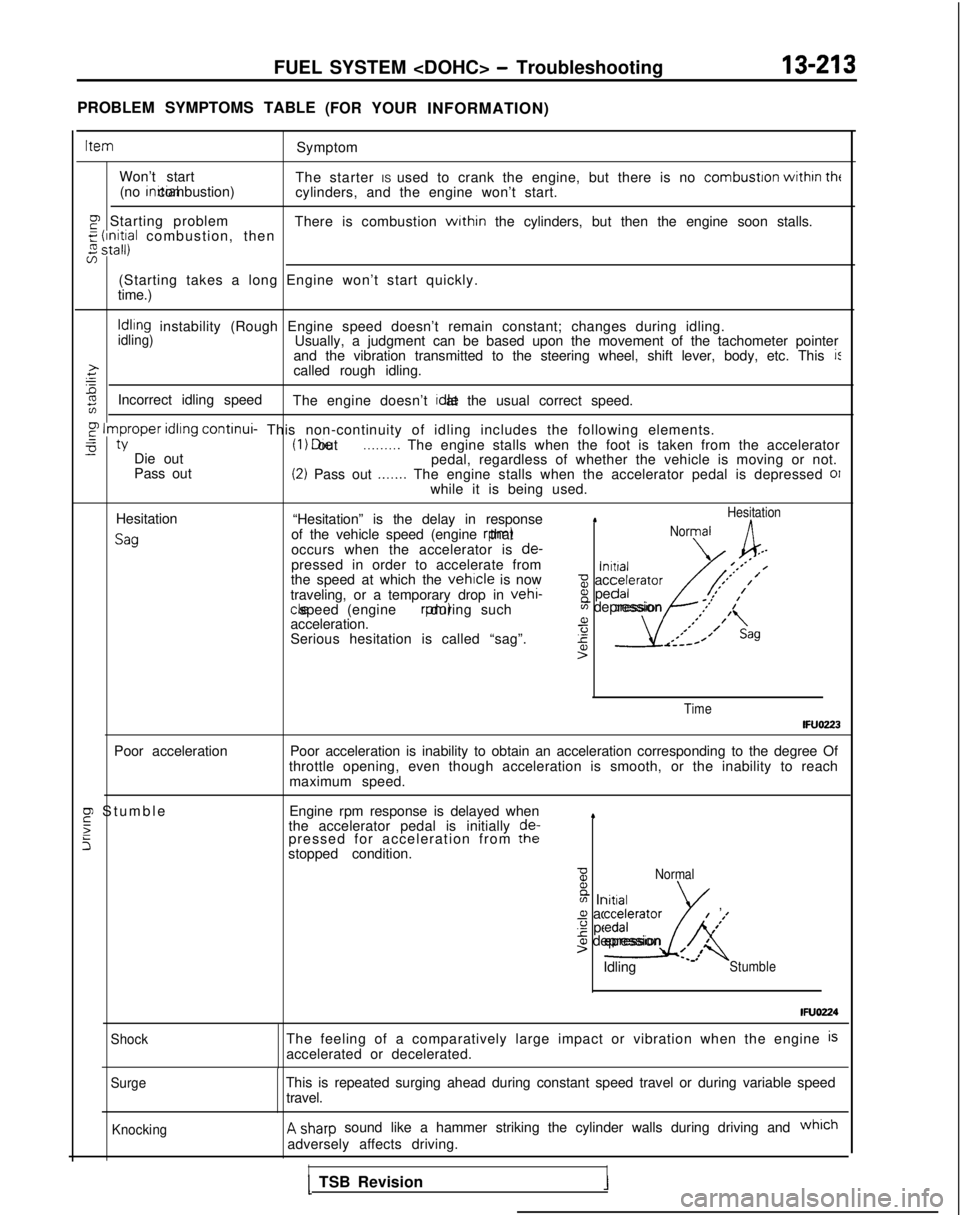
Hesitation
Sag
“Hesitation” is the delay in response1Hesitation
of the vehicle speed (engine rpm) thatNormal
occurs when the accelerator is
de-,--pressed in order to accelerate from\alnrtral-’‘** /the speed at which the vehicle is nowz accelerator,’ ’
traveling, or a temporary drop in vehi-8 pedal/*’
,’ ,’
cle speed (engine rpm) during such
acceleration. a
Serious hesitation is called “sag”.
4sAK
m depression .I’
1’
,’*;’ I(,
r-----
4’>
Time
IFUOZ23
Poor acceleration Poor acceleration is inability to obtain an acceleration corresponding t\
o the degree Of
throttle opening, even though acceleration is smooth, or the inability t\
o reach maximum speed.
F Stumbl
e
5
5
Engine rpm response is delayed when
the accelerator pedal is initially de-
pressed for acceleration from the
stopped condition.4
BNormal B
m Initiala acceleratorg pedal
I
’
-2
/#’
01 depression4t’>’ /Idling L’Stumble
IFUO224
ShockThe feeling of a comparatively large impact or vibration when the engine\
isaccelerated or decelerated.
SurgeThis is repeated surging ahead during constant speed travel or during va\
riable speed
travel.
KnockingA sharp sound like a hammer striking the cylinder walls during driving and which
adversely affects driving.
II1 TSB Revision1