1989 MITSUBISHI GALANT light
[x] Cancel search: lightPage 18 of 1273
00-l 6GENERAL - Precautions before Service
Caution
1. Before connecting or disconnecting the negative
cable, be sure to turn off the ignition switch and the
lighting switch.
(If this is not done,there is the possibility of
semiconductor parts being damaged.)
2.For MFI-equipped models, after completion of the
work steps [when the battery’s negative (-) termi-
nal is connected], warm up the engine and allow it
to idle for approximately five minutes under the
conditions described below, in order to stabilize
engine control conditions, and then check to be
sure that the idling is satisfactory.
Engine coolant temperature:
85-95X (185-203°F)
Lights, electric fans, accessories: OFF
Transaxle: neutral position (A/T models: “N” or
“P”)
Steering wheel:neutral (center) position
mm (tn.1
Scan Tool(Multi-use tester
ROM pack
1
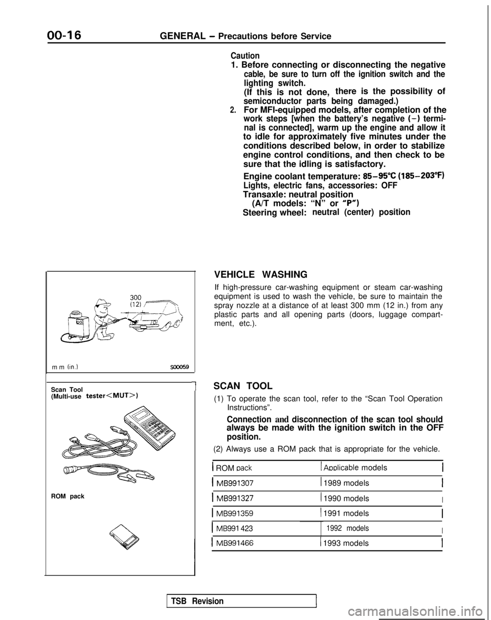
VEHICLE WASHING
If high-pressure car-washing equipment or steam car-washing
equipment is used to wash the vehicle, be sure to maintain the
spray nozzle at a distance of at least 300 mm (12 in.) from any plastic parts and all opening parts (doors, luggage compart-
ment, etc.).
SCAN TOOL (1) To operate the scan tool, refer to the “Scan Tool Operation Instructions”.
Connection and disconnection of the scan tool should
always be made with the ignition switch in the OFF
position.
(2) Always use a ROM pack that is appropriate for the vehicle.
1 ROM oack1 Aoblicable models
1 MB9913071 1989 modelsI
1 MB9913271 1990 modelsI
1 MB991359( 1991 models
IMB991 4231992 modelsI
1 MB9914661 1993 models
TSB Revision
Page 30 of 1273
00-28GENERAL - Tightening Torque/Master Troubleshooting
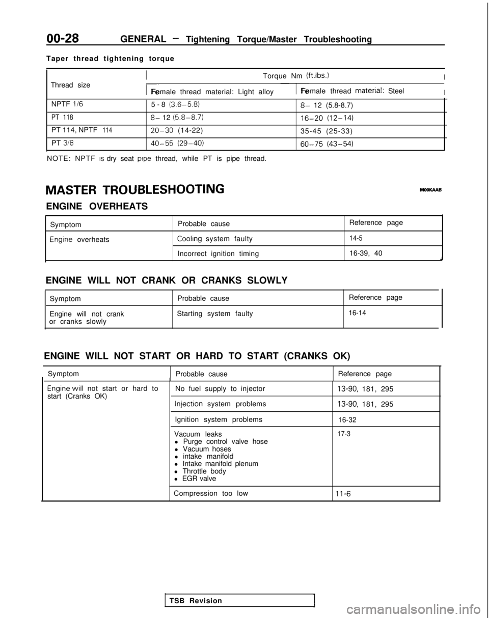
Taper thread tightening torque
Thread size
ITorque Nm (ftlbs.)I
r~Female thread material: Light alloy1-Female thread material: SteelI
NPTF II65-8 (3.6-5.8)
PT 1188- 12 (5.8-8.7)
PT 114, NPTF11420-30 (14-22)
PT
31840-55 (29-40)
NOTE: NPTF IS dry seat pope thread, while PT is pipe thread.
8- 12 (5.8-8.7)
16-20 (12-14)
35-45 (25-33)
60-75 (43-54)
MASTER TROUBLESHOOTING hlooKAAB
ENGINE OVERHEATS Symptom
Engine overheats Probable cause
Reference pageCoolrng system faulty14-5
Incorrect ignition timing
16-39, 40
ENGINE WILL NOT CRANK OR CRANKS SLOWLY Symptom Probable cause
Engine will not crank Starting system faulty
or cranks slowly Reference page
16-14
ENGINE WILL NOT START OR HARD TO START (CRANKS OK)
Symptom Probable cause Reference page
Engrne WIII not start or hard to
start (Cranks OK) No fuel supply to injector Injection
system problems
Ignition system problems
Vacuum leaks l Purge control valve hose
l Vacuum hoses
l intake manifold
l Intake manifold plenum
l Throttle body
l EGR valve13-90, 181, 295
13-90, 181, 295
16-32
17-3
Compression too low11-6
TSB Revision
Page 47 of 1273
14KO24
OOA0186
GENERAL - Maintenance Service00-45
2.Inspect the wheel cylinder boots for evidence of a brake
fluid leak. Visually check the boots for cuts, tears or heat cracks. (A slight amount of fluid on the boot may
not be a leak, but may be preservative fluid used at
assembly.)
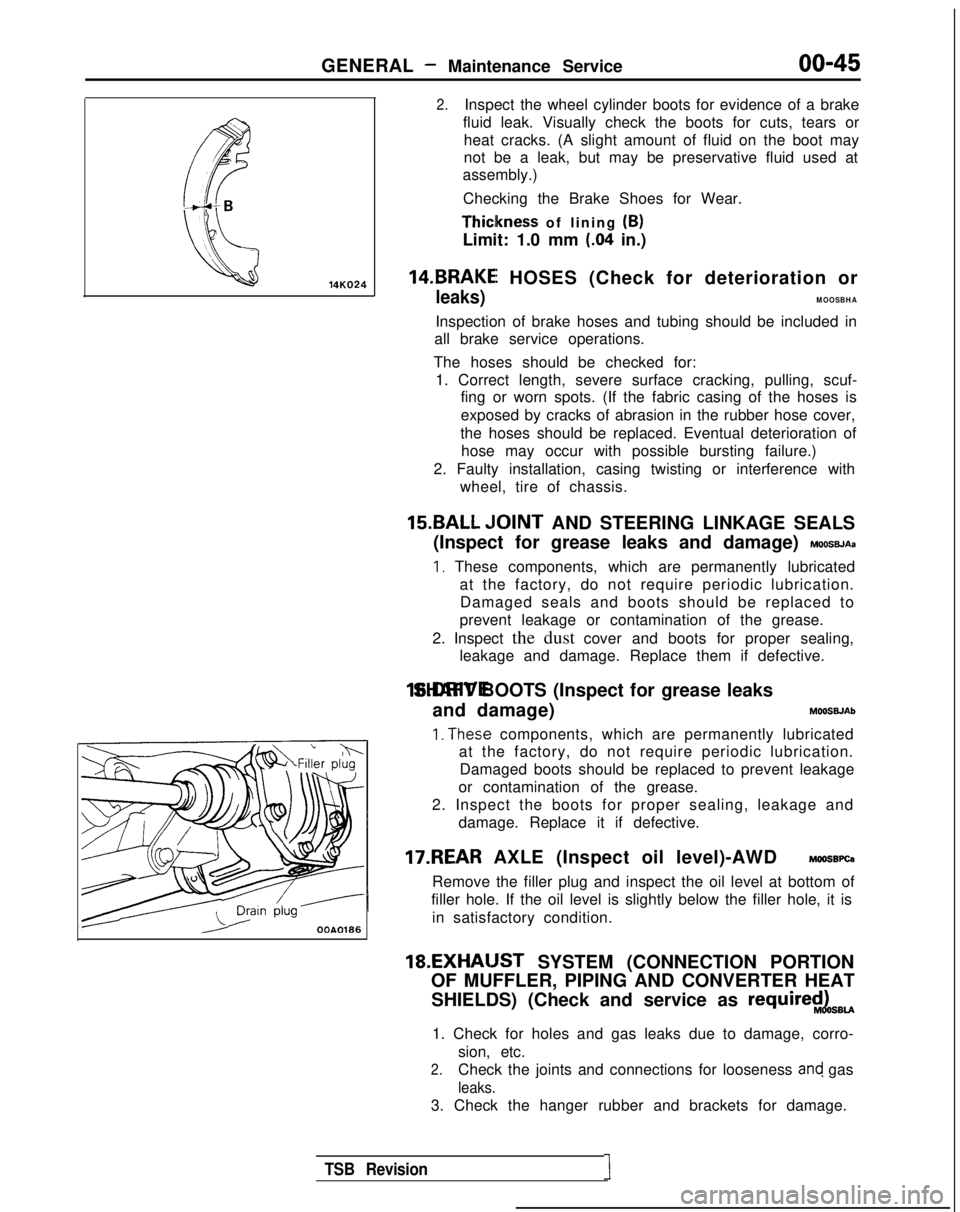
Checking the Brake Shoes for Wear. Thiclkness
of lining (B)
Limit: 1.0 mm
(.04 in.)
14.BRAKEI HOSES (Check for deterioration or
leaks)MOOSBHA
Inspection of brake hoses and tubing should be included in
all brake service operations.
The hoses should be checked for: 1. Correct length, severe surface cracking, pulling, scuf- fing or worn spots. (If the fabric casing of the hoses is
exposed by cracks of abrasion in the rubber hose cover,
the hoses should be replaced. Eventual deterioration of hose may occur with possible bursting failure.)
2. Faulty installation, casing twisting or interference with wheel, tire of chassis.
15.BALL ,IOINT AND STEERING LINKAGE SEALS
(Inspect for grease leaks and damage)
MOOSBJAa
I, These components, which are permanently lubricated at the factory, do not require periodic lubrication.Damaged seals and boots should be replaced to
prevent leakage or contamination of the grease.
2. Inspect the dust cover and boots for proper sealing, leakage and damage. Replace them if defective. 16.DRIVE SHAFT BOOTS (Inspect for grease leaks
and damage) MOOSWAb
1. The.se components, which are permanently lubricated
at the factory, do not require periodic lubrication.
Damaged boots should be replaced to prevent leakage
or contamination of the grease.
2. Inspect the boots for proper sealing, leakage and damage. Replace it if defective.
17.REAR AXLE (Inspect oil level)-AWD MOOSBPQ
Remove the filler plug and inspect the oil level at bottom of
filler hole. If the oil level is slightly below the filler hole, it is
in satisfactory condition. 18.EXHAIJST
SYSTEM (CONNECTION PORTION
OF MUFFLER, PIPING AND CONVERTER HEAT
SHIELDS) (Check and service as
require$LsBU
1. Check for holes and gas leaks due to damage, corro- sion, etc.
2.Check the joints and connections for looseness and gas
leaks.
3. Check the hanger rubber and brackets for damage.
TSB Revision1
Page 48 of 1273
00-46GENERAL - Table of Main Sealants and Adhesives
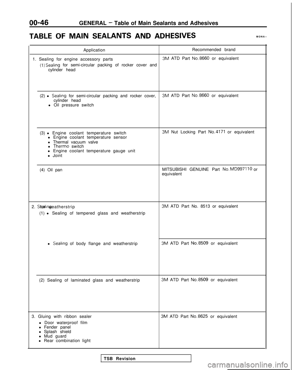
TABLEOF MAINSEALANTS
AND
ADHESIVES
MONA--
Application Recommended brand
1. Sealing for engine accessory parts 3M
ATD Part No.8660
or equivalent
(1) Sealing
for semi-circular packing of rocker cover and
cylinder head
(2) l
Sealrng for semi-circular packing and rocker cover, 3M
ATD Part No.8660
or equivalent
cylinder head
l Oil pressure switch
(3) l Engine coolant temperature switch l Engine coolant temperature sensor
l Thermal vacuum valvel Therm0
switch
l Engine coolant temperature gauge unit
l Joint 3M
Nut Locking Part
No.4171 or equivalent
(4) Oil pan MITSUBISHI GENUINE Part No.MD997110
or
equivalent
2. Sealing for weatherstrip
(1) l Sealing of tempered glass and weatherstrip 3M
ATD Part No. 8513 or equivalent
l Sealing
of body flange and weatherstrip 3M
ATD Part No.8509
or equivalent
(2) Sealing of laminated glass and weatherstrip 3M
ATD Part No.8509
or equivalent
3. Gluing with ribbon sealer l Door waterproof film
l Fender panel
l Splash shield
l Mud guard 3M
ATD Part No.8625
or equivalent
l Rear combination light TSB Revision
Page 58 of 1273
II-8ENGINE
8 VALVE
W Tlmlng belt side
il6
16
727
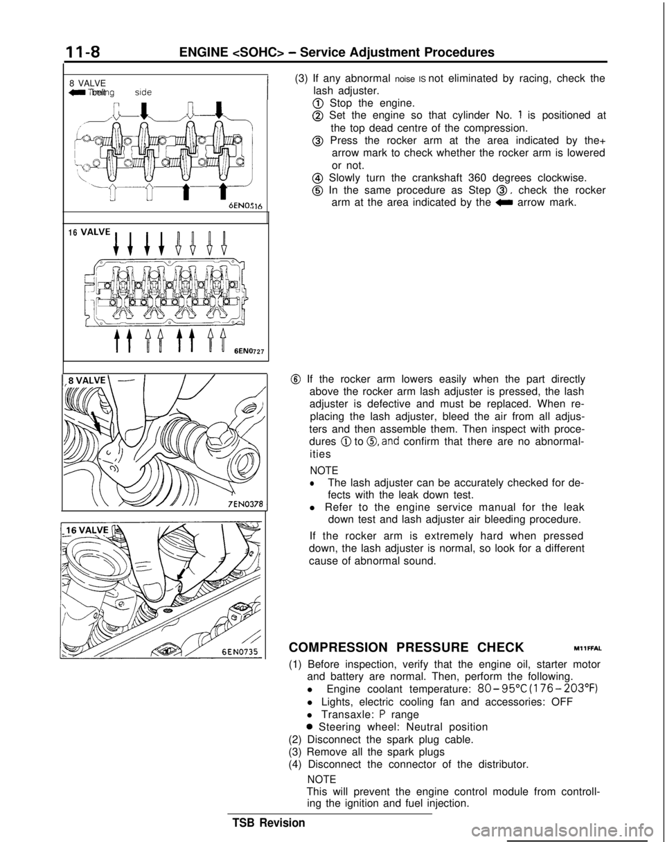
(3) If any abnormal noise IS not eliminated by racing, check the
lash adjuster.
@ Stop the engine.
@ Set the engine so that cylinder No. 1 is positioned at
the top dead centre of the compression.
@ Press the rocker arm at the area indicated by the+ arrow mark to check whether the rocker arm is lowered
or not.
@ Slowly turn the crankshaft 360 degrees clockwise.
@ In the same procedure as Step 0, check the rocker
arm at the area indicated by the
0 arrow mark.
@ If the rocker arm lowers easily when the part directly
above the rocker arm lash adjuster is pressed, the lash
adjuster is defective and must be replaced. When re-
placing the lash adjuster, bleed the air from all adjus-
ters and then assemble them. Then inspect with proce-
dures
@ to 0, and confirm that there are no abnormal-
ities
NOTE
lThe lash adjuster can be accurately checked for de-
fects with the leak down test.
l Refer to the engine service manual for the leak down test and lash adjuster air bleeding procedure.
If the rocker arm is extremely hard when pressed
down, the lash adjuster is normal, so look for a different
cause of abnormal sound.
COMPRESSION PRESSURE CHECK
MllFFAL
(1) Before inspection, verify that the engine oil, starter motor and battery are normal. Then, perform the following.
l Engine coolant temperature:
80- 95°C
(176- 203°F)
l Lights, electric cooling fan and accessories: OFF
l Transaxle:
P range
0 Steering wheel: Neutral position
(2) Disconnect the spark plug cable.
(3) Remove all the spark plugs
(4) Disconnect the connector of the distributor.
NOTE
This will prevent the engine control module from controll- ing the ignition and fuel injection.
TSB Revision
Page 101 of 1273
ENGINE
r
L Camshaft sprocket
Idler
pulley
/Oil pumpOlA0668
sprocket
6EN0175
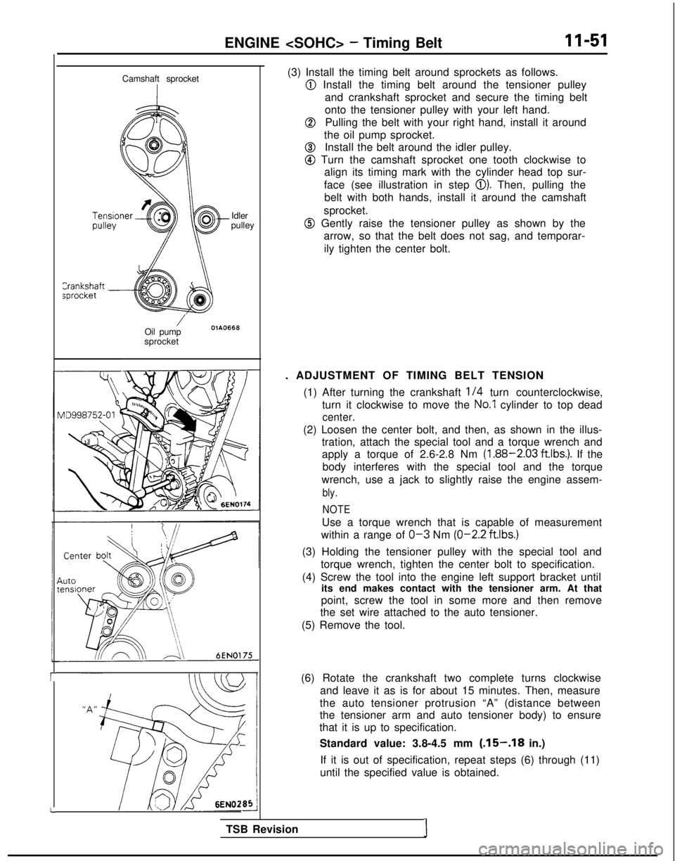
(3) Install the timing belt around sprockets as follows.
@ Install the timing belt around the tensioner pulley
and crankshaft sprocket and secure the timing belt
onto the tensioner pulley with your left hand.
@Pulling the belt with your right hand, install it around
the oil pump sprocket.
@Install the belt around the idler pulley.
@ Turn the camshaft sprocket one tooth clockwise to align its timing mark with the cylinder head top sur-
face (see illustration in step
0). Then, pulling the
belt with both hands, install it around the camshaft
sprocket.
@ Gently raise the tensioner pulley as shown by the arrow, so that the belt does not sag, and temporar-
ily tighten the center bolt.
. ADJUSTMENT OF TIMING BELT TENSION (1) After turning the crankshaft
l/4 turn counterclockwise,
turn it clockwise to move the
No.1 cylinder to top dead
center.
(2) Loosen the center bolt, and then, as shown in the illus- tration, attach the special tool and a torque wrench and
apply a torque of 2.6-2.8 Nm
(1.88-2.03 ft.lbs.). If the
body interferes with the special tool and the torque
wrench, use a jack to slightly raise the engine assem-
bly.
NOTE
Use a torque wrench that is capable of measurement
within a range of
O-3 Nm (O-2.2
ftlbs.)
(3) Holding the tensioner pulley with the special tool and
torque wrench, tighten the center bolt to specification.
(4) Screw the tool into the engine left support bracket until its end makes contact with the tensioner arm. At that
point, screw the tool in some more and then remove
the set wire attached to the auto tensioner.
(5) Remove the tool.
(6) Rotate the crankshaft two complete turns clockwise and leave it as is for about 15 minutes. Then, measure
the auto tensioner protrusion “A” (distance between
the tensioner arm and auto tensioner body) to ensure
that it is up to specification.
Standard value: 3.8-4.5 mm
(.15-.18 in.)
If it is out of specification, repeat steps (6) through (11)
until the specified value is obtained.
TSB Revision
I
Page 108 of 1273
11-58ENGINE
4 Timing belt sideI
6EN0515
(3) lf
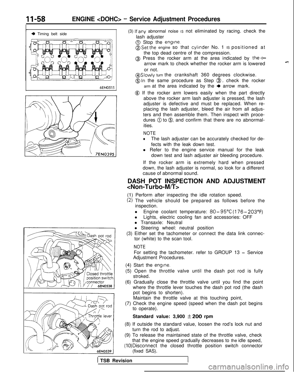
any abnormal noise IS not eliminated by racing. check the
lash adjuster
@ Stop the engine.
@ Set the engine so that cylinder
No. 1 IS positioned at
the top dead centre of the compression.
@ Press the rocker arm at the area indicated by the+
arrow mark to check whether the rocker arm is lowered
or not.
@ Slowly turn the crankshaft 360 degrees clockwise.
@ ln the same procedure as Step 0, check the rocker
arm at the area indicated by the
4 arrow mark.
@ If the rocker arm lowers easily when the part directly above the rocker arm lash adjuster is pressed, the lash
adjuster is defective and must be replaced. When re- placing the lash adjuster, bleed the air from all adjus-
ters and then assemble them. Then inspect with proce- dures
@I to 0, and confirm that there are no abnormal-
ities.
NOTE
lThe lash adjuster can be accurately checked for de-
fects with the leak down test.
l Refer to the engine service manual for the leak
down test and lash adjuster air bleeding procedure.
If the rocker arm is extremely hard when pressed
down, the lash adjuster is normal, so look for a different
cause of abnormal sound.
DASH POT INSPECTION AND ADJUSTMENT
(1) Perform after inspecting the idle rotation speed.
(2) The vehicle should be prepared as follows before the inspection.
l Engine coolant temperature:
80- 95°C
(176- 203°F)
lLights, electric cooling fan and accessories: OFF
l Transaxle: Neutral
l Steering wheel: neutral position
(3) Either set the tachometer or connect the data link connec- tor (white) to the scan tool.
NOTE
For setting the tachometer. refer to GROUP 13 - Service
Adjustment Procedures.
(4) Start the
engine.
(5) Open the throttle valve until the dash pot rod is fully
stroked.
(6) Gradually close the throttle valve until you find the point where the throttle lever touches the dash pot rod (the dashpot begins to shorten).
Maintain the throttle valve at this touching point,
(7) Check the engine speed (speed when the dash pot begins to operate).
Standard value: 3,900
f 200 rpm
(8) If outside the standard value, loosen the rod’s lock nut and turn the rod to adjust.
(9) To release the maintained state of the throttle valve, check that the engine speed gradually decreases to the idle speed, (10)Disconnect
the closed throttle position switch connector
(fixed SAS).
1 TSB Revision
Page 109 of 1273
ENGINE
7 Go;;ikv position
switch
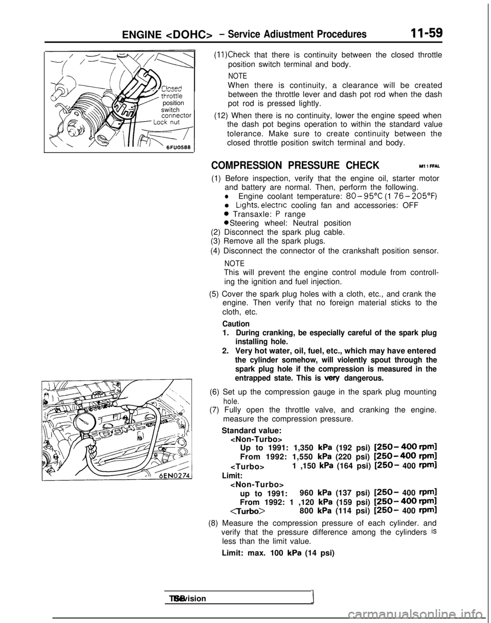
(11)Check that there is continuity between the closed throttle
position switch terminal and body.
NOTE
When there is continuity, a clearance will be created between the throttle lever and dash pot rod when the dash
pot rod is pressed lightly.
(12) When there is no continuity, lower the engine speed when the dash pot begins operation to within the standard value
tolerance. Make sure to create continuity between the
closed throttle position switch terminal and body.
COMPRESSION PRESSURE CHECK Ml 1 FFAL
(1) Before inspection, verify that the engine oil, starter motor
and battery are normal. Then, perform the following.
lEngine coolant temperature: 80- 95°C
(1 76- 205’F)
l Lights, electnc
cooling fan and accessories: OFF
0 Transaxle: P range 0 Steering wheel: Neutral position
(2) Disconnect the spark plug cable.
(3) Remove all the spark plugs.
(4) Disconnect the connector of the crankshaft position sensor.
NOTE
This will prevent the engine control module from controll- ing the ignition and fuel injection.
(5) Cover the spark plug holes with a cloth, etc., and crank the engine. Then verify that no foreign material sticks to the
cloth, etc.
Caution
1.During cranking, be especially careful of the spark plug
installing hole.
2. Very hot water, oil, fuel, etc., which may have entered
the cylinder somehow, will violently spout through the
spark plug hole if the compression is measured in the
entrapped state. This is
vex/ dangerous.
(6) Set up the compression gauge in the spark plug mounting
hole.
(7) Fully open the throttle valve, and cranking the engine.
measure the compression pressure.
Standard value:
kPa (192 psi) [250- 400 rpml
From 1992: 1,550
kPa (220 psi) [250-400 rpm]
Limit:
up to 1991: 960
kPa (137 psi) [250- 400 rpml
From 1992: 1 ,120 kPa (159 psi) [250- 400 rpml
CTurbo>
800
kPa (114 psi) [250- 400 rpml
(8) Measure the compression pressure of each cylinder. and verify that the pressure difference among the cylinders
is
less than the limit value.
Limit: max. 100
kPa (14 psi) TSB Revision
I