1989 MITSUBISHI GALANT light
[x] Cancel search: lightPage 110 of 1273
II-60ENGINE
(9) If a cylinder’s compression pressure or pressure differenceis outside the limit, fill a small amount of engine oil through
the spark plug hole and repeat Items (7) and (8) above.
@ If the compression is increased when the oil is filled, the piston
and/or cylinder wall may be worn or
damaged.
@ If the compression is not Increased even though the oil is filled, the valve may be thermally seized, the valve
contact may be improper or pressure may leak at the
gasket. (10)Connect the connector of the crankshaft position sensor.
(1l)lnstall
the spark plug and spark plug cable.
(12)Erase the diagnostic trouble code with the scan tool or re-
connect the battery (-)
cable 10 seconds or more after it
was disconnected.
NOTE
This will erase the memory of the diagnostic trouble code which resulted from disconnection of the crankshaft posi-
tion sensor connector.
MANIFOLD VACUUM INSPECTION MllFNAD
(1) Before inspection and adjustment, put the vehicle into the following state.
l Engine coolant temperature:
85-95°C (185-205°F)
l Lights, motor cooling fan, and accessories: OFF
l Transaxle:
N (Neutral)
l Steering wheel: Neutral
(2) Check that the idling revolution speed is normal.
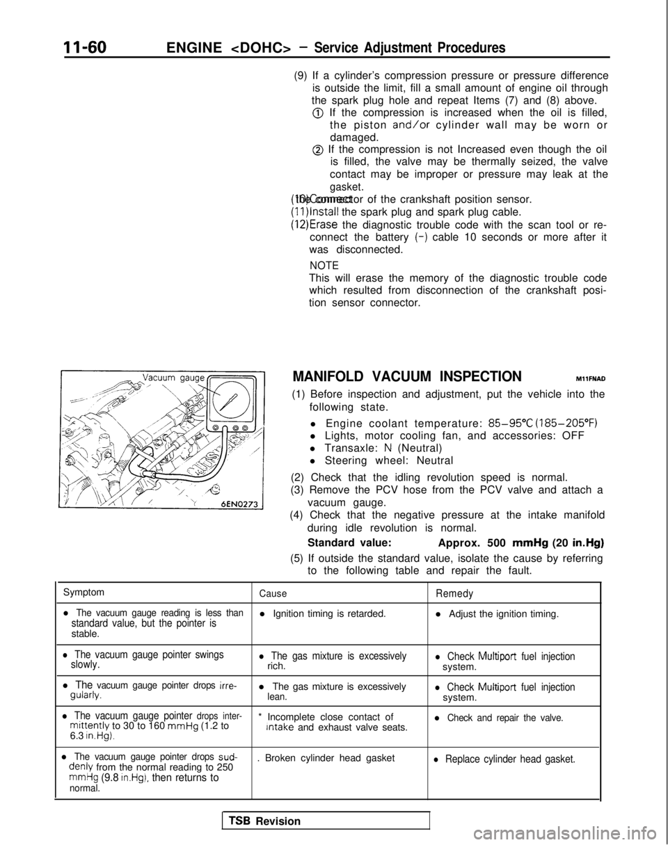
(3) Remove the PCV hose from the PCV valve and attach a
vacuum gauge.
(4) Check that the negative pressure at the intake manifold
during idle revolution is normal.
Standard value: Approx. 500 mmHg
(20 in.Hg)
(5) If outside the standard value, isolate the cause by referring to the following table and repair the fault.
Symptom
CauseRemedy
l The vacuum gauge reading is less thanstandard value, but the pointer isl Ignition timing is retarded. l Adjust the ignition timing.
stable.
l The vacuum gauge pointer swings
slowly.l The gas mixture is excessivelyrich.l Check Multiport fuel injectionsystem.
l The vacuum gauge pointer drops irre- gularly.
l The gas mixture is excessively
lean.l Check Multiport
fuel injectionsystem.
l The vacuum gauge pointer drops inter-mittently to 30 to 160 mmHg
(1.2 to * Incomplete close contact of Intake
and exhaust valve seats.l Check and repair the valve.
6.3 in.Hg).
l The vacuum gauge pointer drops sud- denly
from the normal reading to 250 . Broken cylinder head gasketl Replace cylinder head gasket.
mmHg (9.8 in.Hg), then returns tonormal.
TSB Revision
Page 141 of 1273
ENGINE
J
Tensioner armTensioner arm
TSB Revision
. ADJUSTMENT OF TIMING BELT TENSION
(1) After turning the crankshaft
l/4 turn counterclockwise,
turn it clockwise to move the No. 1 cylinder to top dead
center.
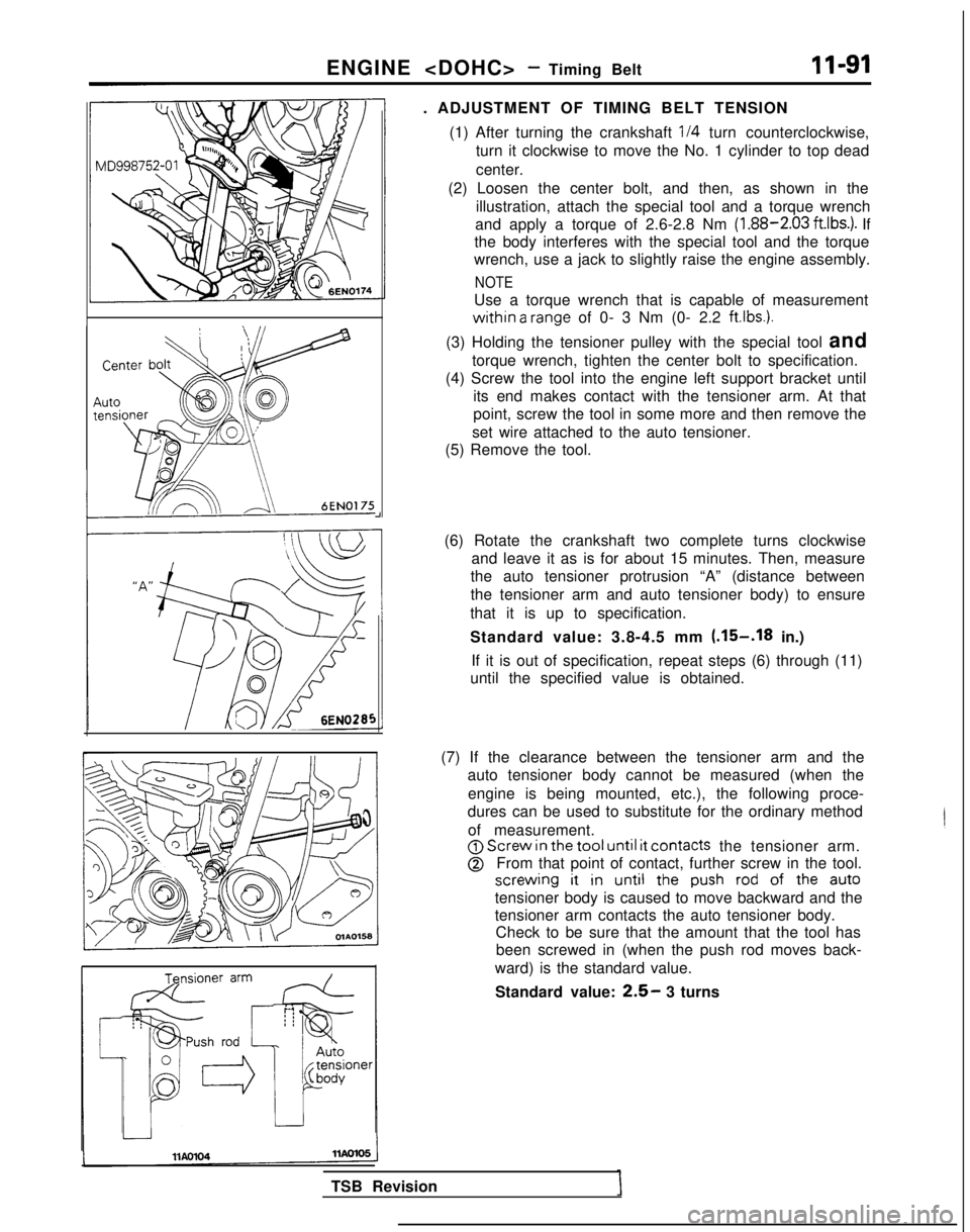
(2) Loosen the center bolt, and then, as shown in the illustration, attach the special tool and a torque wrench
and apply a torque of 2.6-2.8 Nm (1.88-2.03
ft.lbs.). If
the body interferes with the special tool and the torque
wrench, use a jack to slightly raise the engine assembly.
NOTE
Use a torque wrench that is capable of measurement
within a range of 0- 3 Nm (0- 2.2 ftlbs.).
(3) Holding the tensioner pulley with the special tool and torque wrench, tighten the center bolt to specification.
(4) Screw the tool into the engine left support bracket until its end makes contact with the tensioner arm. At that
point, screw the tool in some more and then remove the
set wire attached to the auto tensioner.
(5) Remove the tool.
(6) Rotate the crankshaft two complete turns clockwise and leave it as is for about 15 minutes. Then, measure
the auto tensioner protrusion “A” (distance between
the tensioner arm and auto tensioner body) to ensure
that it is up to specification.
Standard value: 3.8-4.5 mm
(.15-.I8 in.)
If it is out of specification, repeat steps (6) through (11)
until the specified value is obtained.
(7) If the clearance between the tensioner arm and the auto tensioner body cannot be measured (when the
engine is being mounted, etc.), the following proce-
dures can be used to substitute for the ordinary method
of measurement.
@j Screw in
the tool until it
contacts the tensioner arm.
@From that point of contact, further screw in the tool.
screwing it in
until the push
rod
of the auto
tensioner body is caused to move backward and the
tensioner arm contacts the auto tensioner body.
Check to be sure that the amount that the tool has
been screwed in (when the push rod moves back-
ward) is the standard value.
Standard value:
2.5- 3 turns
Page 145 of 1273
FUEL SYSTEM
FUEL SYSTEM
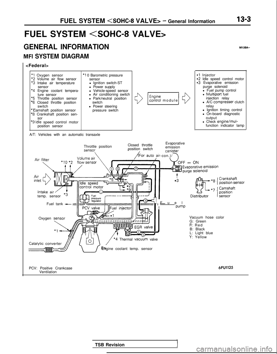
GENERAL INFORMATION
MFI SYSTEM DIAGRAM
*1 Oxygen sensor
*2
Volume air flow sensor *3
Intake air temperature
sensor *4
Engine coolant tempera-
ture sensor *5
Throttle position sensor *6
Closed throttle position
switch *7 Camshaft position sensor
*8
Crankshaft position sen-
sor
‘9 Idle
speed control motor
position sensor
*I 0 Barometric pressure sensor
l Ignition switch-ST
l Power supply
l Vehicle-speed sensor
l Air conditioning switch
l Park/neutral position
switch
l Power steering pressure switch
A/T: Vehicles with an automatic transaxle
()/ $%?i modul
e
Closed throttle Evaporative
position switch emission canister
ir-con.)/ \
10
Throttle position
temp. sensor Fuel tank
- =
Oxygen M13BA-
I
*I Injector~2 Idle speed control motort3 Evaporative emission
purge solenoid
l Fuel pump control
l Multiport fuelinjection relay
l A/C compresser clutch
relay
l Ignition timing control
l On-board diagnostic
output
l Check engine/mul-function indicator lamp
Fue
l
: -
I
pump
purge
solenolo Catalvtic
converter
\/ *4 Thermal vacu
G: Green
R: Re
d
B: Black
L: Light blue
Y: Yellow
dJJ/ U’Engine coolant temp. sensor
PCV: Positive Crankcase Ventilation
6FU1125
TSB Revision
Page 146 of 1273
13-4FUEL SYSTEM
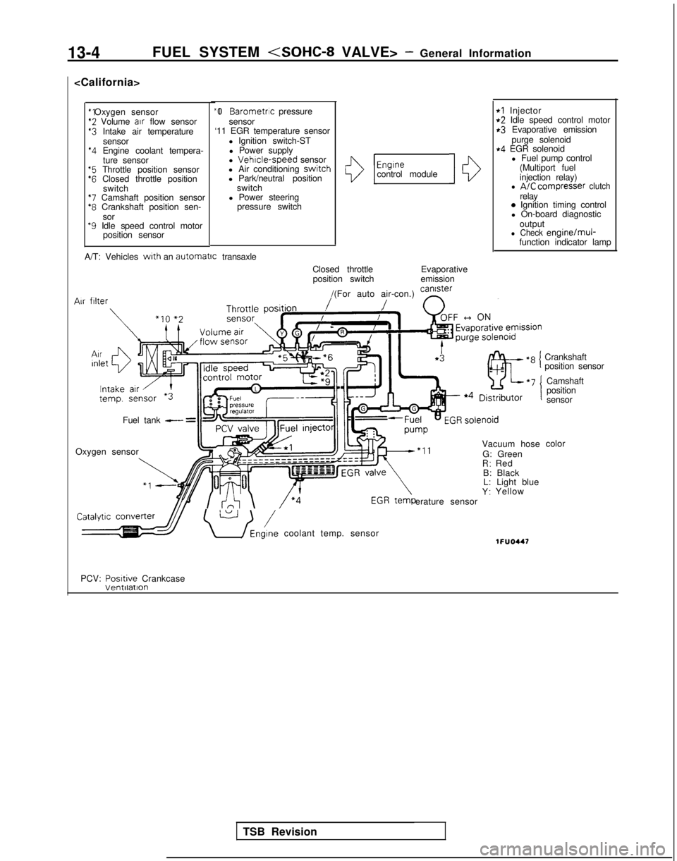
*2 Volume
air
flow sensor$3 Intake air temperature
sensor
*4 Engine coolant tempera-ture sensor
“5 Throttle position sensor‘6 Closed throttle position switch
*7 Camshaft position sensor*8 Crankshaft position sen-
sor
*9 Idle speed control motor position sensor “I 0
Barometric pressure
sensor
‘11 EGR temperature sensor
l Ignition switch-STl Power supply
l
Vehrcle-speed sensor
l Air conditioning switch
l Park/neutral position
switch
l Power steering pressure switchI13
Engrnecontrol module10
rl Injectort2 Idle speed control motorr3 Evaporative emission
purge solenoid
r4 EGR solenoidl Fuel pump control
(Multiport fuel
injection relay)
l A/C compresser clutchrelay0 Ignition timing control
l On-board diagnostic
output
l Check engine/muj-function indicator lamp
A/T: Vehicles
with an automatrc
transaxle
Closed throttleposition switch Evaporative
emission
/(For auto air-con.) can’ster
/ n
Vacuum hose
G: Green
R: Red
B: Black L: Light blue
Y: Yellow
erature sensor Air
filter
Fuel tank - =
Oxygen sensor
\ U /Eni coolant temp. sensor1FUO447
Crankshaft
position sensor
Camshaft
position
sensor
color
PCV: Posrtive
Crankcase
TSB Revision
Page 152 of 1273
13-10
FUEL SYSTEM
at sensor side
1\~“‘,““W,O,’ ‘\*N 4-cnDQ5a,, \llllf,,
c 3 c-11 ‘.<-!
( .[&
;%* \ g ~ &.$$~&%,;
0%: E
.Oj-,,
giI lOWI -,n
/ ~ ( ~~‘-~~~
-.mo .u. m,.0 - rj*> ;;
indicator lamp68AOO93
l
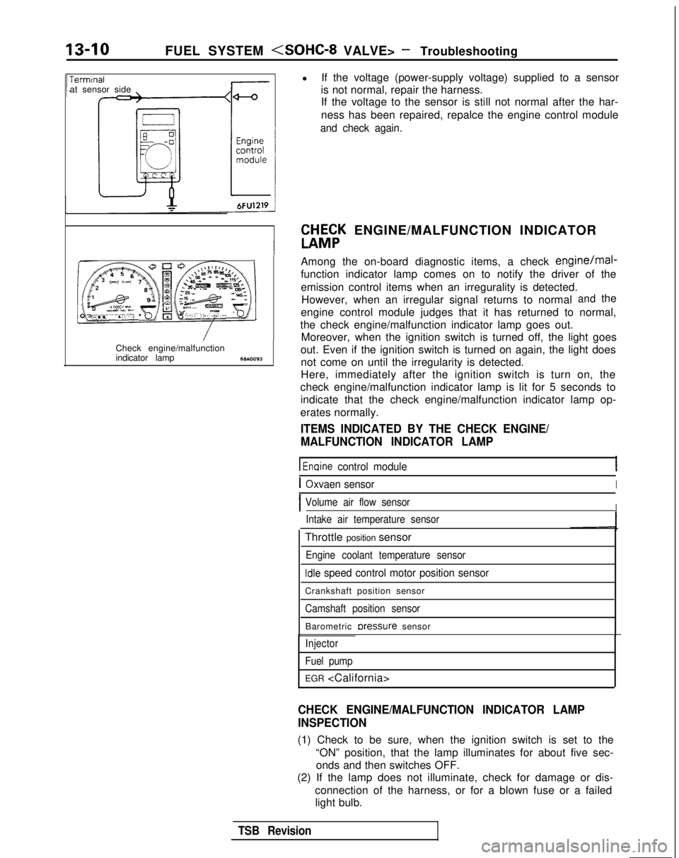
If the voltage (power-supply voltage) supplied to a sensor
is not normal, repair the harness. If the voltage to the sensor is still not normal after the har-
ness has been repaired, repalce the engine control module
and check again.
W&K ENGINE/MALFUNCTION INDICATOR
Among the on-board diagnostic items, a check
engine/mal-
function indicator lamp comes on to notify the driver of the
emission control items when an irregurality is detected. However, when an irregular signal returns to normal
andthe
engine control module judges that it has returned to normal,
the check engine/malfunction indicator lamp goes out. Moreover, when the ignition switch is turned off, the light goes
out. Even if the ignition switch is turned on again, the light does not come on until the irregularity is detected.
Here, immediately after the ignition switch is turn on, the
check engine/malfunction indicator lamp is lit for 5 seconds to indicate that the check engine/malfunction indicator lamp op-
erates normally.
ITEMS INDICATED BY THE CHECK ENGINE/
MALFUNCTION INDICATOR LAMP
1 Enaine control module
IOxvaen sensorI
IVolume air flow sensorIIntake air temperature sensor
Throttle position sensor
Engine coolant temperature sensor
Idle speed control motor position sensor
Crankshaft position sensor
Camshaft position sensor
Barometric rxessure sensor
Injector
Fuel pump
EGR
CHECK ENGINE/MALFUNCTION INDICATOR LAMP
INSPECTION
(1) Check to be sure, when the ignition switch is set to the “ON” position, that the lamp illuminates for about five sec-onds and then switches OFF.
(2) If the lamp does not illuminate, check for damage or dis-
connection of the harness, or for a blown fuse or a failedlight bulb.
TSB Revision
Page 155 of 1273
FUEL SYSTEM
No.
43
4
-
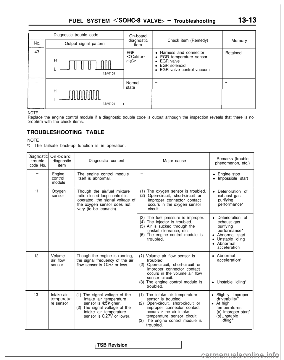
Diagnostic trouble code
Output signal pattern On-board
diagnostic item Check item (Remedy)
Memory
EGRl Harness and connector
Retained
l EGR solenoid
L u u u I nnnl EGR valve control vacuum12A0105
Normal -state
-
H
L12A0104I 1
NOTEReplace the engine control module if a diagnostic trouble code is output\
although the inspection reveals that there is no
oroblem
with the check items.
TROUBLESHOOTING TABLE NOTE
*:The failsafe back-up function is in operation.
Diagnostic On-board
trouble diagnostic Diagnostic content
code No.item Major cause
Remarks (trouble
phenomenon, etc.)
-EngineThe engine control module-l Engine stop
control itself is abnormal. l Impossible start
module
11Oxygen Though the air/fuel mixture (1) The oxygen sensor is troubled.
l Deterioration of
sensor ratio closed loop control is (2) Open-circuit, short-circuit or
exhaust gas
operated, the signal voltage of improper connector contactpurifying
the oxygen sensor does not occurs in the oxygen sensorperformance*
vary (to be lean/rich). circuit.
(3) The fuel pressure is improper. l Deterioration of
(4) The injector is troubled. exhaust gas
(5) Air is sucked through the purifying
gasket clearance, etc. performance*
(6) The engine control module is l Abnormal start
troubled. l Unstable idling
l Abnormal
acceleration
12Volume
air flow
sensor Though the engine is running,(I) Volume air flow sensor is
l Abnormal
the signal frequency of the air troubled.acceleration*
flow sensor is
1 OHz or less. (2) Open-circuit, short-circuit or
improper connector contact
occurs in the volume air flow
sensor circuit.
(3) The engine control module is l Unstable idling*
troubled.
13Intake air (1) The signal voltage of the (1) The intake air temperature
l Slightly impropertemperatu-intake air temperaturesensor is troubled.driveability*re sensorsensor is 4.5V or higher.
(2) Open-circuit, short-circuit or l At high
(2) The signal voltage of the improper connector contact
temperatures,
intake air temperature occurs in the air intake
(a) Improper start*
sensor is
0.27V or lower. temperature sensor circuit.
(3) The engine control module is(b) ;J;pe
troubled.
1 TSB Revision
Page 156 of 1273
13-14
FUEL SYSTEM
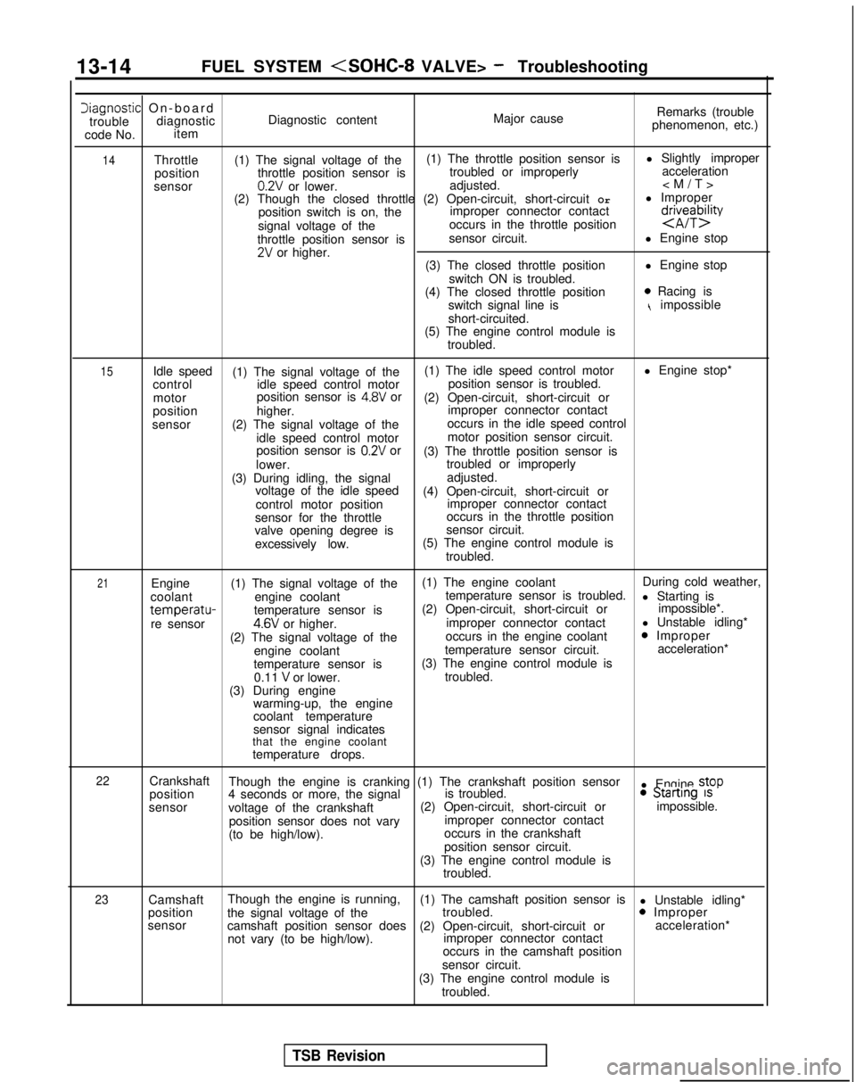
Iiagnostic On-boar
d
trouble diagnostic Diagnostic content Major causeRemarks (trouble
phenomenon, etc.)
code No. item
14Throttle
(1) The signal voltage of the (1) The throttle position sensor is
l Slightly improper
position throttle position sensor is troubled or improperly
acceleration
sensor
0.2V or lower. adjusted.
(2) Though the closed throttle (2) Open-circuit, short-circuit Orl Improper
position switch is on, the improper connector contact
signal voltage of the occurs in the throttle position
d$eybzty
throttle position sensor is
sensor circuit.
l Engine stop2V or higher.
(3) The closed throttle position l Engine stop
switch ON is troubled.
(4) The closed throttle position
0 Racing is
switch signal line ist impossible
short-circuited.
(5) The engine control module is
troubled.
15Idle speed (1) The signal voltage of the (1) The idle speed control motor
l Engine stop*
control idle speed control motor position sensor is troubled.
motor position sensor is
4.8V or
(2) Open-circuit, short-circuit or
position higher. improper connector contact
sensor (2) The signal voltage of the occurs in the idle speed control
idle speed control motor motor position sensor circuit.
position sensor is
0.2V or (3) The throttle position sensor is
lower. troubled or improperly
(3) During idling, the signal adjusted.
voltage of the idle speed (4) Open-circuit, short-circuit or
control motor position improper connector contact
sensor for the throttle occurs in the throttle position
valve opening degree is sensor circuit.
excessively low. (5) The engine control module is
troubled.
21Engine (1) The signal voltage of the (1) The engine coolant
During cold weather,
coolant engine coolant temperature sensor is troubled.
l Starting is
temperatu-temperature sensor is(2) Open-circuit, short-circuit or
impossible*.
re sensor4.6V or higher. improper connector contact
l Unstable idling*
(2) The signal voltage of the occurs in the engine coolant0 Improper
engine coolant temperature sensor circuit. acceleration*
temperature sensor is (3) The engine control module is
0.11
V or lower. troubled.
(3) During engine warming-up, the engine
coolant temperature
sensor signal indicates
that the engine coolant
temperature drops.
22Crankshaft Though the engine is cranking (1) The crankshaft position sensor
l Engine stop
position 4 seconds or more, the signal is troubled.0 Startrng 1s
sensor
voltage of the crankshaft (2) Open-circuit, short-circuit or
impossible.
position sensor does not vary improper connector contact
(to be high/low). occurs in the crankshaft
position sensor circuit.
(3) The engine control module is troubled.
23Camshaft Though the engine is running,
(1) The camshaft position sensor is
l Unstable idling*
position the signal voltage of the troubled.0 Improper
sensor camshaft position sensor does (2) Open-circuit, short-circuit or acceleration*
not vary (to be high/low). improper connector contact
occurs in the camshaft position
sensor circuit.
(3) The engine control module is troubled.
TSB Revision
Page 158 of 1273
13-16
FUEL SYSTEM
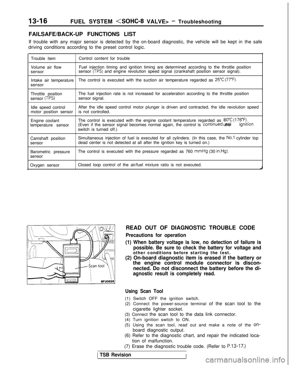
FAILSAFE/BACK-UP FUNCTIONS LIST
If trouble with any major sensor is detected by the on-board diagnostic,\
the vehicle will be kept in the safe
driving conditions according to the preset control logic.
Trouble item Control content for trouble
Volume air flow Fuel injection timing and ignition timing are determined according to th\
e throttle position
sensor sensor
(TPS) and engine revolution speed signal (crankshaft position sensor signal)\
.
Intake air temperature The control is executed with the suction air temperature regarded as
25°C (77°F).
sensor
Throttle position The fuel injection rate is not increased for acceleration according to t\
he throttle position
sensor
(TPS)sensor signal.
Idle speed control After the idle speed control motor plunger is driven and contracted, the\
idle revolution speed
motor position sensor is not controlled.
Engine coolant The control is executed with the engine coolant temperature regarded as \
8OO.C (176°F).temperature sensor (Even if the sensor signal becomes normal again, the control is continued
until the ignltlon
switch is turned off.)
Camshaft position Simultaneous injection of fuel is executed for all cylinders. (In this \
case, the
No.1 cylinder top
sensor dead center is not detected at all after the ignition key is turned on.)\
Barometric pressure The control is executed with the pressure regarded as 760 mmHg
(30
in.Hg).
sensor
Oxygen sensor Closed loop control of the air/fuel mixture ratio is not executed.
i
READ OUT OF DIAGNOSTIC TROUBLE CODE
Precautions for operation
(1) When battery voltage is low, no detection of failure is possible. Be sure to check the battery for voltage and
other conditions before starting the test.
(2) On-board diagnostic item is erased if the battery or the engine control module connector is discon-
nected. Do not disconnect the battery before the di-
agnostic result is completely read.
Using Scan Tool
(1) Switch OFF the ignition switch.
(2) Connect the power-source terminal of the scan tool to the
cigarette lighter socket.
(3) Connect the scan tool to the data link connector. (4) Turn ignition switch to ON.
(5) Using the scan tool, read out and make a note of the
on-
board diagnostic output.
(6) Refer to the diagnostic chart, and repair the indicated loca-
tion of malfunction.
(7) Erase the diagnostic trouble code. (Refer to
P.13-17.)
1 TSB RevisionI