1989 MITSUBISHI GALANT jack points
[x] Cancel search: jack pointsPage 77 of 1273
ENGINE
\
r
MatingC
-I
1
J-1.‘T
:-c’ 000510020
SERVICE POINTS OF REMOVALMllJBAl
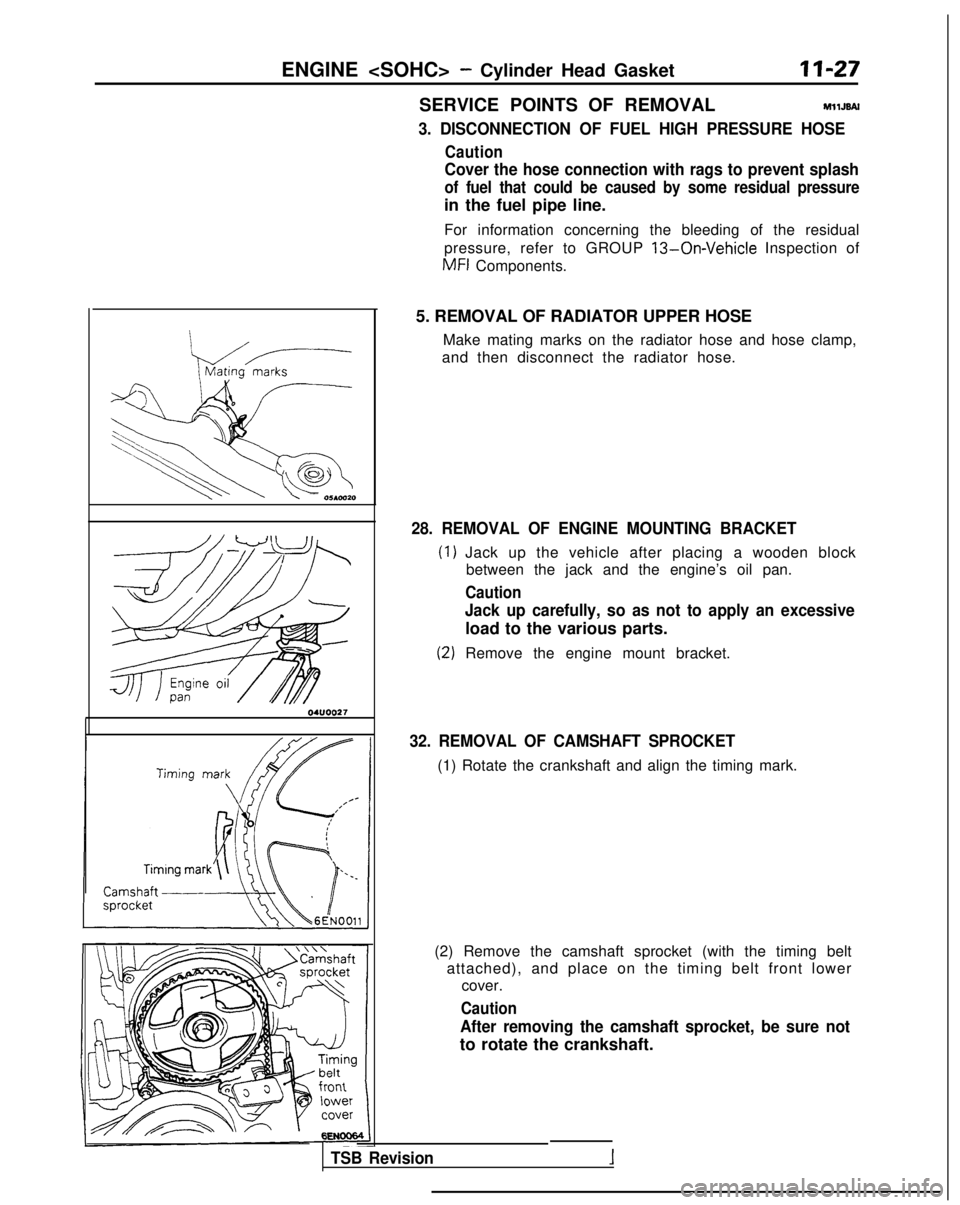
3. DISCONNECTION OF FUEL HIGH PRESSURE HOSE
Caution
Cover the hose connection with rags to prevent splash
of fuel that could be caused by some residual pressure
in the fuel pipe line.
For information concerning the bleeding of the residual
pressure, refer to GROUP
13-On-Vehicle Inspection of
MFI
Components.
5. REMOVAL OF RADIATOR UPPER HOSE Make mating marks on the radiator hose and hose clamp,
and then disconnect the radiator hose.
28. REMOVAL OF ENGINE MOUNTING BRACKET
Jack up the vehicle after placing a wooden block between the jack and the engine’s oil pan.
Caution
Jack up carefully, so as not to apply an excessive
load to the various parts.
Remove the engine mount bracket.
32. REMOVAL OF CAMSHAFT SPROCKET
(1) Rotate the crankshaft and align the timing mark.
(2) Remove the camshaft sprocket (with the timing belt attached), and place on the timing belt front lower cover.
Caution
After removing the camshaft sprocket, be sure not
to rotate the crankshaft.
TSB Revision
Page 86 of 1273
11-36
ENGINE
Timing mark
\
Camshaft sprocket
;/
i
\
IlEN0017
Tit
e
I;
OlAO550
01A0551
SERVICE POINTS OF REMOVALMllKBDF
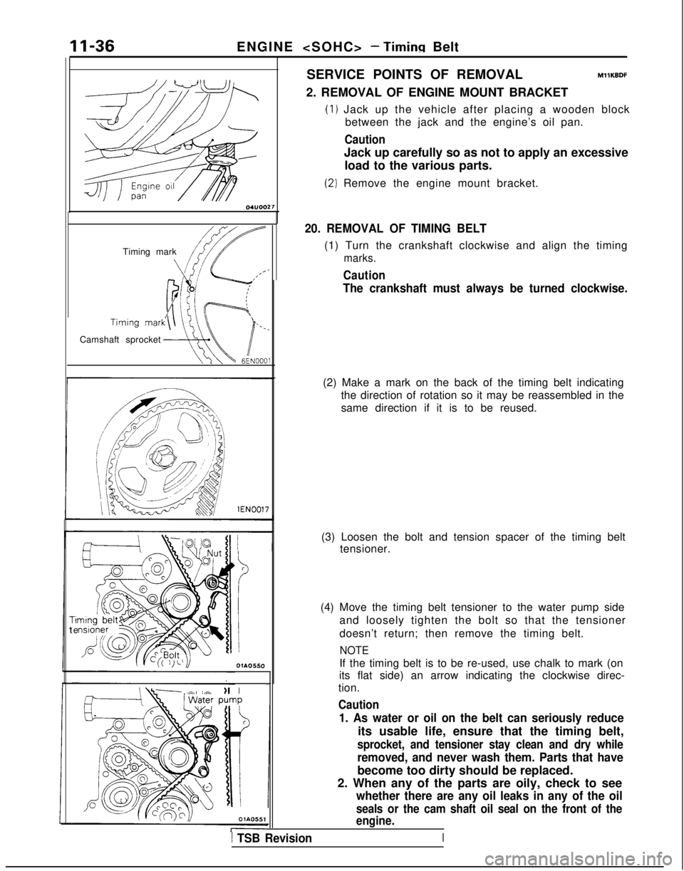
2. REMOVAL OF ENGINE MOUNT BRACKET
(1) Jack up the vehicle after placing a wooden block
between the jack and the engine’s oil pan.
Caution
Jack up carefully so as not to apply an excessive
load to the various parts.
(2) Remove the engine mount bracket.
20. REMOVAL OF TIMING BELT
(1) Turn the crankshaft clockwise and align the timing
marks.
Caution
The crankshaft must always be turned clockwise.
(2) Make a mark on the back of the timing belt indicating the direction of rotation so it may be reassembled in the
same direction if it is to be reused.
(3) Loosen the bolt and tension spacer of the timing belt tensioner.
(4) Move the timing belt tensioner to the water pump side and loosely tighten the bolt so that the tensioner
doesn’t return; then remove the timing belt.
NOTE
If the timing belt is to be re-used, use chalk to mark (on
its flat side) an arrow indicating the clockwise direc-
tion.
Caution
1. As water or oil on the belt can seriously reduce
its usable life, ensure that the timing belt,
sprocket, and tensioner stay clean and dry while
removed, and never wash them. Parts that have
become too dirty should be replaced.
2. When any of the parts are oily, check to see
whether there are any oil leaks in any of the oil
seals or the cam shaft oil seal on the front of the
engine.
1 TSB Revision
Page 94 of 1273
ENGINE
A Timing
mark
Timingmark
mark
-/Crank&aft swocketOlA0667 lEN0017SERVICE POINTS OF REMOVAL
MllKBDG
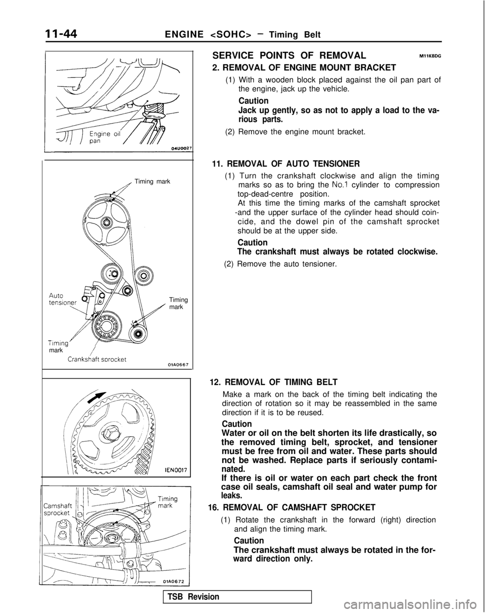
2. REMOVAL OF ENGINE MOUNT BRACKET
(1) With a wooden block placed against the oil pan part ofthe engine, jack up the vehicle.
Caution
Jack up gently, so as not to apply a load to the va-
rious parts.
(2) Remove the engine mount bracket.
11. REMOVAL OF AUTO TENSIONER
(1) Turn the crankshaft clockwise and align the timing marks so as to bring the
No.1 cylinder to compression
top-dead-centre position. At this time the timing marks of the camshaft sprocket
-and the upper surface of the cylinder head should coin- cide, and the dowel pin of the camshaft sprocket
should be at the upper side.
Caution
The crankshaft must always be rotated clockwise.
(2) Remove the auto tensioner.
12. REMOVAL OF TIMING BELT
Make a mark on the back of the timing belt indicating the
direction of rotation so it may be reassembled in the same
direction if it is to be reused.
Caution
Water or oil on the belt shorten its life drastically, so
the removed timing belt, sprocket, and tensioner must be free from oil and water. These parts should
not be washed. Replace parts if seriously contami-
nated.
If there is oil or water on each part check the front
case oil seals, camshaft oil seal and water pump for
leaks.
16. REMOVAL OF CAMSHAFT SPROCKET
(1) Rotate the crankshaft in the forward (right) direction
and align the timing mark.
Caution
The crankshaft must always be rotated in the for-
ward direction only.
TSB Revision
Page 132 of 1273
II-82
SEALING POINTSENGINE
- Timing Belt
olaoo4~
0 1 A0583
Sealant: 3M ATD Part No.8660
or equivalent 04UOO27
1
Intake cam-IDowel
pinshaft sprocket
/~~*;~i~g~\Timing 1
- .,ICrankshatt-Oil pum
p
,
_sprockekI sproKer
OlAOOSl
1
SERVICE POINTS OF REMOVALMl 1KBDG
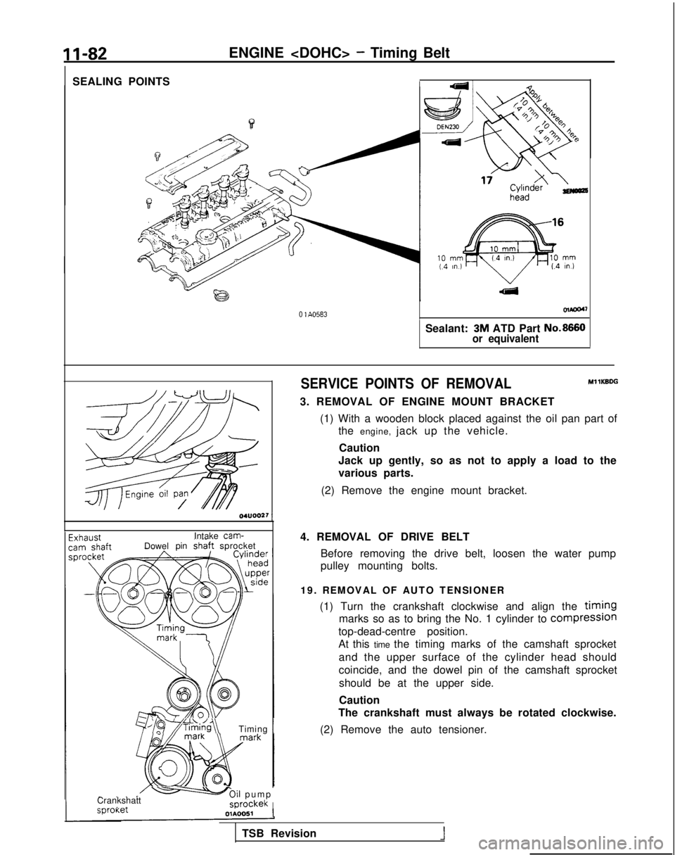
3. REMOVAL OF ENGINE MOUNT BRACKET
(1) With a wooden block placed against the oil pan part ofthe engine, jack up the vehicle.
Caution
Jack up gently, so as not to apply a load to the
various parts.
(2) Remove the engine mount bracket.
4. REMOVAL OF DRIVE BELT Before removing the drive belt, loosen the water pump
pulley mounting bolts.
19. REMOVAL OF AUTO TENSIONER (1) Turn the crankshaft clockwise and align the
timing
marks so as to bring the No. 1 cylinder to compresslon
top-dead-centre position.
At this time the timing marks of the camshaft sprocket
and the upper surface of the cylinder head should
coincide, and the dowel pin of the camshaft sprocketshould be at the upper side.
Caution
The crankshaft must always be rotated clockwise.
(2) Remove the auto tensioner.
TSB Revision
1
Page 570 of 1273
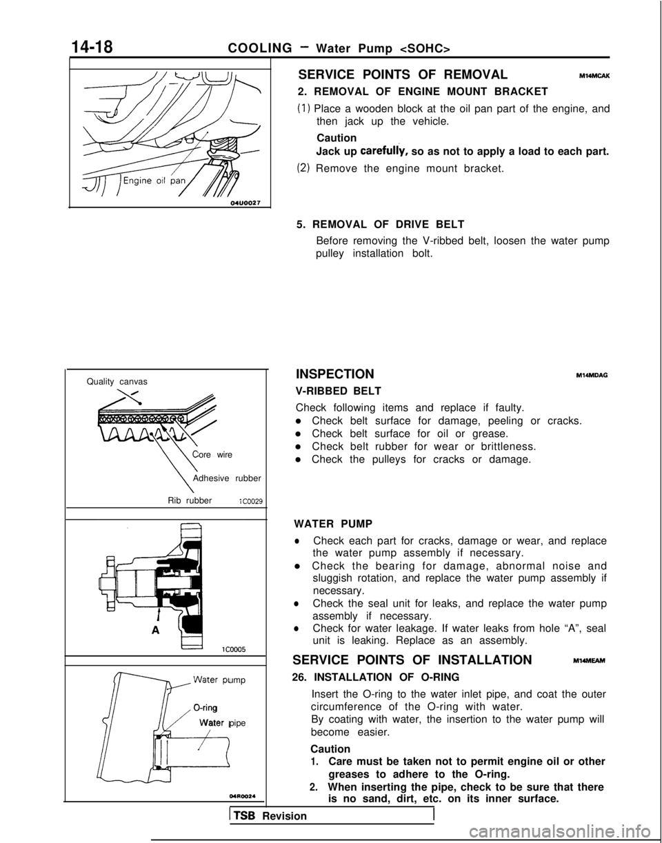
14-18COOLING - Water Pump
Quality canvas Core wire
\\Adhesive rubber
\Rib rubberlCOO29
W
ater pump
J--iLi+
O-ring
W
ater pipe
I I
SERVICE POINTS OF REMOVALMl4MCAK
2. REMOVAL OF ENGINE MOUNT BRACKET
(1) Place a wooden block at the oil pan part of the engine, and
then jack up the vehicle.
Caution
Jack up carefully,
so as not to apply a load to each part.
(2) Remove the engine mount bracket.
5. REMOVAL OF DRIVE BELT Before removing the V-ribbed belt, loosen the water pump
pulley installation bolt.
INSPECTION
V-RIBBED BELT
M14MDAG
Check following items and replace if faulty.
l Check belt surface for damage, peeling or cracks.
l Check belt surface for oil or grease.
l Check belt rubber for wear or brittleness.
l Check the pulleys for cracks or damage.
WATER PUMP
lCheck each part for cracks, damage or wear, and replace
the water pump assembly if necessary.
l Check the bearing for damage, abnormal noise and sluggish rotation, and replace the water pump assembly if
necessary.
lCheck the seal unit for leaks, and replace the water pump
assembly if necessary.
lCheck for water leakage. If water leaks from hole “A”, seal
unit is leaking. Replace as an assembly.
SERVICE POINTS OF INSTALLATION
Ml4MEAm
26. INSTALLATION OF O-RING Insert the O-ring to the water inlet pipe, and coat the outer
circumference of the O-ring with water. By coating with water, the insertion to the water pump will
become easier.
Caution
1.Care must be taken not to permit engine oil or other
greases to adhere to the O-ring.
2.When inserting the pipe, check to be sure that there is no sand, dirt, etc. on its inner surface.
1 TSB Revision
Page 677 of 1273
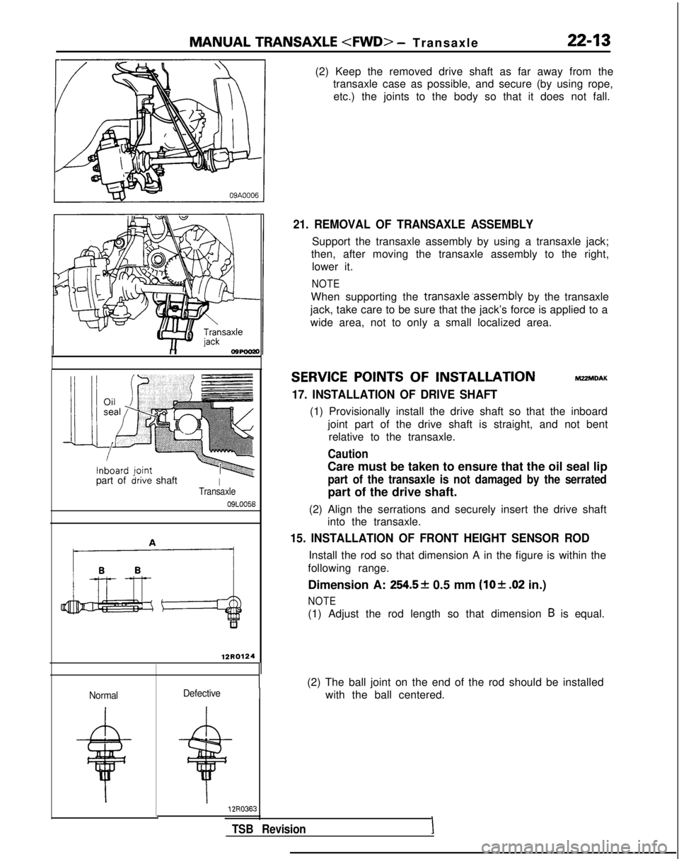
MANUAL TRANSAXLE
- Transaxl
e
22-13
part ofirive shaftITransaxle
09LOO58
12R0124
Normal
12R036:s
TSB Revision
(2) Keep the removed drive shaft as far away from the
transaxle case as possible, and secure (by using rope,
etc.) the joints to the body so that it does not fall.
21. REMOVAL OF TRANSAXLE ASSEMBLY
Support the transaxle assembly by using a transaxle jack;
then, after moving the transaxle assembly to the right, lower it.
NOTE
When supporting the transaxle’assembly by the transaxle
jack, take care to be sure that the jack’s force is applied to a
wide area, not to only a small localized area.
SERVICE POINTS OF INSTALLATION MZ?MDAK
17. INSTALLATION OF DRIVE SHAFT
(1) Provisionally install the drive shaft so that the inboard
joint part of the drive shaft is straight, and not bentrelative to the transaxle.
Caution
Care must be taken to ensure that the oil seal lip
part of the transaxle is not damaged by the serrated
part of the drive shaft.
(2) Align the serrations and securely insert the drive shaft into the transaxle.
15. INSTALLATION OF FRONT HEIGHT SENSOR ROD
Install the rod so that dimension A in the figure is within the
following range.
Dimension A:
254.5* 0.5 mm (lo& .02 in.)
NOTE
(1) Adjust the rod length so that dimension B is equal.
(2) The ball joint on the end of the rod should be installed with the ball centered.
Defective
I
Page 927 of 1273
33A-6FRONT SUSPENSION - Strut Assembly
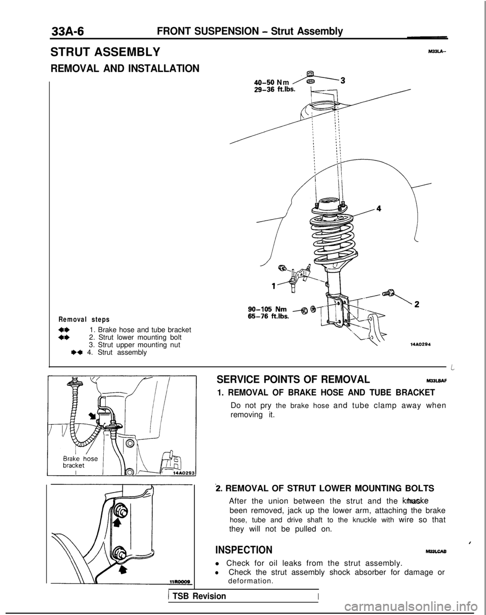
STRUT ASSEMBLY
REMOVAL AND INSTALLATION-
Removal steps
::1. Brake hose and tube bracket
2. Strut lower mounting bolt
3. Strut upper mounting nut
WI 4. Strut assembly
40-50 Nm -3
14AO294
SERVICE POINTS OF REMOVALM32UAF
1. REMOVAL OF BRAKE HOSE AND TUBE BRACKET
Do not pry the brake hose and tube clamp away when
removing it.
i. REMOVAL OF STRUT LOWER MOUNTING BOLTS
After the union between the strut and the knucke has
been removed, jack up the lower arm, attaching the brake hose, tube and drive shaft to the knuckle with wire so that
they will not be pulled on.
I
INSPECTIONMasLcAB
l Check for oil leaks from the strut assembly.
lCheck the strut assembly shock absorber for damage or
deformation.
1 TSB RevisionI
Page 1037 of 1273
33B-98ACTIVE-ELECTRONIC CONTROL SUSPENSION - Strut Assembly i
SERVICE POINTS OF REMOVALM33lBAE
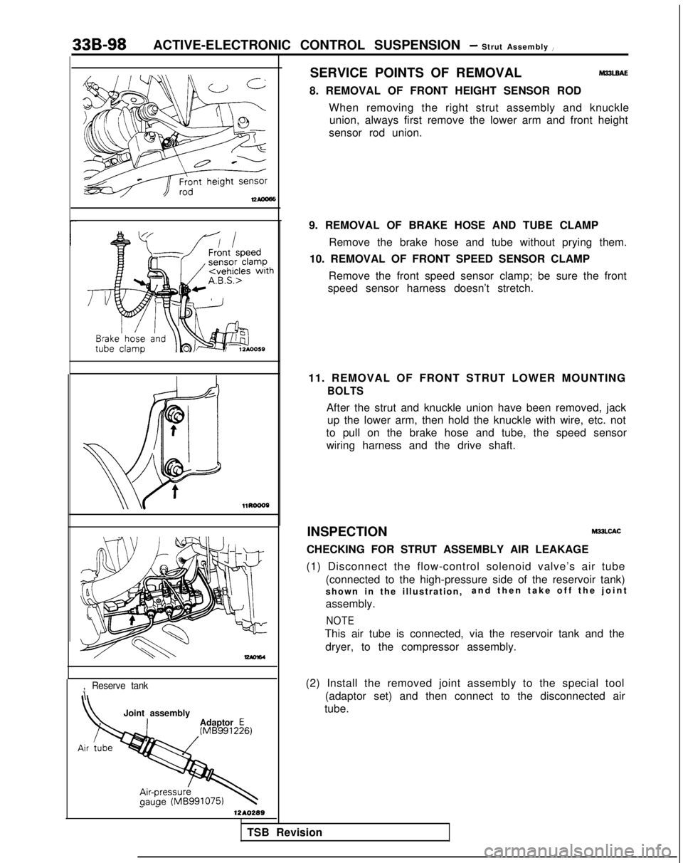
8. REMOVAL OF FRONT HEIGHT SENSOR RODWhen removing the right strut assembly and knuckleunion, always first remove the lower arm and front height
sensor rod union. l1RoooP
-
,Reserve tank
Joint assembly
Adaptor E
1 -1210289
9. REMOVAL OF BRAKE HOSE AND TUBE CLAMP
Remove the brake hose and tube without prying them.
10. REMOVAL OF FRONT SPEED SENSOR CLAMP
Remove the front speed sensor clamp; be sure the front
speed sensor harness doesn’t stretch.
11. REMOVAL OF FRONT STRUT LOWER MOUNTING
BOLTS
After the strut and knuckle union have been removed, jack up the lower arm, then hold the knuckle with wire, etc. not
to pull on the brake hose and tube, the speed sensor wiring harness and the drive shaft.
INSPECTION
M33LCAC
CHECKING FOR STRUT ASSEMBLY AIR LEAKAGE
(1) Disconnect the flow-control solenoid valve’s air tube (connected to the high-pressure side of the reservoir tank)
shown in the illustration, and then take off the join
t
assembly.
NOTE
This air tube is connected, via the reservoir tank and the dryer, to the compressor assembly.
(2) Install the removed joint assembly to the special tool (adaptor set) and then connect to the disconnected air
tube.
TSB Revision