Page 660 of 1273
21-10CLUTCH - Clutch Control
CLUTCH CONTROLh121 JA-
REMOVAL AND INSTALLATION
rPre-removal Operationl Draining of the Clutch FluidI
piigsql Bleeding of the Clutch Line (Refer
lo-15 Nm
7-11 ft.lbs.,
13-17 Nm
9-12
ft.lbs.
9-12 ft.lbs.
\-\ 8-12 Nm 6.0-8.7
ft.lbs.
/ 13-17
Nm
9-12 ftlbs.
13-17 Nm
9-12
ft.lbs.
Removal steps
I. Cotter pin2.Washer3. Clevis
pin
l a 4. Clutch tube
l + 5. Clutch tube
a*6. Hose clips*I) wq 7. Clutch hose8.Bracket
9. Clutch master cylinder
10.Sealer
08A0035
TSB Revision
Page 1206 of 1273
SERVICE BRAKES - Brake Booster35-85
BRAKE BOOSTER
REMOVAL AND INSTALLATION
MJSJA--
Pre-removal Operation
12@Draining of Brake Fluid
-!3\
Cl989 models> 6-9 ft.lbs. A 1
Post-installation Operation6upplying Brake Fulid*Bleeding (Refer to P.35-57.)l Adjustment of Brake Pedal(Refer to P.35-53.)15-18
Nrh ‘7II-13 ftlbs. :From
1990 models>
15-18 Nm 7II-13 ft.lbs.
Removal steps
1. Brake fluid level sensor connector
2. Brake tube
3. Master cylinder, hose, reservoir assembly +*
l +4. Vacuum hose5. Check valve
+* l +6. Vacuum hose with check valve7. Fitting
8. Cotter pin
9. Washer 10.
Clevis pi
n
11. Sealer
c*
12. Proportioning valve installation bolt
13. Brake tube (front left) installation bolt
14. Brake booster
14A05360
.a
QI1 II ;‘,:
4%14u0050
14Y626
Sealant: 3M ATD Part No.8663or equivalent
TSB Revision
Page 1229 of 1273
35-108SERVICE BRAKES- Rear Drum Brake
REAR DRUM BRAKE
REMOVAL AND INSTALLATION
13-17 Nm
9-12 ftlbs.
50-60 N
m
36-43
ftlbs.
/
13 12 11 14A.0359
Removal steps
Adjustment of wheel bearing end play
(Refer to GROUP 27-Service AdjustmentProcedures.)
1. Hubcap
2. Cotter pin
3. Lock cap
++ 4. Wheel bearing nut 5. Tongued washer
6. Outer bearing inner race
7. Brake drum
I)+Adjustment of shoe outside diameter
8. Shoe-to-lever spring
9. Shoe-to-shoe spring
10. Auto adjuster assembly
1 I. Retainer spring
12. Shoe hold down cups
13. Shoe hold down springs
14. Shoe hold down pins
15. Shoe and lining assembly
16. Shoe and lever assembly
17. Retainer
18. Wahser Pre-removal Operation
l Draining of Brake Fluid
(Refer to GROUP 36-Service
Adjust-
19. Auto adjuster lever
20. Parking brake lever
21. Snap ring
22. Brake tube
23. Backing plate
TSB Revision
Page 1232 of 1273

SERVICE BRAKES - Rear Drum Brake/Rear Brake Wheel Cylinder35-I 11
(5) Then once again tighten the wheel bearing nut to 10
Nm (7
ft.lbs.).
(6) Install the lock cap and split pin.
(7) If the position of the cotter pin is not matched with the
holes of the lock cap, reposition the lock cap so that the
holes align. If this can not be accomplished, back off the
nut by not more than 15”.
Caution
Check to be sure that the lock nut cannot b
e
loosened manually.
(8) After setting the split pin in place, seat the bearing in the same manner as in step (2).
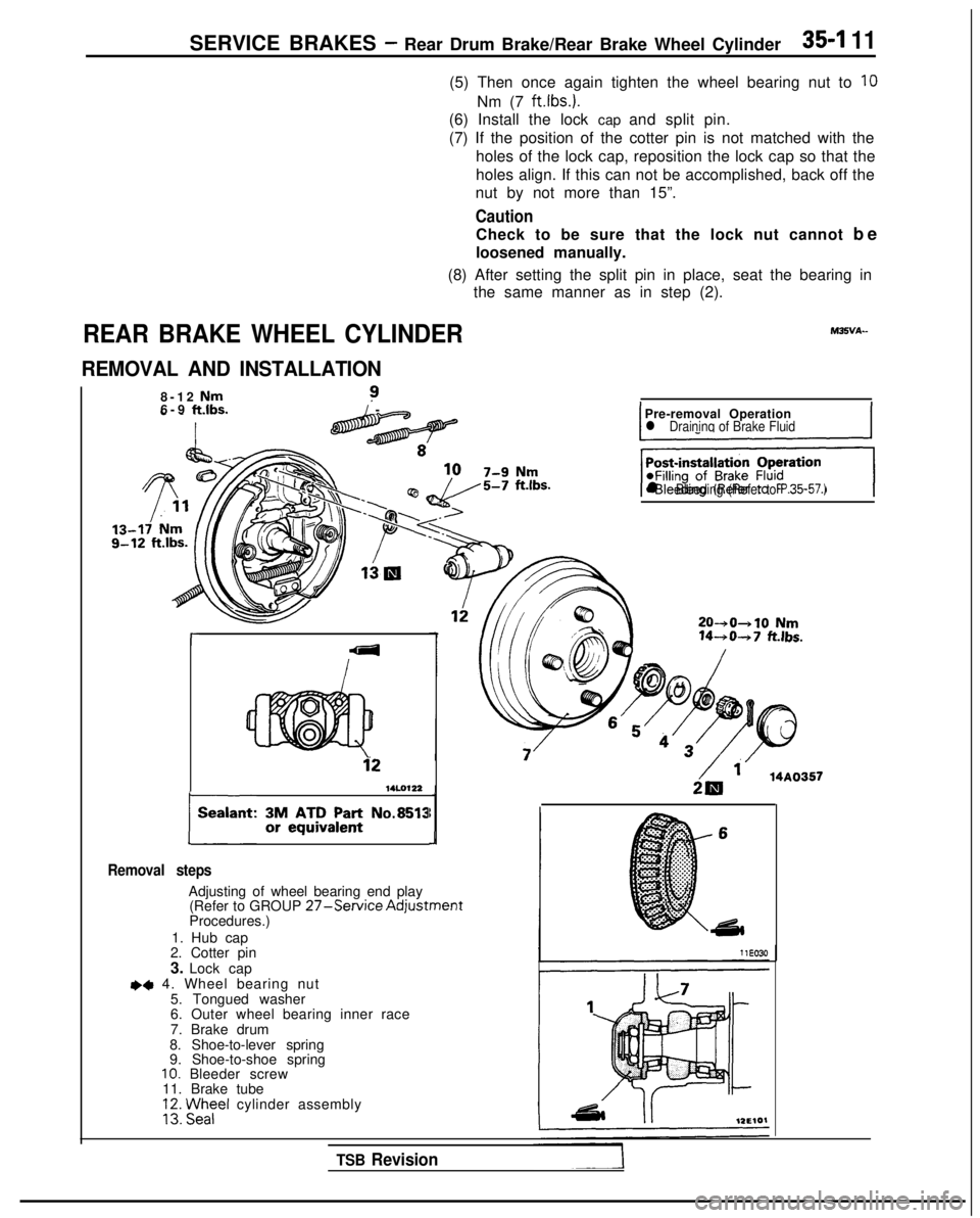
REAR BRAKE WHEEL CYLINDER
REMOVAL AND INSTALLATION
8-12 Nm?6-9 ft.lbs./
-
r
14LO122
plant: ~AA;;~~n’: No.8513
Removal steps
Adjusting of wheel bearing end play (Refer to GROUP 27-Service AdjustmentProcedures.)
1. Hub cap
2. Cotter pin
3. Lock cap
~~ 4. Wheel bearing nut
5. Tongued washer
6. Outer wheel bearing inner race
7. Brake drum
8. Shoe-to-lever spring
9. Shoe-to-shoe spring
10. Bleeder screw
11. Brake tube
VI Fezel cylinder assembly
IPre-removal Operationl Draininq of Brake FluidI
‘+iGJq
l Bleeding (Refer to P.35-57.)
20-+0+10 Nm 14-+0-+7
fklbs.
2& ‘. 14A0357
TSB Revision
Page 1235 of 1273
35-114SERVICE BRAKES - Rear Disc Brake
REAR DISC BRAKE
IEMOVAL AND INSTALLATIO
N
9-1
4 Nm
50-60Nm7-10
ft.lbs.
36-43 ft.lbs.
13-17 Nm9- 12 ft.lbs.
200-260
Nm144-199 ft.lbs.
Removal steps
1. Parking brake cable connection4,2. Brake hose connection
3. Rear brake assembly
4. Rear brake disc
5. Hub cap
l * 6. Wheel bearing nut
7. Washer
8. Rear speed sensor bracket
9. Rear hub assembly
14. Dust shield
I
Pre-removal Operation
*Draining of Brake Fluid
I
TSB RevisionI